I n t ro d u c t i o n — E l e c t ro n i c C i rc u i t P ro t e c t i o n E S X 1 0 - T
Electronic circuit protection type ESX10-T
is designed to ensure selective disconnection of 24VDC load systems.
24VDC power supplies, which are widely
used in industry today, will shut down
the output in the event of an overload
with the result that one faulty load in the
system can lead to complete disconnection of all loads.
Through selective disconnection the
ESX10-T responds much faster to overload or short circuit conditions than
the switch-mode power supply. This is
achieved by active current limitation.
The ESX10-T limits the highest possible
current to 1.3 to 1.8 times the selected
rated current of the circuit protector. Thus
it is possible to switch on capacitive loads
of up to 20,000 μF, but they are disconnected only in the event of an overload
or short circuit.
For optimal alignment with the characteristics of the application the current rating
of the ESX10-T can be selected in fixed
values from 0.5 A...12 A. Failure and
status indication are provided by a
multicolour LED and an integral shortcircuit-proof status output or a relay signal
contact. Remote operation is possible
by means of a remote reset signal or
a remote ON/OFF control signal.
The manual ON/OFF button allows
separate actuation and reset of
individual load circuits.
42
Upon detection of overload or short
circuit in the load circuit, the MOSFET
of the load output will be blocked to
interrupt the current flow. The load
circuit can be re-activated via the
remote electronic reset input, control
input or manually by means of the
ON/OFF button.
Features
• Selective load protection, electronic trip
characteristics
• Active current limitation for safe connection of capacitive loads up to 20,000 μF
and on overload/short circuit
• Clear status and failure indication
through LED, status output SF or
Si contact F
• Integral fail-safe element adjusted
to current rating
• Current ratings 0.5 A...12 A
• Width per unit only 12.5 mm
• Reliable overload disconnection with
1.1 x In plus, even with long load lines or
small cable cross sections (see table 3)
• Rail mounting
• Manual ON/OFF button (S1)
• Ease of wiring through busbar LINE+
and 0 V as well as signal bars and
bridges
• Control input IN+ for remote ON/OFF
signal (option)
• UL/CSA Hazardous area approved–
Class 1, Div 2
• Electronic reset input RE (option)
�E l e c t ro n i c C i rc u i t P ro t e c t i o n E S X 10 - T
Approvals
Technical data
Authority
UL2367 (E306740)
UL1604 (E322549)
(class 1, div. 2, group A, B, C, D)
UL508/ cUL 508
CSA file 165971:
CSA C22.2 No: 213 (class I, div. 2)
Groups A, B, C, D, T5
CSA C22.2 No: 142
Class 2
Meets requirements for Class 2 current limitation
(ESX10-T... 0.5 A / 1 A / 2 A / 3 A
Voltage rating
24VDC
24VDC
Current ratings
0.5...12 A
0.5...12 A
24VDC
0.5...12 A
24VDC
0.5...12 A
24VDC
0.5...12 A
(Tambient = 40°C, operating voltage Ub = 24VDC)
Status output SF
Electrical data
Status OUT
OFF condition
Technical data
(Tambient = 40°C, operating voltage Ub = 24VDC)
Operating data
Operating voltage Ub
Current rating In
Closed current I0
Status indication
by means of
Load circuit
Load output
Overload disconnection
Short-circuit current IK
Trip time
for electronic disconnection
Temperature disconnection
Low voltage monitoring
load output
24VDC (18...32 V)
fixed current ratings: 0.5, 1 A, 2 A, 3 A, 4 A,
6 A, 8 A, 10 A, 12 A
ON condition: typically 20...30 mA
depending on signal output
• multicolour LED:
GREEN: unit is ON, power-MOSFET
is switched on
- status output SF ON,
supplies + 24VDC
ORANGE: in the event of overload or
short circuit until electronic
disconnection
RED: - unit electronically disconnected
- load circuit/Power-MOSFET
OFF
OFF: - manually switched off
(S1 = OFF)
or device is dead
- undervoltage (Ub < 8 V)
- after switch-on till the end
of the delay period
• status output SF (option)
• potential-free signal contact F (option)
• ON/OFF/ condition of switch S1
Power-MOSFET switching output
(high side switch)
typically 1.1 x In (1.05...1.35 x In)
active current limitation (see table 1)
see time/current characteristics
typically 3 s at ILoad > 1.1 x In
typically 3 s...100 ms at ILoad > 1.8 x In
(or 1.5 x In/1.3 x In)
internal temperature monitoring with
electronic disconnection
with hysteresis, no reset required
load “OFF” at Ub < 8 V
Starting delay tstart
typically 0.5 sec after every switch-on
and after applying Ub
Disconnection of load circuit
electronic disconnection
Free-wheeling circuit
external free-wheeling diode
recommended with inductive load
Several load outputs must not be connected in parallel
Signal output F
Electrical data
ON condition LED green
OFF condition LED off
Fault condition LED orange
Fault condition LED red
ESX10-TB-101
ESX10-TB-102
Fault
Reset input RE
Electrical data
Reset signal RE
(terminal 22)
Control input IN+
Electrical data
Control signal IN+
(terminal 21)
Switch S1 ON/OFF
ESX10-TB-114/-124/
plus-switching signal output,
connects Ub to terminal 12 of module 17plus
nominal data: 24VDC / max. 0.2 A (short circuit proof)
status output is internally connected to
GND with a 10 kOhm resistor
ESX10-TB-114/-124 (signal status OUT),
at Ub = +24 V
+24 V = S1 is ON, load output connected through
0V = S1 is ON, load output blocked and/or
switch S1 is OFF
red LED lit
0 V level at status output when:
• switch S1 is in ON position, but device is
still in switch-on delay
• switch S1 is OFF, or control signal OFF,
device is switched off
• no operating voltage Ub
ESX10-TB-101/-102
potential-free signal contact
max. 30VDC/0.5 A, min. 10 V/10 mA
voltage Ub applied, switch S1 is in ON position
no overload, no short circuit
• device switched off (switch S1 is in OFF position)
• no voltage Ub applied
overload condition > 1.1 x In up to
electronic disconnection
electronic disconnection upon
overload or short circuit
device switched off with control signal
(switch S1 is in ON position)
single signal, make contact
contact SC/SO-SI open
single signal, break contact
contact SC/SO-SI closed
signal output fault conditions:
• no operating voltage Ub
• ON/OFF switch S1 is in OFF position
• red LED lighted
(electronic disconnection)
ESX10-TB-124
voltage: max. +32VDC
high > 8VDC ≤ 32VDC
low ≤ 3VDC > 0 V
power consumption typically 2.6 mA
(+24VDC)
min. pulse duration typically 10 ms
The electronically blocked ESX10-TB-124
may remotely be reset via an external
momentary switch due to the falling edge of
a +24 V pulse.
A common reset signal can be applied to
several devices simultaneously.
Switched on devices remain unaffected.
ESX10-TB-114
see reset input RE
+24V level (HIGH): device will be switched
on by a remote ON/OFF signal
0 V level (LOW): device will be switched
off by a remote ON/OFF signal
unit can only be switched on with S1 if a
HIGH level is applied to IN+
43
�E l e c t ro n i c C i rc u i t P ro t e c t i o n E S X 1 0 - T
Technical data
(Tambient = 40°C, operating voltage Ub = 24VDC)
General data
Fail-safe element:
Mounting
Ambient temperature
Storage temperature
Humidity
backup fuse for ESX10-T not required
because of the integral
redundant fail-safe element
LINE+ / LOAD+ / 0V
Terminals
screw terminals
max. cable cross section
flexible with wire end ferrule w/wo plastic sleeve
multi-lead connection
(2 identical cables)
rigid/flexible
flexible with wire end ferrule without plastic sleeve
flexible with TWIN wire end ferrule with plastic sleeve
wire stripping length
tightening torque (EN 60934)
Terminals
aux. contacts
screw terminals
max. cable cross section
flexible with wire end ferrule w/wo plastic sleeve
wire stripping length
tightening torque (EN 60934)
Housing material
moulded
M4
symmetrical rail to EN 50022-35x7.5
0...+50 °C (without condensation, see EN 60204-1)
-20...+70 °C
96 hrs/95 % RH/40 °C to IEC 60068-2-78-Cab
climate class 3K3 to EN 60721
3 g, test to IEC 68-2-6 test Fc
housing: IP20 DIN 40050
terminals: IP20 DIN 40050
emission: EN 61000-6-3
susceptibility: EN 61000-6-2
0.5 kV/2 pollution degree 2
re-inforced insulation in operating area
max. 32VDC (load circuit)
Vibration
Degree of protection
20-6 AWG (0.5 - 10 mm2)
20-11 AWG (0.5 - 4 mm2)
20-13 AWG (0.5 - 2.5 mm2)
20-9 AWG (0.5 - 6 mm2)
10 mm
1.2 Nm
EMC
(EMC directive, CE logo)
Insulation co-ordination
(IEC 60934)
dielectric strength
Insulation resistance
(OFF condition)
Approvals
n/a, only electronic disconnection
UL2367, File E306740,
Solid State Overcurrent Protectors
UL1604 (class I, div. 2, zone 2), UL508, CE logo
CSA C22.2 No. 142 - file 165971, C22.2 No. 213 - file
165971, C1D2 Groups A, B, C, D, Temp Code T5;
Ambient 0°-40°C
12.5 x 80 x 83 mm
approx. 65 g
M3
23-13 AWG (0.25 – 2.5 mm2)
8 mm
0.5 Nm
Dimensions (W x H x D)
Mass
Table 1:
voltage drop, current limitation, max. load current
current rating
In
0.5 A
1A
2A
3A
4A
6A
8A
10 A
12 A
typically voltage drop active current
Uon at In
limitation (typically)
70 mV
1.8 x In
80 mV
1.8 x In
130 mV
1.8 x In
80 mV
1.8 x In
100 mV
1.8 x In
130 mV
1.8 x In
120 mV
1.5 x In
150 mV
1.5 x In
180 mV
1.3 x In
max. load current at 100% ON duty
Tu = 40 °C
Tu = 50 °C
0.5 A
0.5 A
1A
1A
2A
2A
3A
3A
4A
4A
6A
5A
8A
7A
10 A
9A
12 A
10.8 A
Please note:
•
The user should ensure that the cable cross sections of the relevant load
•
Automatic start-up of machinery after shut down must be prevented
circuit are suitable for the current rating of the ESX10-T used.
(Machinery Directive 98/37/EG and EN 60204-1). In the event of a short
circuit or overload the load circuit will be disconnected electronically by
the ESX10-T.
•
Refer to UL/CSA file for proper wiring and installation techniques.
Attention: when mounted side-by-side without convection the ESX10-T should not carry more
than 80% of its rated load with 100% ON duty due to thermal effects.
Table 2: ESX10-T - Ordering Information
Version
Signal input
without
Signal
Input
ESX10-TA-100
x
ESX10-TB-101
x
ESX10-TB-102
x
Control input
ON/OFF Reset
Signal output
Remote
Reset
without
Signal
Output
Status output
Status OUT
Positive 24V
= OK
x
x
x
x
x
x
x
ESX10-TB-127
x
x
ESX10-TA-100
ESX10-TB-101
Circuit
Protection
Part Number
Current
Rating
(amps)
0.5
6720005305
1
6720005301
2
3
ESX10-TB-102
N/O
Contact
Part Number
Current
Rating
(amps)
0.5
6720005320
1
6720005321
6720005302
2
6720005303
3
4
6720005304
6
x
x
ESX10-TB-114*
N/C
Contact
Part Number
Current
Rating
(amps)
0.5
6720005340
1
6720005341
6720005322
2
6720005323
3
4
6720005324
6720005306
6
8
6720005308
10
12
ESX10-TB-124**
Control
Input
Part Number
Current
Rating
(amps)
0.5
6720005360
1
6720005361
6720005342
2
6720005343
3
4
6720005344
6720005326
6
8
6720005328
6720005310
10
6720005312
12
* Control force input on/off
Status OUT
ØV = OK
x
x
ESX10-TB-124
44
without
Signal
Output
x
ESX10-TB-114
Current
Rating
(amps)
Signal contact
single signal
single signal
N/O
N/C
(normally open NO)
(normally closed NC)
ESX10-TB-127
Reset
Input
Part Number
Current
Rating
(amps)
0.5
6720005380
0.5
6720005309
1
6720005381
1
6720005319
6720005362
2
6720005382
2
6720005329
6720005363
3
6720005383
3
6720005339
4
6720005364
4
6720005384
4
6720005349
6720005346
6
6720005366
6
6720005386
6
6720005369
8
6720005348
8
6720005368
8
6720005388
8
6720005389
6720005330
10
6720005350
10
6720005370
10
6720005390
10
6720005399
6720005332
12
6720005352
12
6720005372
12
6720005392
12
6720005313
** Reset input only to reset under fault conditions
Reset
Input
Part Number
�E l e c t ro n i c C i rc u i t P ro t e c t i o n E S X 1 0 - T
ESX10-T Signal inputs / outputs (wiring diagram)
ESX10-TA-100
without signal input/output
1
LINE+
2
ESX10-TB-101
without signal input
with signal output F
(single signal, N/O)
LOAD+
LINE+
1
SF 23
13
11
IN 21
LOAD+
0V
2
3
operating condition: 13-14 closed
fault condition:
13-14 open
LINE+
LINE+
LOAD+
0V
2
LOAD+
0V
3
operating condition: 11-12 open
fault condition:
11-12 closed
1
3
operating condition: SF +24 V = OK
fault condition:
SF 0 V
Dimensions
12.5
.492
83
3.27
1
LINE
LINE
LOAD
LOAD
SF 23
RE 22
2
ESX10-TB-127
with reset input RE
(+DC 24 V ↓)
with inverse status output SF
(0 V = load output ON)
1
SF 23
LINE+
1
12
3
ESX10-TB-124
with reset input RE
(+24VDC ↓)
with status output SF
(+24 V = load output ON)
LINE+
14
2
0V
ESX10-TB-114
with control input IN+
(+24VDC)
with status output SF
(+24 V = load output ON)
ESX10-TB-102
without signal input
with signal output F
(single signal, N/C)
LOAD+
0V
2
3
operating condition: SF +24 V = O
fault condition:
SF 0 V
80
3.15
RE 22
LOAD+
0V
80
3.15
3
operating condition: SF 0 V = OK
fault condition:
SF +24 V
label
snap-on socket for
symmetrical rail EN 50022-35x7.5
mm
This is a metric design and millimeter dimensions take precedence ( inch )
45
�E l e c t ro n i c C i rc u i t P ro t e c t i o n E S X 1 0 - T
Time/Current characteristic curve (Ta = 25 °C)
• The trip time is typically 3 s in the range between 1.1 and 1.8
x In*1).
disconnection
typically 1.1 x In 1.8 x In *1)
• Electronic current limitation occurs at typically 1.8 x In*1) which
means that under all overload conditions (independent of the
power supply and the resistance of the load circuit) the max.
overload before disconnection will not exceed 1.8 x In*1) times
the current rating. Trip time is between 100 ms and 3 sec
(depending on overload or at short circuit).
10000
1000
100
trip time in seconds
current limitation *1)
typically 1.8 x In
10
5
• Without this current limitation a considerably higher overload
current would flow in the event of an overload or short circuit.
1
0.1
0.01
0
1
2
3
5 IK
4
...times rated current
*1)
current limitation typically 1.8 x In times rated current at In = 0.5 A...6 A
current limitation typically 1.5 x In times rated current at In = 8 A or 10 A
current limitation typically 1.3 x In times rated current at In = 12 A
Table 3: Reliable trip of ESX10-T
Reliable trip of ESX10-T with different cable lengths and cross sections
Resistivity of copper ρ0 =
0.0178 (Ohm x mm2) / m
Ub = DC 19.2 V (= 80 % of 24 V)
voltage drop of ESX10-T and tolerance of
trip point (typically 1.1 x In = 1.05 ... 1.35 x In) have been taken into account.
ESX10-T-selected rating In (in A)
3
e. g. trip current Iab = 1.25 x In (in A)
3.75
7.5
Rmax in Ohm = (Ub / Iab) - 0.050
5.07
2.51
The ESX10-T reliably trips from 0 Ohm to max. circuitry resistance Rmax
Cable cross section A in mm2
cable length L in meter
(= single length)
Example 1:
max. length at 1.5 mm2 and 3 A
6
0.14
ESX10-T trips after 3 s
0.25
0.34
0.5
1
1.5
5
1.27
0.71
0.52
0.36
0.24
0.18
0.12
10
2.54
1.42
1.05
0.71
0.47
0.36
0.24
15
3.81
2.14
1.57
1.07
0.71
0.53
0.36
20
5.09
2.85
2.09
1.42
0.95
0.71
0.47
25
6.36
3.56
2.62
1.78
1.19
0.89
0.59
30
7.63
4.27
3.14
2.14
1.42
1.07
0.71
35
8.90
4.98
3.66
2.49
1.66
1.25
0.83
40
10.17
5.70
4.19
2.85
1.90
1.42
0.95
45
11.44
6.41
4.71
3.20
2.14
1.60
1.07
50
12.71
7.12
5.24
3.56
2.37
1.78
1.19
75
19.07
10.68
7.85
5.34
3.56
2.67
1.78
100
25.34
14.24
10.47
7.12
4.75
3.56
2.37
125
31.79
17.80
13.09
8.90
5.93
4.45
2.97
150
38.14
21.36
15.71
10.68
7.12
5.34
3.56
175
44.50
24.92
18.32
12.46
8.31
6.23
4.15
200
50.86
28.48
20.94
14.24
9.49
7.12
4.75
225
57.21
32.04
23.56
16.02
10.68
8.01
5.34
250
63.57
35.60
26.18
17.80
11.87
8.90
5.93
214 m
Example 2:
max. length at 1.5 mm2 and 6 A
106 m
Example 3:
mixed wiring:
(Control cabinet – sensor/actuator level)
R1 = 40 m in 1.5 mm2 and R2 = 5 m in 0.25 mm2:
R1 = 0.95 Ohm, R2 = 0.71 Ohm
Total (R1 + R2) = 1.66 Ohm
46
0.75
cable resistance in Ohm = (R0 x 2 x L) / A
�E l e c t ro n i c C i rc u i t P ro t e c t i o n E S X 1 0 - T
Mounting examples for ESX10-T
The ESX10-T features an integral power distribution system.
LINE+ busbar
6720005315
(12.5 x n)-3 = length of busbars ± 0.5
e. g. (12.5 x 5)-3 = 59.5 ± 0.5
continuous busbar
500 mm length, cut
Up to 40 pole
signal bar
6720005316
or
jumper
6720005317
(2 pole only)
remove protection
against brush contact
located on bottom side
side walls or barriers for protection
against brush contact on LINE+ and
OV jumper locations
insert protection against
brush contact
0V busbar
6720005315
12.5 x n = width of protector block
e. g. 12.5 x 5 = 62.5
insert busbars
and protection slides
to be flush with housing sides
insert signal
bars to be flush with
housing and place them
centrally over the contacts
5 ESX10-TB
with busbars
and jumpers
5 ESX10-TA
with busbars
Mounting procedure:
Before wiring insert busbars into protection block.
47
�E l e c t ro n i c C i rc u i t P ro t e c t i o n E S X 1 0 - T
Connection diagrams and application examples ESX10-T
Signal contacts are shown in OFF or fault concition.
ESX10-TA-100
ESX10-TB-101
group signaling (series connection)
terminals for
busbars
screw
terminals
+ line entry for the SI
+ line entry
+ line entry
LINE+ busbar
1
LINE+
1
LINE+
+24V
1
LINE+
LINE + busbar
1
LINE+
+24V
14
13
1
LINE+
1
LINE+
14
13
14
13
group signalling
by means of an LED
power supply
DC 24 V
ESX10-TA-100
ESX10-TA-100
ESX10-TA-100
power supply
DC 24 V
0V
2 LOAD+
2 LOAD+
jumpers are staggered
3 0V
3 0V
3 0V
0V
ESX10-TB-101
ESX10-TB-101
ESX10-TB-101
2 LOAD+
2 LOAD+
2 LOAD+
2 LOAD+
3 0V
3 0V
3 0V
0 V busbar
0 V busbar
- line entry
- line entry
+
load
-
+
-
+
load
load
-
+
-
+
load
ESX10-TB-102
ESX10-TB-124
Single signaling with common line entry
Single signaling with common reset
+
-
load
reset
button
single signalling per way
by means of an LED
+ line entry
for the SI
-
load
single signalling per way
by means of an LED
+ line entry
+ line entry
LINE+ busbar
LINE+ busbar
1
LINE+
1
LINE+
+24V
12
11
1
LINE+
12
11
12
11
power supply
DC 24 V
22
signal busbar for
common line entry
ESX10-TB-102
0V
ESX10-TB-102
2 LOAD+
2 LOAD+
2 LOAD+
3 0V
3 0V
RE
SF
23
22
RE
SF
1
LINE+
23
22
RE
SF
ESX10-TB-124
0V
ESX10-TB-124
ESX10-TB-124
2 LOAD+
2 LOAD+
2 LOAD+
3 0V
3 0V
3 0V
- line entry
+
load
48
-
+
load
-
+
load
-
signal busbar for
common reset
0 V busbar
0 V busbar
- line entry
23
power supply
DC 24 V
ESX10-TB-102
3 0V
1
LINE+
1
LINE+
+24V
+
load
-
+
load
-
+
load
-
�E l e c t ro n i c C i rc u i t P ro t e c t i o n E S X 1 0 - T
Accessories for ESX10-T
Description
Description
Busbars for LINE+ and 0 V
Part No.
6720005315
max. load with one line entry
(recommended: centre line entry)
Imax
50 A
• LINE +(24VDC)
max. load with two line entries
Imax
63 A
•0V
length:
500 mm
Signal busbars for signal contacts
and reset inputs
6720005316
The ESX10-T features an integral power distribution system.
The following wiring modes are possible with various pluggable current and signal busbars:
Caution: The electronic devices ESX10-T require
a 0 V connection
• signal contacts
• reset inputs
max. load with one line entry
Imax
1A
with one series connection of signal contacts
Imax
0.5 A
length:
500 mm
Jumpers for signal contacts
6720005317
length:
21 mm
packing unit:
10 pcs
TS32 rail adapter
9102100000
(Remove protection walls/barriers before using adapter.)
For detailed installation instructions and approvals contact
Weidmuller at 1-800-849-9343 or go to www.weidmuller.com
49
�I n t ro d u c t i o n — C i rc u i t P ro t e c t i o n
Weidmuller’s DIN-rail mounted circuit breakers are available for use in applications where circuit protection must
be able to distinguish between circuit overloads and short
circuits. Each circuit breaker has the ability to be reset
without the need to change components. All circuit
breakers are available with an assortment of jumpers and
marking tags.
Circuit breakers in the 9926
Series are cULus listed
according to UL489 and
CSA 22.2 No. 5.02, CE,
VDE. The hydraulic magnetic trip mechanism offers
10,000A of interrupting
capacity in 120V and 240V,
50/60Hz applications.
9926 Series
The CB4200 Series of
thermal magnetic circuit
breakers feature a pushbutton style of trip reset.
This reset provides a
visual indication of status
which allows for rapid
troubleshooting.
50
The CB2200 Series feature
integrated alarm contacts
within a narrow profile,
thereby allowing increased
enclosure capacity. All of
these circuit breakers
demonstrate consistent
reliability through 100%
calibration and testing, and
feature a touch safe design
to prevent injury from accidental contact with live
components.
CB2200 Series
The CB9100 Series of
thermal magnetic circuit
breakers provide a rugged
and industry-standard form
factor (18 mm/pole). For
supplemental circuit
protection.
CB4200 Series
CB9100 Series
�9 9 2 6 S e r i e s B r a n c h R a t e d C i rc u i t B re a k e r s – A C Ve r s i o n
Circuit Breakers
Hydraulic Magnetic Type
9926 Series
Double Pole
Single pole and double pole versions
120/240 VAC, 50/60 Hz
Up to 25A
Just 13 mm wide
Mounts on 35mm DIN-rail
cULus listed according to UL489 CSA C22.2
No. 5.02, CE, VDE
Ordering Data
Type: Single Pole (up to 120 VAC)
Current Ratings
Part No.
(amps)
TS 35
0.5
9926251000
Technical Data
Description
QL-1-13-DM-KM-0.5
Part No.
TS 35
9926252000
Description
QL-2-13-DM-KM-0.5
1
2
9926251001
9926251002
QL-1-13-DM-KM-01
QL-1-13-DM-KM-02
1
2
9926252001
9926252002
QL-2-13-DM-KM-01
QL-2-13-DM-KM-02
3
4
5
9926251003
9926251004
9926251005
QL-1-13-DM-KM-03
QL-1-13-DM-KM-04
QL-1-13-DM-KM-05
3
4
5
9926252003
9926252004
9926252005
QL-2-13-DM-KM-03
QL-2-13-DM-KM-04
QL-2-13-DM-KM-05
6
9926251006
QL-1-13-DM-KM-06
6
9926252006
QL-2-13-DM-KM-06
7
8
9926251007
9926251008
QL-1-13-DM-KM-07
QL-1-13-DM-KM-08
7
8
9926252007
9926252008
QL-2-13-DM-KM-07
QL-2-13-DM-KM-08
10
13
9926251010
9926251013
QL-1-13-DM-KM-10
QL-1-13-DM-KM-13
10
13
9926252010
9926252013
QL-2-13-DM-KM-10
QL-2-13-DM-KM-13
15
16
20
25
9926251015
9926251016
9926251020
9926251025
QL-1-13-DM-KM-15
QL-1-13-DM-KM-16
QL-1-13-DM-KM-20
QL-1-13-DM-KM-25
15
16
20
25
9926252015
9926252016
9926252020
9926252025
QL-2-13-DM-KM-15
QL-2-13-DM-KM-16
QL-2-13-DM-KM-20
QL-2-13-DM-KM-25
9926 Series AC Version - dimensions in mm (in.)
Voltage
Current
minimum
120/240 VAC, 50/60Hz
Although the 9926 series uses a magnetic only trip mechanism, CSA
testing indicates a trip characteristic similar to thermal magnetic trip
mechanisms. No de-rating is required at elevated temperatures.
Additional trip curves and amp ratings are available
upon request.
Tripping Time
10
10
1
Seconds
1
1
0.1
0.1
0.01
0.01
0.001
0.001
(%) Rated Current
4000
5000
0.4
1
10
2000
2500
3000
0.6
10
Ambient Temperature 30°C
1500
1.5
Ambient Temperature 30°C
1000
4
100
Minutes
100
400
500
28
Operating Characteristics
Curve KM
Operating Characteristics
Curve 1
300
90
1000
1000
100
105
125
150
200
125% 150% 200% 400% 600% 800% 1000%
minimum 15
8
4
0.7
0.09 0.007 0.005
(sec)
9926 Series–AC version Trip Curve
4000
5000
Sample trip characteristics - KM
57
(2.24)
9926 Series–AC version Trip Curve
Tripping Time
Trip Curves—Hydraulic Magnetic Type
Typical time/current characteristics at 30ºC
45
(1.77)
64.8
(2.55)
*Wire sizes: gauges specified are the minimum allowable as per CSA
and UL standards.
The 9926 circuit breakers do not have provisions for marking tags.
A possible solution is to cut the adhesive SchS2 tag rail to length
(approximately 20 mm on a single pole unit so the current rating
remains visible or approximately 30 mm on a two pole unit).
The SchS2 accepts DEK, WS and ESG 8/17 marking tags.
The part number for adhesive SchS2 is 1720600000.
92.8
(3.65)
28.5
(1.12)
5
(0.2)
2000
2500
3000
67101960
67101961
67101913
13
(0.51)
1500
Power lug, straight
Power lug, 90°
Lock-out handle
26
(1.02)
32
(1.26)
400
500
67101973
67101974
13
(0.51)
19
(0.75)
300
Bus-bar end cap, 1 pole
Bus-bar end cap, 2 pole
71.4
(2.81)
Operating temperature
-40…+65°C
Wire size*
0.5-15A:
14AWG min., 10AWG max.
20-25A:
10AWG min.
Torque
20 in.-lb
Approval
cULus listed according to UL489 CSA C22.2 No. 5.02, CE, VDE
Accessories
Part No.
Bus-bar (1 pole, insulated, 1 m)
67101904
Bus-bar (2 pole, insulated, 1 m)
67101972
Minutes
100MM
10000 mechanical operations
100
105
130
150
200
Insulation resistance
Operating life
66
(2.6)
Seconds
25A
10,000A
1500V, 50/60Hz
17.9
(0.7)
74
(2.91)
0.5A
maximum
Interrupting capacity
Dielectric strength
maximum 300
(sec)
Type: Double Pole (up to 240 VAC)
Current Ratings
(amps)
0.5
1000
•
•
•
•
•
•
9926 Series
Single Pole
(%) Rated Current
Trip Curve 1 applies to the following part numbers where
"XX" is the current rating:
Single Pole— 99262512XX
Double Pole— 99262522XX
51
�9 9 2 6 S e r i e s B r a n c h R a t e d C i rc u i t B re a k e r s – A C Ve r s i o n w i t h C o n t a c t s
Circuit Breakers with
Auxiliary switch, Trip alarm,
Combination of both
9926 Series
Single Pole
w/ Auxiliary Contact†
9926 Series
Single Pole Trip
(Alarm Contact)
9926 Series
Single Pole Combination
(Auxiliary & Alarm Contact)†
• AC voltages (120/240V)
• Single and double pole versions
• cULus listed according to UL489
and C22.2 No. 5.02, CE, VDE
• Factory fitted auxiliary or trip alarm
• Compact 6.5mm width
• Attached to right hand side of circuit breaker
Technical Data
Type: Single Pole Aux (up to 120 VAC)
Voltage
120/240 VAC, 50/60Hz
Current
minimum
maximum
Current
Ratings
(amps) Part No.
1 9926261001
2 9926261002
5 9926261005
10 9926261010
15 9926261015
20 9926261020
25 9926261025
0.5A
25A
Interrupting capacity
10,000A
Dielectric strength
Insulation resistance
Operating life
1500V, 50/60Hz
100MM
10000
mechanical operations
Operating temperature
-40…+65°C
Description
QL-A-1-13-DM-KM-1
QL-A-1-13-DM-KM-2
QL-A-1-13-DM-KM-5
QL-A-1-13-DM-KM-10
QL-A-1-13-DM-KM-15
QL-A-1-13-DM-KM-20
QL-A-1-13-DM-KM-25
Type: Single Pole Combo (up to 120 VAC)
Type: Single Pole Trip (up to 120 VAC)
Current
Ratings
(amps) Part No.
1
9926271001
2
9926271002
5
9926271005
10 9926271010
15 9926271015
20 9926271020
25 9926271025
Current
Ratings
(amps) Part No.
1
9926281001
2
9926281002
5
9926281005
10 9926281010
15 9926281015
20 9926281020
25 9926281025
Description
QL-T-1-13-DM-KM-1
QL-T-1-13-DM-KM-2
QL-T-1-13-DM-KM-5
QL-T-1-13-DM-KM-10
QL-T-1-13-DM-KM-15
QL-T-1-13-DM-KM-20
QL-T-1-13-DM-KM-25
Description
QL-AT-1-13-DM-KM-1
QL-AT-1-13-DM-KM-2
QL-AT-1-13-DM-KM-5
QL-AT-1-13-DM-KM-10
QL-AT-1-13-DM-KM-15
QL-AT-1-13-DM-KM-20
QL-AT-1-13-DM-KM-25
Wire size*
0.5-15A:
20-25A:
Torque
14AWG min., 10AWG max.
10AWG min.
20 in.-lb
9926 Series
Double Pole Trip
(Alarm Contact)
9926 Series
Double Pole
w/ Auxiliary Contact†
Approval
cULus listed according to UL489 and C22.2
No. 5.02, CE, VDE
9926 Series
Double Pole Combination
(Auxiliary & Alarm Contact)†
†UL 489 listed
(5A, 250 VAC; 0.5A, 80 VDC Auxiliary; 0.5A,
125 VDC Trip Alarm)
IEC 60947-5-1 Approved
(5A, 250 VAC; 0.5A, 110 VDC Auxiliary; 0.5A,
125 VDC Trip Alarm)
*Wire sizes: gauges specified are the minimum
allowable as per CSA and UL standards.
The 9926 circuit breakers do not have provisions for
marking tags. A possible solution is to cut the adhesive
SchS2 tag rail to length (approximately 20 mm on a single pole unit so the current rating remains visible or
approximately 30 mm on a two pole unit). The SchS2
accepts DEK, WS and ESG 8/17 marking tags. The
part number for adhesive SchS2 is 1720600000.
Type: Double Pole Aux (up to 240 VAC)
Current
Ratings
(amps) Part No.
1
9926262001
2
9926262002
5
9926262005
10 9926262010
15 9926262015
20 9926262020
25 9926262025
Description
QL-A-2-13-DM-KM-1
QL-A-2-13-DM-KM-2
QL-A-2-13-DM-KM-5
QL-A-2-13-DM-KM-10
QL-A-2-13-DM-KM-15
QL-A-2-13-DM-KM-20
QL-A-2-13-DM-KM-25
1000
Operating Characteristics
Curve KM
9926272010 QL-T-2-13-DM-KM-10
9926272015 QL-T-2-13-DM-KM-15
9926272020 QL-T-2-13-DM-KM-20
9926272025 QL-T-2-13-DM-KM-25
31.3
(1.23)
26.2
(1.03)
(N/O)16
(N/C)18
(C)15
Ambient Temperature 30°C
TRIP ALARM Q. CONNECTORS
21.1
(0.83)
10
5.5
(0.22)
0.5
(0.02)
Tripping Time
Minutes
100
57.0
(2.24)
1
10
14(N/O)
21.3
(0.84)
(%) Rated Current
4000
5000
2000
2500
3000
1500
1000
400
500
300
0.001
32.9
(1.3)
10.7
(0.42)
0.5
(0.02)
0.1
100
105
125
150
200
7
(0.28)
2.8
(0.11)
11(C)
Seconds
12(N/C)
AUX SWITCH Q. CONNECTORS
1
0.01
52
Part No.
Description
9926272001 QL-T-2-13-DM-KM-1
9926272002 QL-T-2-13-DM-KM-2
9926272005 QL-T-2-13-DM-KM-5
Dual Mount Dimensions in mm (in.)
Trip Curves—Hydraulic
Magnetic Type Typical
time/current characteristics
at 30ºC
Additional trip curves and
amp ratings are available
upon request.
Type: Double Pole Combo (up to 240 VAC)
Current
Ratings
(amps) Part No.
1
9926282001
2
9926282002
5
9926282005
10 9926282010
15 9926282015
20 9926282020
25 9926282025
2
(0.08)
9926 Series–AC version Trip Curve
Type: Double Pole Trip (up to 240 VAC)
Current
Ratings
(amps)
1
2
5
10
15
20
25
Description
QL-AT-2-13-DM-KM-1
QL-AT-2-13-DM-KM-2
QL-AT-2-13-DM-KM-5
QL-AT-2-13-DM-KM-10
QL-AT-2-13-DM-KM-15
QL-AT-2-13-DM-KM-20
QL-AT-2-13-DM-KM-25
�9 9 2 6 S e r i e s B r a n c h R a t e d C i rc u i t B re a k e r s – D C Ve r s i o n
Circuit Breakers
Hydraulic Magnetic Type
9926 Series
Single Pole
(80 VDC)
9926 Series
Single Pole
(125 VDC)
• Single pole versions only
• U2 trip curve for general purpose
applications
• 80 and 125 VDC
• Up to 60A
• Just 13 mm wide
• Mounts on 35mm DIN-rail
• UL 489A listed
• VDE
Type: Single Pole (80 VDC)
Current
Ratings
(amps)
0.5
1
2
3
4
5
10
15
20
25
30
35
40
45
50
60
Accessories
Part No.
9926251900
Description
QY-1-13-DM-U2-0.5
9926251901
9926251902
9926251903
QY-1-13-DM-U2-01
QY-1-13-DM-U2-02
QY-1-13-DM-U2-03
9926251904
9926251905
QY-1-13-DM-U2-04
QY-1-13-DM-U2-05
9926251910
QY-1-13-DM-U2-10
9926251915
9926251920
9926251925
QY-1-13-DM-U2-15
QY-1-13-DM-U2-20
QY-1-13-DM-U2-25
9926251930
9926251935
QY-1-13-DM-U2-30
QY-1-13-DM-U2-35
9926251940
9926251945
9926251950
9926251960
QY-1-13-DM-U2-40
QY-1-13-DM-U2-45
QY-1-13-DM-U2-50
QY-1-13-DM-U2-60
9926 Series–DC version Trip Curve
9926251805
QY-1-13-DM-U2-05-B1
9926251810
9926251815
QY-1-13-DM-U2-10-B1
QY-1-13-DM-U2-15-B1
9926251820
9926251825
QY-1-13-DM-U2-20-B1
QY-1-13-DM-U2-25-B1
9926251830
QY-1-13-DM-U2-30-B1
9926251835
9926251840
9926251845
QY-1-13-DM-U2-35-B1
QY-1-13-DM-U2-40-B1
QY-1-13-DM-U2-45-B1
9926251850
9926251860
QY-1-13-DM-U2-50-B1
QY-1-13-DM-U2-60-B1
74
(2.91)
66
(2.6)
13
(0.51)
28.5
(1.12)
92.8
(3.65)
Ambient Temperature 30°C
57
(2.24)
Minutes
Tripping Time
10
1
10
19
(0.75)
1
32
(1.26)
0.1
5
(0.2)
45
(1.77)
64.8
(2.55)
0.01
4000
5000
300
0.001
100
105
130
150
200
10,000 A
1500 V, 50/60 Hz
100 MM
10000
mechanical operations
Operating temperature
-40…+65°C
Wire size*
1-15A:
14 AWG min.,
10 AWG max.
20-25A:
10 AWG min.
Torque
20 in.-lb
Approval
UL 489A Listed, CE, VDE
Seconds
Interrupting capacity
Dielectric strength
Insulation resistance
Operating life
QY-1-13-DM-U2-02-B1
QY-1-13-DM-U2-03-B1
QY-1-13-DM-U2-04-B1
Dimensions in mm (in.)
Operating Characteristics
Curve U2 DC
(4% Ripple Factor)
100
80,125 VDC
0.5 A
60 A
9926251802
9926251803
9926251804
71.4
(2.81)
1000
Technical Data
minimum
maximum
Description
QY-1-13-DM-U2-01-B1
Additional trip curves and amp ratings
are available upon request.
2000
2500
3000
67101973
67101960
67101961
67101913
1500
Bus bar end cap, 1 pole
Power lug, straight
Power lug, 90°
Lock-out handle
Part No.
9926251801
Trip Curves—Hydraulic
Magnetic Type Typical
time/current characteristics
at 30ºC
1000
Part No.
67101904
400
500
Type
Bus-bar (1 pole, insulated 1m)
Voltage
Current
Type: Single Pole (125 VDC)
Current
Ratings
(amps)
1
2
3
4
5
10
15
20
25
30
35
40
45
50
60
17.9
(0.7)
Ordering Data
(%) Rated Current
*Wire sizes: gauges specified are the minimum allowable as per CSA and UL standards.
The 9926 circuit breakers do not have provisions for
marking tags. A possible solution is to cut the adhesive
SchS2 tag rail to length (approximately 20 mm on a single pole unit so the current rating remains visible or
approximately 30 mm on a two pole unit). The SchS2
accepts DEK, WS and ESG 8/17 marking tags. The
part number for adhesive SchS2 is 1720600000.
53
�9 9 2 6 S e r i e s S u p p l e m e n t a l C i rc u i t B re a k e r s
Circuit Breakers
Hydraulic Magnetic Type
9926 Series
Single Pole
9926 Series
Double Pole
9926 Series
Triple Pole
• AC Voltages 277/480V
• Trip curve 2 for general purpose
applications
• UL 1077 recognized
• VDE approved and CE marked
• Just 13 mm wide
• Mounts to 35 mm DIN-rail
• Factory fitted auxiliary or trip alarm
• Single, double and triple pole versions
Ordering Data
Type: Single Pole (up to 277 VAC)
Current
Ratings
(amps)
1
2
3
4
5
6
8
10
15
20
25
35
40
50
60
Accessories
Description
QZ-1-13-D-2-01
QZ-1-13-D-2-02
9926251503
QZ-1-13-D-2-03
9926251504
9926251505
9926251506
QZ-1-13-D-2-04
QZ-1-13-D-2-05
QZ-1-13-D-2-06
9926251508
9926251510
QZ-1-13-D-2-08
QZ-1-13-D-2-10
9926251515
QZ-1-13-D-2-15
9926251520
9926251525
9926251535
9926251540
9926251550
QZ-1-13-D-2-20
QZ-1-13-D-2-25
QZ-1-13-D-2-35
QZ-1-13-D-2-40
QZ-1-13-D-2-50
9926251560
QZ-1-13-D-2-60
Part No.
Description
9926252501
9926252502
QZ-2-13-D-2-01
QZ-2-13-D-2-02
9926252504
QZ-2-13-D-2-04
9926252505
9926252506
9926252510
QZ-2-13-D-2-05
QZ-2-13-D-2-06
QZ-2-13-D-2-10
9926252515
9926252520
QZ-2-13-D-2-15
QZ-2-13-D-2-20
9926252525
QZ-2-13-D-2-25
9926252530
9926252535
9926252540
9926252550
9926252560
QZ-2-13-D-2-30
QZ-2-13-D-2-35
QZ-2-13-D-2-40
QZ-2-13-D-2-50
QZ-2-13-D-2-60
Part No.
Description
9926253510
9926253515
QZ-3-13-D-2-10
QZ-3-13-D-2-15
9926253520
QZ-3-13-D-2-20
9926253525
9926253530
9926253540
QZ-3-13-D-2-25
QZ-3-13-D-2-30
QZ-3-13-D-2-40
9926253550
9926253560
QZ-3-13-D-2-50
QZ-3-13-D-2-60
65
(2.56)
13
(0.51)
60
(2.36)
39
(1.54)
92.8
(3.65)
13
(0.51)
13
(0.51)
63.8
(2.51)
73
(2.87)
Operating Characteristics
Curve 2
Minutes
100
Ambient Temperature 30°C
10
1
10
1
0.1
0.01
(%) Rated Current
4000
5000
2000
2500
3000
1500
1000
400
500
0.001
300
The 9926 circuit breakers do not have provisions for marking tags. A possible solution is to cut the adhesive
SchS2 tag rail to length (approximately 20 mm on a single pole unit so the current rating remains visible or
approximately 30 mm on a two pole unit).The SchS2 accepts DEK, WS and ESG 8/17 marking tags.
The part number for adhesive SchS2 is 1720600000.
Additional trip curves and
amp ratings are available
upon request.
1000
100
105
130
150
200
*Wire sizes: gauges specified are the minimum allowable as per CSA and UL standards.
9926 Series–Supplemental Trip Curve
Trip Curves—Hydraulic
Magnetic Type Typical
time/current characteristics
at 30ºC
Tripping Time
Technical Data
Voltage
277/480 VAC @ 50/60 Hz
Current
minimum
0.5 A
maximum
60 A
Interrupting capacity
5 kA @ 277/480 V, 5 kA @ 120 V, 5 kA @ 240 V
Dielectric strength
1500 V, 50/60 Hz
Insulation resistance
100 MM
Operating life
10000 mechanical operations
Operating temperature
-40…+65°C
Wire size*
1-15A:
14 AWG min., 10 AWG max.
20-25A:
10 AWG min.
Torque
20 in.-lb
Approval
†UL 1077 Recognized, VDE (EN 60947-2) Approved, CSA C22.2 No. 235, CE Marked
Seconds
5.0
(0.2)
†cURus recognized to UL1077 and C22.2 No. 235
26
(1.02)
25.9
(0.94)
45
(1.77)
Part No.
67101904
67101972
67101971
67101973
67101974
67101960
67101961
67101913
44
(1.73)
54
Type: Triple Pole (up to 480 VAC)
Current
Rating
(amps)
10
15
20
25
30
40
50
60
9926 Series Supplemental – dimensions in mm (in.)
22.5
(0.86)
Type
Bus bar (1 pole, insulated 1m)
Bus bar (2 pole, insulated 1m)
Bus bar (3 pole, insulated 1m)
Bus bar end cap, 1 pole
Bus bar end cap, 2 pole or 3 pole
Power lug, straight
Power lug, 90°
Lock-out handle
Part No.
9926251501
9926251502
Type: Double Pole (up to 480 VAC)
Current
Rating
(amps)
1
2
4
5
6
10
15
20
25
30
35
40
50
60
�9 9 2 6 S e r i e s S u p p l e m e n t a l C i rc u i t B re a k e r s w i t h C o n t a c t s
Circuit Breakers
Auxiliary switch, Trip alarm,
Combination of both
9926 Series
Single Pole
w/ Auxiliary Contact‡
9926 Series
Single Pole Trip
(Alarm Contact)
9926 Series
Single Pole Combination
(Auxiliary & Alarm Contact)‡
• AC Voltages 277/480V
• Trip curve 2 for general purpose
applications
• UL 1077 recognized
• VDE approved and CE marked
• Just 13 mm wide
• Mounts to 35 mm DIN-rail
• Factory fitted auxiliary or trip alarm
• Single, double and triple pole versions
Type: Single Pole Aux (up to 277 VAC)
Technical Data
Voltage
277/480 VAC @ 50/60 Hz
Current
minimum
0.5 A
maximum
60 A
Interrupting capacity
5 kA @ 277/480 V,
5 kA @ 120 V, 5 kA @ 240 V
Dielectric strength
Insulation resistance
Operating life
1500 V, 50/60 Hz
100 MM
10000
mechanical operations
Operating temperature
-40…+65°C
Wire size*
1-15A:
Current
Ratings
(amps)
1
2
5
10
15
20
25
Part No.
9926261501
9926261502
Description
QZ-A-1-13-D-2-01
QZ-A-1-13-D-2-02
9926261505
9926261510
9926261515
QZ-A-1-13-D-2-05
QZ-A-1-13-D-2-10
QZ-A-1-13-D-2-15
9926261520
9926261525
QZ-A-1-13-D-2-20
QZ-A-1-13-D-2-25
Type: Single Pole Trip (up to 277 VAC)
Current
Ratings
(amps)
1
2
5
10
15
20
25
Part No.
9926271501
9926271502
Description
QZ-T-1-13-D-2-01
QZ-T-1-13-D-2-02
9926271505
9926271510
9926271515
QZ-T-1-13-D-2-05
QZ-T-1-13-D-2-10
QZ-T-1-13-D-2-15
9926271520
9926271525
QZ-T-1-13-D-2-20
QZ-T-1-13-D-2-25
Type: Single Pole Combo (up to 277 VAC)
Current
Ratings
(amps)
1
2
5
10
15
20
25
Part No.
9926281501
9926281502
Description
QZ-AT-1-13-D-2-01
QZ-AT-1-13-D-2-02
9926281505
9926281510
9926281515
QZ-AT-1-13-D-2-05
QZ-AT-1-13-D-2-10
QZ-AT-1-13-D-2-15
9926281520
9926281525
QZ-AT-1-13-D-2-20
QZ-AT-1-13-D-2-25
14 AWG min., 10 AWG max.
20-25A:
10 AWG min.
Torque
20 in.-lb
Approval
†UL 1077 Recognized, VDE (EN 60947-2)
Approved, CSA C22.2 No. 235, CE Marked
9926 Series
Double Pole
w/ Auxiliary Contact‡
9926 Series
Double Pole Trip
(Alarm Contact)
9926 Series
Double Pole Combination
(Auxiliary & Alarm Contact)‡
‡UL 489 listed
(5A, 250 VAC; 0.5A, 80 VDC Auxiliary; 0.5A,
125 VDC Trip Alarm)
IEC 60947-5-1 Approved
(5A, 250 VAC; 0.5A, 110 VDC Auxiliary; 0.5A,
125 VDC Trip Alarm)
*Wire sizes: gauges specified are the minimum allowable as per CSA and UL standards.
The 9926 circuit breakers do not have provisions for
marking tags. A possible solution is to cut the adhesive
SchS2 tag rail to length (approximately 20 mm on a
single pole unit so the current rating remains visible or
approximately 30 mm on a two pole unit). The SchS2
accepts DEK, WS and ESG 8/17 marking tags.The part
number for adhesive SchS2 is 1720600000.
9926 Series–Supplemental Trip Curve
Trip Curves—Hydraulic
Magnetic Type Typical
time/current characteristics
at 30ºC
1000
Type: Double Pole Aux (up to 480 VAC)
Current
Ratings
(amps)
1
2
5
10
15
20
25
Part No.
Description
9926262501
9926262502
QZ-A-2-13-D-2-01
QZ-A-2-13-D-2-02
9926262505
QZ-A-2-13-D-2-05
9926262510
QZ-A-2-13-D-2-10
9926262515
9926262520
9926262525
QZ-A-2-13-D-2-15
QZ-A-2-13-D-2-20
QZ-A-2-13-D-2-25
9926 Series
Triple Pole
w/ Auxiliary Contact‡
Type: Double Pole Trip (up to 480 VAC)
Current
Ratings
(amps)
1
2
5
10
15
20
25
Part No.
Description
9926272501
9926272502
QZ-T-2-13-D-2-01
QZ-T-2-13-D-2-02
9926272505
QZ-T-2-13-D-2-05
9926272510
QZ-T-2-13-D-2-10
9926272515
9926272520
9926272525
QZ-T-2-13-D-2-15
QZ-T-2-13-D-2-20
QZ-T-2-13-D-2-25
9926 Series
Triple Pole Trip
( Alarm Contact)
Type: Double Pole Combo (up to 480 VAC)
Current
Ratings
(amps)
1
2
5
10
15
20
25
Part No.
Description
9926282501
9926282502
QZ-AT-2-13-D-2-01
QZ-AT-2-13-D-2-02
9926282505
QZ-AT-2-13-D-2-05
9926282510
QZ-AT-2-13-D-2-10
9926282515
9926282520
9926282525
QZ-AT-2-13-D-2-15
QZ-AT-2-13-D-2-20
QZ-AT-2-13-D-2-25
9926 Series
Triple Pole Combination
(Auxiliary & Alarm Contact)‡
Operating Characteristics
Curve 2
Tripping Time
Minutes
100
Ambient Temperature 30°C
10
1
10
Seconds
1
Type: Triple Pole Aux (up to 480 VAC)
0.1
0.01
(%) Rated Current
†cURus recognized to UL1077 and C22.2 No. 235
4000
5000
2000
2500
3000
1500
1000
400
500
300
100
105
130
150
200
0.001
Current
Ratings
(amps)
1
2
5
10
15
20
25
Part No.
Description
9926263501
9926263502
9926263505
9926263510
9926263515
QZ-A-3-13-D-2-01
QZ-A-3-13-D-2-02
QZ-A-3-13-D-2-05
QZ-A-3-13-D-2-10
QZ-A-3-13-D-2-15
9926263520
9926263525
QZ-A-3-13-D-2-20
QZ-A-3-13-D-2-25
Type: Triple Pole Trip (up to 480 VAC)
Current
Ratings
(amps)
1
2
5
10
15
20
25
Part No.
Description
9926273501
9926273502
9926273505
9926273510
9926273515
QZ-T-3-13-D-2-01
QZ-T-3-13-D-2-02
QZ-T-3-13-D-2-05
QZ-T-3-13-D-2-10
QZ-T-3-13-D-2-15
9926273520
9926273525
QZ-T-3-13-D-2-20
QZ-T-3-13-D-2-25
Type: Triple Pole Combo (up to 480 VAC)
Current
Ratings
(amps)
1
2
5
10
15
20
25
Part No.
Description
9926283501
9926283502
9926283505
9926283510
9926283515
QZ-AT-3-13-D-2-01
QZ-AT-3-13-D-2-02
QZ-AT-3-13-D-2-05
QZ-AT-3-13-D-2-10
QZ-AT-3-13-D-2-15
9926283520
9926283525
QZ-AT-3-13-D-2-20
QZ-AT-3-13-D-2-25
55
�9 9 2 6 S e r i e s S u p p l e m e n t a l C i rc u i t B re a k e r s – G F C I
Ground Fault Current Interrupt
Ordering Data
Description
73
(2.87)
65
(2.56)
QF17A2505 - CB W/GFI
QF17A2510 - CB W/GFI
QF17A2515 - CB W/GFI
QF17A2520
QF17A2525
QF17A2530
QF17A2550
-
CB
CB
CB
CB
W/GFI
W/GFI
W/GFI
W/GFI
9926 Series–AC version Trip Curve
Technical Data
Ground Leakage/GFCS
230 (CE) / 240 (UL)
5 kA
1000
Operating Characteristics
Curve 2
Minutes
100
44
(1.73)
Ambient Temperature 30°C
10
68.8
(2.71)
1
10
26
(1.02)
1
Seconds
Approval
UL 1077 and UL 1053, CE
–
0.26
2
-40 to +65ºC
Tripping Time
Withstand Capacity (kA)
Weight (kg)
Trip Curve (standard)
Operating Temperature
Trip Curves—Hydraulic Magnetic
Type Typical
time/current characteristics
at 30ºC
0.1
7.8
(0.307)
Standard Ampere Ratings (A)
5 to 50A
Sensitivity (mA)
30 (CE) / 22 (UL)
Number of Poles
1+N
Equipment Type
Rated Voltage (V)
Rated Interrupting/
9926 Series GFCI – dimensions in mm (in.)
Type: Single Pole GFCI
Current
Ratings
(amps) Part No.
5
9926291105
10
9926291110
15
9926291115
20
9926291120
25
9926291125
30
9926291130
50
9926291150
4000
5000
2000
2500
3000
1500
1000
400
500
300
100
105
130
150
200
0.001
16.4
(0.646)
8.0
(0.315)
71.4
(2.81)
0.01
26
(1.02)
•
(2.24)
•
•
57
•
CE approved
UL1077 and UL1053 recognized
Small frame size (26mm wide)
Single pole plus switched neutral
ground leakage protection
Trip point is unaffected by ambient
temperature
Current ratings up to 50A
Trip indication
(mid trip handle position)
Trip curve 2 for general purpose
applications
93
(3.66)
82.4
(3.24)
•
•
•
•
9926 Series
GFCI
(%) Rated Current
35.7
(1.406)
56
�9926 Series Mounting Options and Accessories
Mounting Options
93%
95
ON
OFF
95
OF
F
ON
OF
F
ON
5 N VERT 45
W
ON
OFF
100%
ON
VERT D 4
O
R
5 N HO IZ DO 4
W
10
ON
OF F
ON
OF
F
%
ON
OF
F
5%
100%
HORIZ 4
5
OFF
UP
UP
It is important to note that in environments that are exposed to
a high degree of vibration, the cables that connect to the circuit
breaker must be securely held in place, as the breaker is not
designed to carry the weight of the cables. A maximum of 35N
can be applied to the terminal area, in a direction perpendicular
to the mounting axis.
%
%
If the product is not vertically mounted in the normal DIN-rail
mounting orientation, a rating factor must be applied. Figure 1
shows a diagram of the rating factor to apply. The published
curves for these circuit breaker products are produced with
the circuit breaker in the vertical mounting position. The rating
factor only applies to the must hold and must trip points of the
curve as the other parts (instantaneous trip point) stay largely
unaffected.
10
5
107%
Accessories
Technical Data
Current Rating
Voltage
Short Circuit Strength
Type
Bus bar (1 pole, insulated 1m)
Bus bar (2 pole, insulated 1m)
Bus bar (3 pole, insulated 1m)
Part Number Table - Example
80A max.
500V max.
25kA
Part No.
67101904
67101972
67101971
To order 9926 Series Single Pole Circuit Breaker
Part No. 9926251100
• Current Rating of 1.0 amp
• Internal Resistance per Pole of 1.1 ohms
• Trip Curve – M1, Medium (Standard)
9 9 2 6 2 5 1 0 0 0
Amperage
Type
Bus bar end cap, 1 pole
Bus bar end cap, 2 pole or 3 pole
"00" - 0.5A
"01" - 1A
"02" - 2A
Part No.
/
"60" - 60A
67101973
67101974
Trip Curves (Types 5-9)
"0" - Branch AC KM (Standard)
"1" - Branch AC OP (Instantaneous)
"2" - Branch AC 1 (Fast)
"3" - Supplemental 9 (Slow)
"4" - Branch 80VDC 1 (Fast)
"5" - Supplemental 2 (Standard)
"6" - Branch 125VDC OP (Instantaneous)
"7" - Branch 80VDC OP (Instantaneous)
"8" - Branch 125VDC U2 (Standard)
"9" - Branch 80VDC U2 (Standard)
Poles
1 Pole
2 Pole
3 Pole
Technical Data
Current Rating
Wire Size
Dimensions
Type
Power lug, straight
Power lug, 90°
85A max.
10 AWG min., 4 AWG max.
A: 6 mm B: 32 mm
Type
"5" - Base Breaker
"6" - With Auxiliary Contact
"7" - With Trip Alarm Contact
"8" - Combo Aux/Trip Contact
"9" - GFCI
Part No.
67101960
67101961
9 9 2 6 2 4 1 0 0 0
Amperage
Type
Lock-out handle
Part No.
67101913
"00" - 0.5A
"01" - 1A
"02" - 2A
/
"60" - 60A
Trip Curves (Type 4)
"0" - Supplemental 1 (Slow)
"1" - Supplemental 3 (Fast)
"3" - Branch AC 9 (Slow)
Poles
1 Pole
2 Pole
3 Pole
Type
"4" - Base Breaker
57
�C B 4 2 0 0 S e r i e s S u p p l e m e n t a l C i rc u i t B re a k e r s
Circuit Breakers
Thermal Magnetic Type
CB4200 Series
Single Pole
CB4200 Series
Double Pole
• Rated from 0.05 to 16.0 amps
• Available in single or double pole configurations
• Features a tease free design to reduce contact
damage
• Offers push button trip/reset function
• Trip free design means the breaker cannot be held
closed against a fault
• Mounts on 32mm* or 35mm DIN-rail
• UL 1077 recognized
• CSA C22.2 No. 235
Ordering Data
Type: Single Pole
Type: Double Pole
Current
Ratings
(amps)
Part No. TS 35
*For TS 32 Rail,
see adapter below
Current
Ratings
(amps)
Part No. TS 35
*For TS 32 Rail,
see adapter below
0.05
9124083500
0.05
9124223500
0.08
9124653500
0.08
9124233500
0.1
9104173500
0.1
9120353500
0.2
0.3
0.4
9104183500
9129813500
9124093500
0.2
0.3
0.4
9124243500
9124263500
9124273500
0.5
9101003500
0.5
9129583500
0.6
9124113500
0.6
9124283500
0.7
0.8
1.0
1.2
1.3
9129563500
9101103500
9101203500
9101303500
9124123500
0.7
0.8
1.0
1.2
1.3
9124293500
9129593500
9129613500
9129623500
9124313500
1.4
1.5
9124133500
9101403500
1.4
1.5
9124323500
9129633500
1.8
2.0
2.5
3.0
3.5
9124143500
9101503500
9101603500
9101703500
9124163500
1.8
2.0
2.5
3.0
3.5
9124333500
9129643500
9129653500
9129663500
9124343500
4.0
4.5
5.0
9104353500
9124173500
9101803500
4.0
4.5
5.0
9129713500
9124353500
9129673500
5.5
6.0
6.5
7.0
8.0
9107833500
9103813500
9120043500
9104153500
9103003500
5.5
6.0
6.5
7.0
8.0
9124363500
9124373500
9124383500
9124393500
9104673500
9.0
10.0
9104613500
9101903500
9.0
10.0
9124423500
9129683500
11.0
12.0
9124183500
9107843500
11.0
12.0
9124433500
9124443500
13.0
14.0
15.0
16.0
9124193500
9107853500
9102003500
9124213500
13.0
14.0
15.0
16.0
9124453500
9124463500
9129693500
9124473500
Trip Curves
Thermal Magnetic Type
Typical time/current characteristics at 23ºC
CB4200 Series
*Adapter foot – dimensions in mm (in.)
100
Trip time in seconds
100
10
1
10
TS32 adapter
0.1
0.01
0.01
0.001
2
3
4
6
8 10
20 30
… times rated current
50 70 100
9102100000
1
0.1
0.8 1
–30°C
+23°C
+55°C
20
–30°C
+23°C
+55°C
1,000
Trip time in seconds
8 to 16 A
10,000
1,000
0.001
58
M1+
0.05 to 7.5 A
(.787)
M1+
10,000
0.8 1
2
3
4
6
8 10
20 30
… times rated current
50 70 100
�C B 4 2 0 0 S e r i e s S u p p l e m e n t a l C i rc u i t B re a k e r s
CB4200 Series
Single Pole
CB4200 Series
Double Pole
Internal Wiring Diagram
Internal Wiring Diagram
Dimensions in mm
Technical Data
Rated voltage & current†
UL
Voltage Ratings
AC 250 V, DC 65 V, 50/60 Hz
Current Ratings
0.05…16 A
CSA
VDE
AC 250 V, DC 65 V, 50/60 Hz
AC 250 V, DC 65 V, 50/60 Hz
0.05…16 A
0.05…16 A
Creepage resistance
Dielectric strength
Insulation resistance
Interrupting capacity
(VDE 0660, Part 101, P-2)
PTI 600 to IEC 112
4,000 VAC; IEC 664 & 664 A
> 100 MM (DC 500 V)
Interrupting capacity; 4201
(UL 1077/EN 60934 PC1)
4201-10
0.05…0.8 A
1…2 A
2.5…16 A
Rated current
Maximum capacity
Self-limiting
200 A
400 A
Rated voltage
Maximum capacity
0.05…2.0 A
2.0…16 A
20 A
AC 250 V
AC 250 V
AC 125 V
200 A
200 A
400 A
Typical life at 2 x rated current
Shock
Torque
5,000 operations
25 g (11 ms) to IEC 68-2-27, Test Ea
1.2 Nm
Vibration
Temperature range
5 g (57 to 500 Hz / ±0.38 mm, 10 to 57 Hz) to IEC 68-2-6, Test Fc
-30°C…+55°C (-22°F…+131°F)
Corrosion
Humidity
Weight
Wire size (UL)
96 hours at 5% salt spray, to IEC 68-2-11, Test Ka
240 hours at 95% RH, to IEC 68-2-3, Test Ca
60 g per pole
#20…8 AWG
solid/0.5…6 mm2
Accessories
Jumpers
Daisy Chain 50*
Straight CQB**
insulated
Angled CQB**
insulated
Adapter foot (for TS 32 Rail)
Busbar
Busbar end cap for 6720000227
Power lug for 6720000227
Dimensions in mm
Type
Part No.
BDC 50
9970290000
CQB
CQB
CQB
CQB
CQB
2
3
4
10
2
9970560000
9970570000
9970580000
9970590000
9970600000
CQB 3
CQB 4
CQB 10
MCBAF/TS 32
9970610000
9970620000
9970630000
9102100000
6720000227
6720000225
6720000226
WS 8/5 MC
DEK 5/5
DEK 5/5
1640750000***
0473460001
0473560001
Single pole 1 meter
Marking Tags
Note: Part numbers are shown
for a single card of pre-printed
tags numbered 1-50.
Special print only
Consecutive horizontal
Consecutive vertical
†Note: Resistive and inductive loads (0.05 - 16 A)
*BDC will accommodate 20 A per pin, 20 A total
**CQB will accommodate 18 A per pin, 18 A total; dedicated to 4201 Series
***Please specify horizontal or vertical print when ordering.
Standard quantity = 144 tags per card.
59
�C B 2 2 0 0 S e r i e s S u p p l e m e n t a l C i rc u i t B re a k e r s
Circuit Breakers
Thermal Magnetic Type
CB2200 Series
Single Pole
CB2200 Series
Double Pole
CB2200 Series
Triple Pole
• Rated from 0.1 to 32.0 amps
• Available in single, double and triple
pole configurations
• Offers normally open (N/O) and normally
closed (N/C) auxiliary contacts
• Lever-switch trip/reset function
• Mounts on 32mm or 35mm DIN-rail
• UL 1077 recognized
• CSA C22.2 No. 235
Ordering Data
Type: Single Pole*
Type: Double Pole
Type: Triple Pole
Current Ratings
(amps)
0.1
N/O Aux.
Part No.
9911010005
Current Ratings
(amps)
0.1
N/O-N/C
Part No.
9912010003
Current Ratings
(amps)
0.1
N/O-N/C
Part No.
9913010003
0.2
0.3
0.4
9911020005
9911030005
9911040005
0.2
0.3
0.4
9912020003
9912030003
9912040003
0.2
0.3
0.4
9913020003
9913030003
9913040003
0.5
0.6
9911050005
9911060005
0.5
0.6
9912050003
9912060003
0.5
0.6
9913050003
9913060003
0.8
1.0
9911080005
9911100005
0.8
1.0
9912080003
9912100003
0.8
1.0
9913080003
9913100003
1.5
2.0
2.5
9911150005
9911200005
9911250005
1.5
2.0
2.5
9912150003
9912200003
9912250003
1.5
2.0
2.5
9913150003
9913200003
9913250003
3.0
4.0
5.0
6.0
8.0
10
12
9911300005
9911400005
9911500005
9911600005
9911800005
9921100005
9921120005
3.0
4.0
5.0
6.0
8.0
10
12
9912300003
9912400003
9912500003
9912600003
9912800003
9922100003
9922120003
3.0
4.0
5.0
6.0
8.0
10
12
9913300003
9913400003
9913500003
9913600003
9913800003
9923100003
9923120003
15
16
18
9921150005
9921160005
9921180005
15
16
18
9922150003
9922160003
9922180003
15
16
18
9923150003
9923160003
9923180003
20
9921200005
20
9922200003
20
9923200003
25
32
9921250005
9921320005
*All part numbers with N/O Auxiliary Contacts on each pole when the main breaker contact is open (in the OFF position)
Ordering Data
Type: Single Pole
Type: Double Pole
Type: Triple Pole
All part numbers with N/C Auxiliary Contacts on each pole when the main breaker contact is open (in the OFF position)
Current Ratings
Current Ratings
Current Ratings
(amps)
Part No.
(amps)
Part No.
(amps)
Part No.
0.1
9911010000
0.1
9912010000
0.1
9913010000
0.2
9911020000
0.2
9912020000
0.2
9913020000
0.3
9911030000
0.3
9912030000
0.3
9913030000
0.4
9911040000
0.4
9912040000
0.4
9913040000
0.5
9911050000
0.5
9912050000
0.5
9913050000
60
0.6
0.8
1.0
1.5
2.0
9911060000
9911080000
9911100000
9911150000
9911200000
0.6
0.8
1.0
1.5
2.0
9912060000
9912080000
9912100000
9912150000
9912200000
0.6
0.8
1.0
1.5
2.0
9913060000
9913080000
9913100000
9913150000
9913200000
2.5
9911250000
2.5
9912250000
2.5
9913250000
3.0
4.0
5.0
6.0
8.0
10
12
15
16
18
20
25
9911300000
9911400000
9911500000
9911600000
9911800000
9921100000
9921120000
9921150000
9921160000
9921180000
9921200000
9921250000
3.0
4.0
5.0
6.0
8.0
10
12
15
16
18
20
25
9912300000
9912400000
9912500000
9912600000
9912800000
9922100000
9922120000
9922150000
9922160000
9922180000
9922200000
9922250000
3.0
4.0
5.0
6.0
8.0
10
12
15
16
18
20
25
9913300000
9913400000
9913500000
9913600000
9913800000
9923100000
9923120000
9923150000
9923160000
9923180000
9923200000
9923250000
32
9921320000
32
9922320000
32
9923320000
�C B 2 2 0 0 S e r i e s S u p p l e m e n t a l C i rc u i t B re a k e r s
CB2200 Series
Trip Curves—Thermal Magnetic Type
Typical time/current characteristics at 23ºC
CB2200 Series
F1
0.1 to 32 A
10,000
–30°C
+23°C
+55°C
Trip time in seconds
1,000
100
10
1
0.1
0.01
0.001
.8 1
3 4
2
6 8 10
20 30
50 70 100
…times rated current
-M1
0.1 to 7.5 A
10,000
–30°C
AC +23°C
DC +23°C
+55°C
Technical Data
UL
Voltage Ratings
277 / 480 VAC (50/60 Hz); 65 VDC
Current Ratings
0.1…32 A
CSA
VDE
277 / 480 VAC (50/60 Hz); 65 VDC
250 / 415 VAC / 65 VDC
0.1…32 A
0.1…32 A
Auxiliary contacts
Creepage resistance
Dielectric strength
250 VAC / 65 VDC, 1 A
PTI 600 to IEC 112
3,000 VAC; IEC 664 & 664 A
Insulation resistance
Interrupting capacity
(VDE 0660, Part 101, P-2)
> 100 MM (DC 500 V)
Rated current Rated voltage
0.05…0.8 A 250 / 415 VAC
6…32 A
250 / 415 VAC
Rupture capacity (3 times)
400 A
800 A
Interrupting capacity
(UL 1077/EN 60934 PC1)
Rated current
0.1…16 A
20…32 A
0.1…32 A
Max. rupture capacity (3 times)
5000 A
2000 A
2000 A
Rated voltage
277 / 480 VAC
277 / 480 VAC
65 VDC
Nm (lb. in.)
AC
.8 1
2
3 4
6 8 10
-M1
20 30
50 70 100
–30°C
AC +23°C
DC +23°C
+55°C
1,000
100
10
DC
0.1
AC
0.001
.8 1
0.6 (5.3)
Auxiliary contact: 0.5 (4.4)
5 g (57 to 500 Hz / ±0.38 mm, 10 to 57 Hz) to IEC 68-2-6, Test Fc
Part No.
9970290000
1 pole (CB2200)
2 pole (CB2200)
9986510000
9987360000
2
3 4
6 8 10
20 30
50 70 100
…times rated current
-T1
0.1 to 7.5 A
10,000
–30°C
+23°C
+55°C
1,000
Trip time in seconds
Type
BDC 50, 20 A maximum
8 to 32 A
10,000
0.01
96 hours at 5% salt spray, to IEC 68-2-11, Test Ka
240 hours at 95% RH, to IEC 68-2-3, Test Ca
Approximately 60 g per pole
max 6 mm2…8 AWG max 1.5 mm2…14 AWG (Aux. contact)
Daisy Chain 50
DC
…times rated current
-30…+60°C (-22°F…+140°F)
Accessories
Jumpers
Busbars
10
0.01
0.001
5,000 operations
25 g (11 ms) to IEC 68-2-27, Test Ea
Typical life at 2 x rated current
Shock
Torque
Vibration
Temperature range
Corrosion
Humidity
Weight
Wire size (UL)
10
0.1
Trip time in seconds
Rated voltage & current†
100
T
Dimensions in mm
Trip time in seconds
1,000
100
10
0.1
0.01
Marking Tags
1 2 3 4 5 6
Note: Part numbers shown are for a single
card of pre-printed tags numbered 1-50.
Special print only
Consecutive horizontal
Consecutive vertical
DEK 5/6
DEK 5/6
0490360000*
0468660001
DEK 5/6
0468760001
0.001
.8 1
2
3 4
6 8 10
20 30
50 70 100
…times rated current
-T1
8 to 32 A
10,000
†Note: Resistive and inductive loads (0.05 - 16 A)
*Please specify horizontal or vertical print when ordering.
–30°C
+23°C
+55°C
Trip time in seconds
1,000
100
10
1
0.1
0.01
0.001
.8 1
2
3 4
6 8 10
20 30
50 70 100
…times rated current
61
�C B 9 1 0 0 S e r i e s S u p p l e m e n t a l C i rc u i t B re a k e r s
Circuit Breakers
Thermal Magnetic Type
CB9100 Series
Single Pole
CB9100 Series
Double Pole
CB9100 Series
Triple Pole
• Rated from 0.5 to 63 amps
• Available in single, double and triple
pole configurations
• Optional auxiliary contacts
• Mounts on 35mm DIN-rail
• UL and CSA approvals
• CSA 277 VAC (1 pole) or
480 VAC (2 and 3 pole)
• 50 VDC (0.5 A to 50 A) 1 pole
• 110 VDC (0.5 A to 50 A) 2 pole
Ordering Data
Type: Single Pole
Current Ratings
(amps)
0.5
1.0
2.0
3.0
4.0
6.0
10.0
13.0
16
20
25
32
40
50
63
Type: Double Pole
Part No.
Current Ratings
(amps)
9925350000
9925360000
0.5
1.0
9925380000
9925390000
9925400000
9925410000
Type: Triple Pole
Part No.
Current Ratings
(amps)
Part No.
9925650000
9925660000
0.5
1.0
9925810000
9925820000
2.0
9925680000
2.0
9925840000
3.0
4.0
6.0
9925690000
9925700000
9925710000
3.0
4.0
6.0
9925850000
9925860000
9925870000
9925430000
10.0
9925730000
10.0
9925890000
9929820000
9925440000
13.0
16
9929830000
9925740000
13.0
16
9929840000
9925900000
9925450000
9925460000
20
25
9925750000
9925760000
20
25
9925910000
9925920000
9925470000
9925480000
9925490000
32
40
50
9925770000
9925780000
9925790000
32
40
50
9925930000
9925940000
9925950000
9925500000
63
9925800000
63
9925960000
Trip Curves
Thermal Magnetic Type
Typical time/current characteristics at 23°C
CB9100 Series
M1
0.5 to 6 A
10,000
M1
AC 10 to 40 A
10,000
23°C
23°C
100
100
100
1
Trip time in seconds
1,000
Trip time in seconds
1,000
Trip time in seconds
1,000
10
10
1
10
1
0.1
0.1
0.1
0.01
0.01
0.01
0.001
0.8 1
2
3
4
6
8 10
20 30
… times rated current
50 70 100
AC 63 A
10,000
23°C
62
M1
0.001
0.8 1
2
3
4
6
8 10
20 30
… times rated current
50 70 100
0.001
0.8 1
2
3
4
6
8 10
20 30
… times rated current
50 70 100
�C B 9 1 0 0 S e r i e s S u p p l e m e n t a l C i rc u i t B re a k e r s
CB9100 Series
70
45
54
44
36
18
59
1 pole
2 pole
6
3 pole
86
Dimensions in mm
Internal Wiring Diagram
Auxiliary Contact Modules
Technical Data
Rated voltage & current
UL 1077
277 V (1 pole)
480 V (2 and 3 pole)
50 VDC (1 pole)
110 VDC (2 pole)
CSA C 22.2 No. 235
277 V (1 pole)
480 V (2 and 3 pole)
50 VDC (1 pole)
110 VDC (2 pole)
91.4
VDE
80.6
Creepage resistance
PTI 250 to IEC 112
Insulation resistance
Interrupting capacity
(UL 1077/EN 609334 PC1) 1 pole
>100 MM at 500 VDC
Current ratings
0.5...63 A
Mechanical/Electrical endurance
Shock
0.5...32 A
0.5...63 A
0.5...50 A
20,000/10,000
20 g (10 ms)
Torque
2 Nm
Vibration
Temperature range - operating
3 g (10 to 55 Hz)
-25°C...+55°C (-13°F to 131°F)
Weight
Strip length
Auxiliary contact rating
Wire size - #22…12 AWG
1 pole (130 g); 2 pole (280 g); 3 pole (430 g)
12 mm
Voltage
AC 220/240
5.8
Interrupting Rupture capacity (3X)
10,000 A (UL)
Voltage
277 VAC/50 VDC
2,000 A (UL)
6,000 A (UL)
6,000 A (UL)
277 / 480 AC
50 VDC (1) pole
110 VDC (2) poles
45.2
Current
5A
Type
Accessories
Jumpers
9
Current
Side/Middle
Part No.
3 pole bus, 10 x 1010 mm, buses (19) 3 phase groupings
3 pole bus, 16 x 210 mm, buses (4) 3 phase groupings
80A/100A
120A/130A
9970330000
9970340000
3 pole bus, 16 x 1010 mm, buses (19) 3 phase groupings
1 pole bus, 12 x 210 mm, buses 12 breakers
120A/130A
80A/100A
9970350000
9970360000
1 pole bus, 12 x 210 mm (insulated), buses 12 breakers
Bus bar clamp
5
69
AC 277
3A
DC 24 V
4A
DC 60 V
1A
DC220 V
0.4 A
#18…2 AWG (line); #18…3 AWG (load)
Wire size
44
44
63A
130A
Internal Auxiliary Wiring Diagram
9991990000
9970370000
14 12 11
Auxiliary contacts
SPDT
Security hardware
Auxiliary contacts
9970300000
Lock out cover
9970380000
ETO 10/26, yellow (26 mm x 10 mm)
1686401687
Marking Tags
Adhesive label
63
�
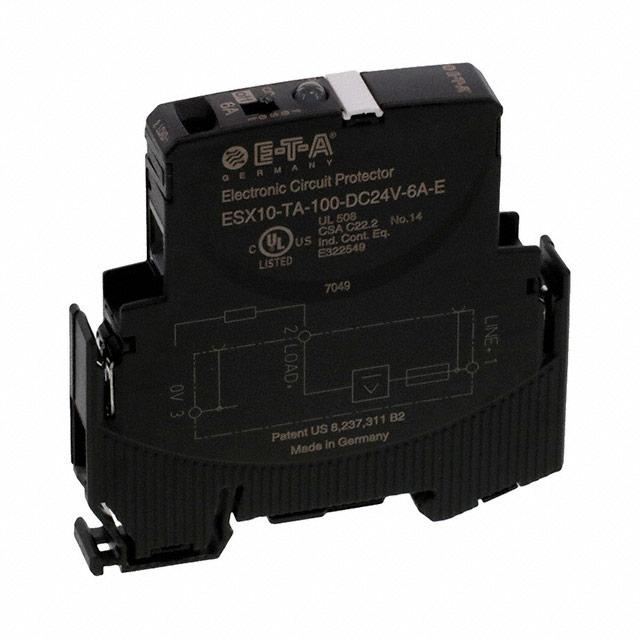


 工商网监
湘ICP备2023018690号
工商网监
湘ICP备2023018690号
