1N5820

1N5820

  • 厂商:

    WTE

  • 封装:

  • 描述:

    1N5820 - 3.0A SCHOTTKY BARRIER RECTIFIER - Won-Top Electronics

  • 详情介绍
  • 数据手册
  • 价格&库存
1N5820 数据手册
W TE PO WE R SEM IC O ND U C TO RS 1N5820 – 1N5822 3.0A SCHOTTKY BARRIER RECTIFIER Features ! ! ! ! ! ! Schottky Barrier Chip Guard Ring Die Construction for Transient Protection High Current Capability Low Power Loss, High Efficiency High Surge Current Capability For Use in Low Voltage, High Frequency Inverters, Free Wheeling, and Polarity Protection Applications A B A C D Mechanical Data ! ! ! ! ! ! Case: Molded Plastic Terminals: Plated Leads Solderable per MIL-STD-202, Method 208 Polarity: Cathode Band Weight: 1.2 grams (approx.) Mounting Position: Any Marking: Type Number DO-201AD Dim Min Max A 25.4 — B 8.50 9.50 C 1.20 1.30 D 5.0 5.60 All Dimensions in mm Maximum Ratings and Electrical Characteristics Single Phase, half wave, 60Hz, resistive or inductive load. For capacitive load, derate current by 20%. Characteristic Peak Repetitive Reverse Voltage Working Peak Reverse Voltage DC Blocking Voltage RMS Reverse Voltage Average Rectified Output Current (Note 1) @TL = 90°C Symbol VRRM VRWM VR VR(RMS) IO IFSM @TA=25°C unless otherwise specified 1N5820 20 14 1N5821 30 21 3.0 80 1N5822 40 28 Unit V V A A Non-Repetitive Peak Forward Surge Current 8.3ms Single half sine-wave superimposed on rated load (JEDEC Method) @TL = 75°C Forward Voltage Peak Reverse Current At Rated DC Blocking Voltage Typical Junction Capacitance (Note 2) Typical Thermal Resistance Junction to Ambient Operating and Storage Temperature Range @IF = 3.0A @IF = 9.4A @TA = 25°C @TA = 100°C VFM IRM Cj RJA Tj, TSTG 0.475 0.850 0.50 0.90 2.0 20 250 20 -65 to +150 0.525 0.950 V mA pF K/W °C Note: 1. Valid provided that leads are kept at ambient temperature at a distance of 9.5mm from the case. 2. Measured at 1.0 MHz and applied reverse voltage of 4.0V D.C. 1N5820 – 1N5822 1 of 3 © 2002 Won-Top Electronics 4 IF, INSTANTANEOUS FORWARD CURRENT (A) I(AV), AVERAGE OUTPUT CURRENT (A) Single Phase Half-Wave 60 Hz Resistive or Inductive Load 9.5mm Lead Length 30 3 10 2 1.0 1 Tj = 25ºC Pulse Width = 300µs 2% Duty Cycle 0 10 50 100 150 TL, LEAD TEMPERATURE (ºC) Fig. 1 Forward Current Derating Curve 0.1 0.1 0.3 0.5 0.7 0.9 1.1 VF, INSTANTANEOUS FORWARD VOLTAGE (V) Fig. 2 Typical Forward Voltage Characteristics 100 1000 IFSM , PEAK FORWARD SURGE CURRENT (A) Tj = 25ºC f = 1MHz 80 60 Cj, JUNCTION CAPACITANCE (pF) 100 40 20 8.3ms Single Half Sine-Wave JEDEC Method 0 1 10 NUMBER OF CYCLES AT 60 Hz Fig. 3 Peak Forward Sur g e Current 100 10 0.1 1.0 10 100 VR, REVERSE VOLTAGE (V) Fig. 4 Typical Junction Capacitance 1N5820 – 1N5822 2 of 3 © 2002 Won-Top Electronics ORDERING INFORMATION Product No.! 1N5820-T3 1N5820-TB 1N5820 1N5821-T3 1N5821-TB 1N5821 1N5822-T3 1N5822-TB 1N5822 Package Type DO-201AD DO-201AD DO-201AD DO-201AD DO-201AD DO-201AD DO-201AD DO-201AD DO-201AD Shipping Quantity 1200/Tape & Reel 1200/Tape & Box 500 Units/Box 1200/Tape & Reel 1200/Tape & Box 500 Units/Box 1200/Tape & Reel 1200/Tape & Box 500 Units/Box Products listed in bold are WTE Preferred devices. ! T3 suffix refers to a 13” reel. TB suffix refers to Ammo Pack. Shipping quantity given is for minimum packing quantity only. For minimum order quantity, please consult the Sales Department. Won-Top Electronics Co., Ltd (WTE) has checked all information carefully and believes it to be correct and accurate. However, WTE cannot assume any responsibility for inaccuracies. Furthermore, this information does not give the purchaser of semiconductor devices any license under patent rights to manufacturer. WTE reserves the right to change any or all information herein without further notice. WARNING: DO NOT USE IN LIFE SUPPORT EQUIPMENT. WTE power semiconductor products are not authorized for use as critical components in life support devices or systems without the express written approval. Won-Top Electronics Co., Ltd. No. 44 Yu Kang North 3rd Road, Chine Chen Dist., Kaohsiung, Taiwan Phone: 886-7-822-5408 or 886-7-822-5410 Fax: 886-7-822-5417 Email: sales@wontop.com Internet: http://www.wontop.com We power your everyday. © 2002 Won-Top Electronics 1N5820 – 1N5822 3 of 3
1N5820
1. 物料型号: - 1N5820-1N5822,3.0A肖特基势垒整流器。

2. 器件简介: - 该器件采用肖特基势垒芯片保护环结构,具有瞬态保护功能,适用于高电流、低功耗、高效率和高浪涌电流能力的应用。适用于低电压、高频逆变器、自由轮流通路和极性保护应用。
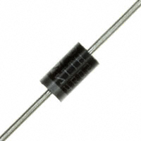
3. 引脚分配: - 封装类型为DO-201AD,具有镀锡引脚,可按照MIL-STD-202, Method 208进行焊接。极性标识为阴极带。

4. 参数特性: - 峰值重复反向电压、工作峰值反向电压、直流阻断电压分别为20V、30V、40V。RMS反向电压为14V、21V、28V。在90°C时,平均整流输出电流为3.0A。非重复峰值正向浪涌电流为80A(8.3ms单半正弦波叠加在额定负载上,JEDEC方法,75°C时)。正向电压在3.0A和9.4A时分别为0.475V、0.850V、0.50V、0.90V、0.525V、0.950V。额定直流阻断电压下峰值反向电流为2.0mA、20mA。典型结电容为250pF。典型热阻为20K/W。工作和存储温度范围为-65至+150℃。

5. 功能详解: - 该器件为单相、半波、60Hz、电阻性或感性负载设计。对于容性负载,电流需降低20%。

6. 应用信息: - 适用于低电压、高频逆变器、自由轮流通路和极性保护等应用。

7. 封装信息: - 封装类型为DO-201AD,重量约为1.2克,可任意位置安装,标记为型号编号。
1N5820 价格&库存

很抱歉,暂时无法提供与“1N5820”相匹配的价格&库存,您可以联系我们找货

免费人工找货