AC-DC
175 Watts
xppower.com
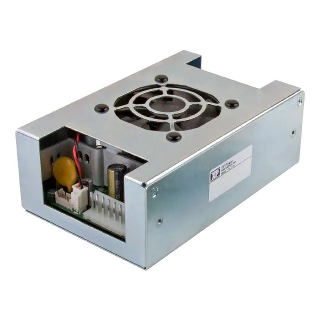
CLC Series
•
High Efficiency Resonant Topology
•
Medical Safety Approvals (-M Versions)
•
12 V Fan Output
•
Remote Sense
•
5V Standby Option
•
Remote On/Off & Power Good Signal Options
•
3 Year Warranty
Specification
Input
General
Input Voltage
• 85-264 VAC (120-370 VDC), derate output
power 10% 10 CFM
Operating Humidity
• 95% RH, non-condensing
Storage Temperature
• -40 °C to +85 °C
Operating Altitude
• 3000 m
Shock
• 30 g pk, half sine, 6 axes
Vibration
• 2 g rms, 5 Hz to 500 Hz, 3 axes
EMC & Safety
Low Voltage PSU EMC • EN61204-3, high severity level
Emissions
• EN55011/32 level B conducted
EN55011/32 level A radiated
Harmonic Currents
• EN61000-3-2, class A
Voltage Flicker
• EN61000-3-3
Radiated Immunity
• EN61000-4-3, level 3 Perf Criteria A
EFT/Burst
• EN61000-4-4, level 3 Perf Criteria A
Surge
• EN61000-4-5, installation class 3
Perf Criteria A
Conducted Immunity
• EN61000-4-6, level 3 Perf Criteria A
Dips & Interruptions
• EN61000-4-11, 30% 10 ms, 60% 100 ms,
100% 5000 ms Perf Criteria A, B, B
EN60601-1, 30% 500ms, 60% 100ms,
100% 10ms, 100% 5000ms (-M)
Perf Criteria A, A (with 50% load), A, B
Safety Approvals
• EN60601-1, ANSI/AAMI ES60601-1,
CSA22.2 No.60601-1 per cUL, Including
Risk Management, IEC60950-1:2005 Ed 2
/ IEC62368-1:2014
UL 62368-1 & CAN/CSA C22.2 No. 623681-14, EN62368-1:2014/A11:2017, CE &
UKCA meets all applicable directives &
legislation.
�Output Power(1)
Output Voltage V1
175 W
175 W
175 W
175 W
12.0 VDC
24.0 VDC
28.0 VDC
48.0 VDC
Fan Output
V2
Output Current V1
13.90
6.90
6.25
3.50
A
A
A
A
12.0 V/0.5
12.0 V/0.5
12.0 V/0.5
12.0 V/0.5
A
A
A
A
Standby Supply
V3 (optional)
5.0 V/0.5 A
5.0 V/0.5 A
5.0 V/0.5 A
5.0 V/0.5 A
Model Number(2,3)
CLC175US12
CLC175US24
CLC175US28
CLC175US48
(5)
Notes
1. 10 CFM airflow.
2. For medical version add, suffix ‘-M’ to model number.
3. For 5 V standby (V3), Power OK & Inhibit, add suffix ‘-A’ to model number.
4. For cover with Top Fan assembly add ‘-TF’ to model number e.g. CLC175US12-TF,
CLC175US12-ATF, CLC175US12-MTF or CLC175US12-MATF.
5. Not available for -A or -M.
Mechanical Details
5.00 (127.0)
0.22 (5.7)
1.30
(33.0)
4.55 (115.6)
0.20 (5.1)
Input Connector J1
Pin 1
Line
Pin 2
Neutral
0.25”Faston
Earth
3.00
(76.2)
1.90
(48.3)
0.61
(15.6)
1.11
(28.3)
0.23 (5.7)
0.20 (5.1)
4 x ø0.156 (3.96) Mounting Holes
ø0.312 (7.92) Clearance Top & Bottom
Fan Cover
J1 mates with Molex housing
09-50-1031 and Molex series
5194 crimp terminals.
2.50
(63.6)
2.55
(64.8)
0.25 Faston
Ground Tab
V Adj.
0.14
(3.5)
Pin
Pin
Pin
Pin
Pin
Pin
Pin
Pin
0.19 (4.8)
SMD component height
0.18
(4.6)
5.50 (139.7)
Output Connector J2
1
+V1
2
+V1
3
+V1
4
+V1
5
RTN
6
RTN
7
RTN
8
RTN
J2 mates with Molex housing
09-50-1081 and Molex series
5194 crimp terminals.
Input
Connector
3.50
(88.9)
0.25 (0.6)
Faston Ground Terminal
Output Connector
2.00
(50.7)
Signal Connector J3
Pin 1
+5V Standby
Pin 2
Logic GND
Pin 3
Logic GND
Pin 4
Power OK
Pin 5
Inhibit HI
Pin 6
Inhibit LO
Pin 7
+Sense
Pin 8
-Sense
Pin 9
+Vout
Pin 10
-Vout
J3 mates with JST housing
PHDR-10VS and JST SPHD001T-P0.5 crimp terminals.
4 x M3 x 0.5 THD
0.16 (4.0) Max Screw
Penetration
1.97
(50.0)
0.77 (19.5)
0.39 (9.9)
Pin 1
Pin 2
Fan Connector J4
Fan +(12V)
Fan -
J4 mates with Molex housing
22-01-1024 and Molex series 5103
crimp terminals.
4.724 (120.0)
Notes
2 x M3 x 0.5 THD
0.16 (4.0) Max Screw
Penetration
0.39 (9.9)
0.98 (25.0)
1. All dimensions in inches (mm).
Tolerance .xx = ±0.02 (0.50);
.xxx = ±0.01 (0.25)
2. Weight: 0.7 lbs (317 g) approx.
3. For thermal derating, please
refer to longform datasheet.
4.72 (120.0)
26 July 2022
AC-DC
CLC175
Models and Ratings
�
很抱歉,暂时无法提供与“CLC175US12-MTF”相匹配的价格&库存,您可以联系我们找货
免费人工找货