ECM40-60
•
40 & 60 Watt Models
•
Small Size 2.0”x 4.0”x 1.2”
•
Low Leakage Current
•
Industrial & Medical Approvals
•
Full Load Available Convection Cooled
•
Wide Operating Temperature 0 °C to +70 °C
•
Level B Conducted Emissions
•
EN61000 Compliant
•
Universal AC Input 90-264 VAC
•
Input Frequency 47-63 & 440 Hz
•
Single & Multiple Outputs
•
Cover Kits Available
•
Mating Connector & Loom Kits Available
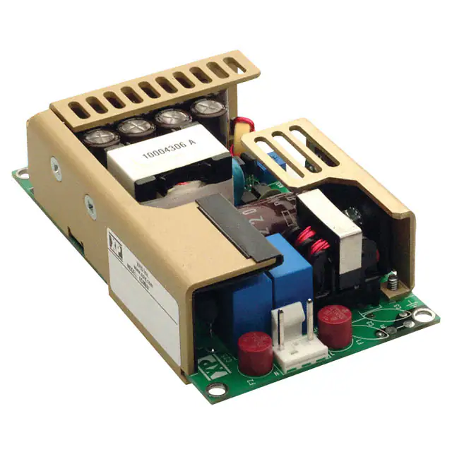
Approved for Class I and Class II applications, the ECM range of single and multiple output AC-DC, 40-60 W power supplies
from XP feature the world's smallest footprint for units of these ratings. Both are just 2" x 4" (50.8 mm x 101.6 mm) and 1.2"
(30.48 mm) high. Furthermore, these high-density power supplies meet EN55032 Level B conducted emissions with maximum
leakage currents of 100 µA at 115 VAC or 200 µA at 230 VAC. As a result, these switchers are equally suitable for industrial, IT
and medical applications, with no price premium for meeting medical requirements.
The ECM40-60 series have single output versions from 5 V to 48 VDC, adjustable by ±10%, and dual and triple output
versions covering combinations of 3.3 V, 5 V, 12 V, 15 V and 24 V. They are dual-fused for compliance with IEC60601-1 and
efficiency is 80-85%, depending upon the model, so minimal excess heat is generated.
The power supplies deliver full power between 0 °C and +50 °C and will operate at up to +70 °C with derating and only 5
CFM of cooling. Comprehensive overvoltage, overload and short circuit protection is built in. Covers, looms and connector kits
are available.
�xppower.com
Input Characteristics
Characteristic
Input Voltage - Operating
Input Frequency
Input Current - No load
Input Current - Full load
Inrush Current
Power Factor
Earth Leakage Current
Input Protection
Minimum
90
47
Typical
50/60
Maximum
264
63
41
1.38
40
Units
VAC
Hz
mA
A
A
290
µA
0.62
Notes & Conditions
120-370 VDC
400 Hz operation available
230 VAC
90 VAC
Cold start at 230 VAC
230 VAC
264 VAC
T3.15 A/ 250 V internal fuse in line & neutral
All specifications are at nominal input, full resistance load at 25°C unless otherwise stated.
Output Characteristics
Characteristic
Output Voltage
Initial Set Accuracy
Output Voltage Trim
Minimum load
Start Up Delay
Start Up Rise Time
Hold Up Time
Drift
Line Regulation
Load Regulation
Minimum
Typical
5.0
Maximum
Units
Notes & Conditions
48.0
V1: ±1, V2 & V3: ±5
See modules table
1.5
10
75
±0.2
±0.5
±1.0
V1: ±3, V2 & V3: ±5
VDC
%
%
A
s
ms
ms
%
%
%
%
4
%
1
135
170
%pk-pk
VDC
% Imax
0.05
%/ºC
±10
V1: 0.5, V2: 0.1
16
Transient Response
Ripple & Noise
Overvoltage Protection
Overload Protection
Short Circuit Protection
Temperature Coefficient
115
110
V1 (V2 will track V1 by the same %)
Not required on single output models
90 VAC
115-230 VAC input
90-264 VAC
Single output
Dual output
Output voltage recovers to within 1% in less
than 500 µs for 50% load change.
20 MHz bandwidth
Recycle input to reset
Auto-recovery
Trip & restart (hiccup mode)
General Specifications
Characteristic
Efficiency
Isolation Voltage
Switching Frequency
Power Density
Weight
MTBF
2
Minimum
Typical
Maximum
70
80
75
Units
%
(at 230 VAC
full load)
4000
1500
500
70
VAC
6.25
0.33 (150)
600
kHz
W/In3
lbs (g)
kHrs
Notes & Conditions
3.3 & 5 V single output versions
All other single output versions
Dual output versions
Input to output
Input to ground
Output to ground
Fixed
For 60 W version
Mil HDBK 217F
�xppower.com
Environmental
Characteristic
Operating Temperature
Storage Temperature
Cooling
Operating Humidity
Operating Altitude
Shock
Vibration
Minimum
Typical
Maximum
Units
Notes & Conditions
+70
+85
ºC
ºC
CFM
% RH
m
Gpk
G
See derating curves
-0
-40
0
95
3000
30
2
Convection-cooled
Non- condensing
Half sine 6 axis
5-500 Hz 3 axis
Electromagnetic Compatibility & Immunity
Standard
Test Level
EN55032
Emissions
Criteria
EN55032
Class A Radiated
EN60601-1-2
Class B Conducted
Harmonic Currents
EN61000-3-2
Voltage Flicker
EN61000-3-3
ESD Immunity
EN61000-4-2
level 2, performance criteria A
Radiated Immunity
EN61000-4-3
10 V/m, performance criteria A
EFT/Burst
EN61000-4-4
level 2, performance criteria A
Surge
EN61000-4-5
level 3, performance criteria A
Conducted Immunity
EN61000-4-6
10 Vrms, performance criteria A
70% UT : performance criteria A
Dips & Interruptions
Dips & Interruptions
EN61000-4-11
EN61000-4-11
(Medical)
Notes & Conditions
Class B Conducted
For 10 ms, 100% load
40% UT : performance criteria B
For 100 ms, 100% load
0% UT : performance criteria B
For 5000 ms, 100% load
70% Ut, performance criteria A
For 500 ms, Medical, 100% load
40% Ut, performance criteria A
For 100 ms, Medical, 60% load
0% Ut, performance criteria A
For 10 ms, Medical, 100% load
0% Ut, performance criteria B
For 5000 ms, Medical, 100% load
Safety Approvals
Safety Agency
CB Report
UL
TUV
CE
Safety Agency
CB Report
UL
TUV
Primary to Secondary
Primary to Earth
Safety Standard
IEC60950-1:2005 Ed 2 / IEC62368-1:2014
UL 62368-1 & CAN/CSA C22.2 No. 62368-1-14
EN62368-1:2014/A11:2017
LVD
Safety Standard
Certificate #US/18293 & 18269/UL, IEC60601-1 Ed 3 Including Risk Management
UL File # E146893, ANSI/AAMI ES 60601-1:2005 & CSA C22.2 No. 60601-1:08
TUV Certificate # B12 01 57396 125, EN60601-1:2006
Means of Protection
1 x MOPP (Means of Patient Protection) Contact Sales for 2 x MOPP
1 x MOPP (Means of Patient Protection)
Category
Information Technology
Information Technology
Information Technology
Category
Medical
Medical
Medical
Category
IEC60601-1 Ed 3
Equipment Protection
Class
Safety Standard
Notes & Conditions
Class I & Class II
IEC60950-1:2005 Ed 2 / IEC62368-1:2014
See safety agency conditions of
acceptability for details
3
�xppower.com
Models & Ratings
Max
Power
40 W
Max
Power
60 W
V1
5.0 V
7.0 V
9.0 V
12.0 V
15.0 V
18.0 V
24.0 V
33.0 V
48.0 V
+5.0 V
+5.0 V
+5.0 V
+5.0 V
+5.0 V
+3.3 V
+5.0 V
V1
5.0 V
7.0 V
9.0 V
12.0 V
15.0 V
18.0 V
20.0 V
24.0 V
28.0 V
33.0 V
48.0 V
+5.0 V
+5.0 V
+5.0 V
+5.0 V
+5.0 V
+3.3 V
+5.0 V
Imin/Imax(3)
0.0 A / 8.0 A
0.0 A / 5.7 A
0.0 A / 4.4 A
0.0 A / 3.5 A
0.0 A / 2.7 A
0.0 A / 2.2 A
0.0 A / 1.7 A
0.0 A / 1.2 A
0.0 A / 0.9 A
0.5 A / 6.0 A
0.5 A / 6.0 A
0.5 A / 6.0 A
0.5 A / 6.0 A
0.5 A / 6.0 A
0.5 A / 6.0 A
0.5 A / 6.0 A
Imin/Imax(3)
0.0 A / 12.00 A
0.0 A / 8.60 A
0.0 A / 6.70 A
0.0 A / 5.00 A
0.0 A / 4.00 A
0.0 A / 3.30 A
0.0 A / 3.00 A
0.0 A / 2.50 A
0.0 A / 2.14 A
0.0 A / 1.80 A
0.0 A / 1.25 A
0.5 A / 8.00 A
0.5 A / 8.00 A
0.5 A / 8.00 A
0.5 A / 8.00 A
0.5 A / 8.00 A
0.5 A / 8.00 A
0.5 A / 8.00 A
V2
Outputs
Imin/Imax
V3
+12.0 V
+15.0 V
+12.0 V
+24.0 V
+15.0 V
+5.0 V
+3.3 V
0.1
0.1
0.1
0.1
0.1
0.1
0.1
-12.0 V
-12.0 V
-15.0 V
+12.0 V
+12.0 V
V2
+12.0 V
+15.0 V
+12.0 V
+24.0 V
+15.0 V
+5.0 V
+3.3 V
A
A
A
A
A
A
A
/
/
/
/
/
/
/
2.0
1.5
2.0
1.0
1.5
1.5
1.5
Outputs
Imin/Imax
0.1
0.1
0.1
0.1
0.1
0.1
0.1
A
A
A
A
A
A
A
/
/
/
/
/
/
/
3.0
2.5
3.0
1.5
2.5
1.5
1.5
A
A
A
A
A
A
A
A
A
A
A
A
A
A
Imin/Imax
0.0
0.0
0.0
0.0
0.0
V3
-12.0 V
-12.0 V
-15.0 V
+12.0 V
+12.0 V
0.0
0.0
0.0
0.0
0.0
Notes
4
*Available from Newark InOne.
/
/
/
/
/
0.5
0.5
0.5
0.5
0.5
A
A
A
A
A
Imin/Imax
1. V2 will track a change in V1 by the same percentage change in voltage as V1 is trimmed.
2. To receive unit with cover fitted, add suffix ‘-C’ to model number. For Class I operation only.
3. A 120% peak load can be taken for up to 100 ms with a 25% duty cycle. Average load not to exceed maximum power rating.
† Available from Farnell InOne.
A
A
A
A
A
A
A
A
A
A
/
/
/
/
/
0.5
0.5
0.5
0.5
0.5
A
A
A
A
A
Model
Number
ECM40US05†*
ECM40US07
ECM40US09*
ECM40US12†*
ECM40US15†*
ECM40US18
ECM40US24†*
ECM40US33
ECM40US48†*
ECM40UD21
ECM40UD22
ECM40UT31†*
ECM40UT32†
ECM40UT33†*
ECM40UT34†*
ECM40UT35†
Model
Number
ECM60US05†*
ECM60US07
ECM60US09*
ECM60US12†*
ECM60US15†*
ECM60US18
ECM60US20
ECM60US24†*
ECM60US28
ECM60US33
ECM60US48†*
ECM60UD21
ECM60UD22
ECM60UT31†*
ECM60UT32†
ECM60UT33†*
ECM60UT34†*
ECM60UT35†
�xppower.com
Thermal Derating Curves
All ECM40 models with 5 CFM
100%
100%
75%
75%
Output Power
Output Power
All ECM40 models convection-cooled
50%
25%
50%
25%
0%
0%
0
10
20
30
40
50
60
Ambient Temp (°C)
70
0
80
30
20
50
40
60
80
70
Ambient Temp (°C)
Note: Derate by 10% if cover is fitted
All ECM60 models convection-cooled
All ECM60 models with 5 CFM
100%
Output Power
100%
Output Power
10
75%
50%
25%
75%
50%
25%
0%
0%
0
10
20
30
40
Ambient Temp (°C)
50
60
70
80
0
Note: Derate by 10% if cover is fitted
10
20
30
40
50
60
70
80
Ambient Temp (°C)
Transient Response
ECM60US24 25% load change
5
�xppower.com
Efficiency Versus Input Voltage
ECM60US24 with 60 W load
ECM60UT33 with 50 W load
Efficiency Versus Output Load
ECM60US24 at 230 VAC input
6
ECM60UT33 at 230 VAC input
�xppower.com
Start Up Delay
ECM60US24 with 60 W load
ECM60UT33 with 60 W load
Hold Up Tme
ECM60US24 with 60 W load at 230 VAC
Overload Characteristics
ECM60US24. When current reaches 5.4 A, output
goes into trip and restart (hiccup) mode
7
�xppower.com
Ripple & Noise
8
ECM60US24 with 60 W load
Noise measured is 64 mV pk-pk
ECM60UT33 output 1 with 30 W load.
Noise measured is 36 mV pk-pk
ECM60UT33 output 2 with 15 W load.
Noise measured is 68 mV pk-pk
ECM60UT33 output 3 with 7 W load.
Noise measured is 34 mV pk-pk
�xppower.com
Conducted Noise
ECM60US24 at full load
ECM60UT33 at full load
9
�xppower.com
Mechanical Details - Single Output Models
Weight: approx. 0.33 lb (150g)
1.20
(30.5)
4.00 (101.6)
3.75 (95.25)
CR2
J1
1
2
2.00
(50.8)
1
1.75
(44.45)
T1
J2
C4
L1
0.25 x 0.32 faston ground tab
4X ø0.156 (3.96) mounting holes
ø0.312 (7.92) clearance top and bottom
Input Connector J1
Pin 1
Line
Pin 2
Neutral
J1 mates with Molex housing 43061-0003
and Molex series 5194 crimp terminals.
Ground (0.25 faston) tab standard.
V Adj.
6
0.14 (3.5)
SMD component height
Output Connector J2
Single
Pin
1
+V1
2
+V1
3
RTN
4
RTN
5
N.C.
6
N.C.
J2 mates with Molex housing 43061-0006
& Molex series 5194 crimp terminals.
Notes
1. All dimensions in inches (mm). Tolerance .xx = ±0.02 (0.50); .xxx = ±0.01 (0.25)
2. Cable harnesses with 300mm wire available.
For single output models, order part number ECM40/60S LOOM.
For multi-output models, order part number ECM40/60DT LOOM .
3. Mating connector kit available. Order part number ECM40/60 CONKIT.
4. Covers available. Order part number ECM40/60 COVER. Cover dimensions are 4.49 x 2.52 x 1.52 (114 x 64 x 38.5)
5. † All accessories available from Farnell InOne.
Thermal Considerations
To ensure correct and safe operation of the PSU, the temperature of the components listed in the table below must not be exceeded. See
mechanical details for component locations.
Component
L1
T1
CR2
C4
10
Maximum Temperature
110 °C
110 °C
120 °C
95 °C
�xppower.com
Mechanical Details - Single Output Models (3 x 5)
Weight: approx. 0.4 lb (180 g)
1.20 (30.5)
0.14 (3.6), SMD Component Height
5.00 (127.0)
0.22 (5.71)
1
4.55 (115.57
N
L
J2
J1
3.00 (76.2)
6
2.55 (64.7)
P1
0.22 (5.71)
0.25 (6.35) Faston Ground Tab, Optional
4 x ø0.156 (3.96) Mounting Holes
ø0.312 (7.92) Clearance Top & Bottom
Input Connector J1
Pin 1
Line
Pin 2
Neutral
J1 mates with Molex housing 43061-0003
and Molex series 5194 crimp terminals.
Ground (0.25 faston) tab standard.
Output Connector J2
Single
Pin
1
+V1
2
+V1
3
RTN
4
RTN
5
N.C.
6
N.C.
J2 mates with Molex housing 43061-0006
& Molex series 5194 crimp terminals.
Notes
1. All dimensions in inches (mm). Tolerance .xx = ±0.02 (0.50); .xxx = ±0.01 (0.25)
2. Cable harnesses with 300mm wire available.
For single output models, order part number ECM40/60S LOOM.
For multi-output models, order part number ECM40/60DT LOOM .
3. Mating connector kit available. Order part number ECM40/60 CONKIT.
4. Covers available. Order part number ECM40/60 COVER. Cover dimensions are 4.49 x 2.52 x 1.52 (114 x 64 x 38.5)
5. † All accessories available from Farnell InOne.
Thermal Considerations
To ensure correct and safe operation of the PSU, the temperature of the components listed in the table below must not be exceeded. See
mechanical details for component locations.
Component
L1
T1
CR2
C4
Maximum Temperature
110 °C
110 °C
120 °C
95 °C
11
�xppower.com
Mechanical Details - Multi Output Models
Weight: approx. 0.33 lb (150g)
1.20
(30.5)
4.00 (101.6)
CR2
3.75 (95.25)
J1
2
2.00
(50.8)
1
1
1.75
(44.45)
T1
C4
L1
6
4X ø0.156 (3.96) mounting holes
ø0.312 (7.92) clearance top and bottom
Input Connector J1
Pin 1
Line
Pin 2
Neutral
J1 mates with Molex housing 43061-0003
and Molex series 5194 crimp terminals.
Ground (0.25 faston) tab standard.
J2
0.14 (3.5)
SMD component height
Output Connector J2
Single
Pin
1
+V1
2
+V1
3
RTN
4
RTN
5
-V3
6
+V2
J2 mates with Molex housing 43061-0006
& Molex series 5194 crimp terminals.
Notes
1. All dimensions in inches (mm). Tolerance .xx = ±0.02 (0.50); .xxx = ±0.01 (0.25)
2. Cable harnesses with 300mm wire available.
For single output models, order part number ECM40/60S LOOM.
For multi-output models, order part number ECM40/60DT LOOM .
3. Mating connector kit available. Order part number ECM40/60 CONKIT.
4. Covers available. Order part number ECM40/60 COVER. Cover dimensions are 4.49 x 2.52 x 1.52 (114 x 64 x 38.5)
5. † All accessories available from Farnell InOne.
Thermal Considerations
To ensure correct and safe operation of the PSU, the temperature of the components listed in the table below must not be exceeded. See
mechanical details for component locations.
Component
L1
T1
CR2
C4
12
Maximum Temperature
110 °C
110 °C
120 °C
95 °C
17 Feb 20
�ECM100 Series
•
100 Watt Models
•
Small Size 2.5” x 4.5” x 1.2”
•
Low Leakage Current
•
Industrial & Medical Approvals
•
Convection & Force Cooled Ratings
•
Wide Operating Temperature 0 °C to +70 °C
•
Level B Conducted Emissions
•
EN61000 Compliant
•
Universal AC Input 90-264 VAC
•
Input Frequency 47-63 & 440 Hz
•
Cover Kits Available
•
Mating Connector & Cable Harness Kits Available
Approved for Class I and Class II applications, the ECM100 range of single output AC-DC, 100 W power supplies from XP feature the
world's smallest footprint for units of these ratings. Size is just 2.5" x 4.5" (63.5 mm x 114.3 mm) and 1.2" (30.48 mm) high.
Furthermore, these high-density power supplies meet EN55032 Level B conducted emissions with maximum leakage currents of
125 µA at 115 VAC or 210 µA at 230 VAC. As a result, these switchers are equally suitable for industrial, IT and medical applications,
with no price premium for meeting medical requirements.
The ECM100 series have single output versions from 3.3 V to 48 VDC, adjustable by ±10%. They are dual-fused for compliance with
IEC60601-1 and efficiency is 80-85%, depending upon the model, so minimal excess heat is generated.
The power supplies deliver full power between 0 °C and +50 °C and will operate at up to +70 °C with derating and only 5 CFM
of cooling. Comprehensive overvoltage, overload and short circuit protection is built in. Covers, cable harnesses and connector kits
are available.
�xppower.com
Input Characteristics
Charactristic
Input Voltage - Operating
Input Frequency
Power Factor
Input Current - No Load
Input Current - Full Load
Inrush Current
Earth Leakage Current
Input Protection
Minimum
90
47
Typical
Minimum
Typical
50/60
0.62
40
0.9
Maximum
264
63
Units
VAC
Hz
Notes & Conditions
120-370 VDC
400 Hz operation available
230 VAC
mA
230 VAC
A
230 VAC
40
A
230 VAC cold start
125/210
µA
115/230 VAC
T3.15 A/250 V internal fuse in both line and neutral
Output Characteristics
Charactristic
Output Voltage
Initial Set Accuracy
Output Voltage Adjustment
Minimum Load
Start Up Delay
Start Up Rise Time
Hold Up Time
Drift
Line Regulation
3.3
Units
Notes & Conditions
48.0
V1: ±1. V2,V3 & V4: ±5
VDC
%
See Models and Ratings Table
±5
±10
%
1.5
50
75
±0.2
±0.5
±1
V1 & V2: ±1. V3 & V4: ±5
16
Load Regulation
Transient Response
Ripple & Noise
Overvoltage Protection
Overload Protection
Short Circuit Protection
Temperature Coefficient
Maximum
115
110
A
s
ms
ms
%
%
%
4
%
1
135
170
%pk-pk
%
%
0.05
%/˚C
3.3 & 5 V versions
All other versions
See model tables
90 VAC
115-230 VAC input
90-264 VAC
Single output versions
Multi output versions
Recovery to within 1% in less than 500 µs
for a 25% load change
20 MHz bandwidth
V1 only. Recycle input to reset
Primary power limit, auto-recovery
Trip & restart (Hiccup mode)
General Specifications
Characteristic
Reliability and Service Life
Isolation
Input to Output Test Voltage
Input to Ground Test Voltage
Output to Ground Test Voltage
Other Specifications
Efficiency
Switching Frequency
Weight
Minimum
Typical
4000
1500
500
80-85
70
0.4 (180)
Power Density
MTBF
2
Maximum
7.40
600
Units
Notes & Conditions
VAC
VAC
VAC
Test duration: 1 min
Test duration: 1 min
Test duration: 1 min
%
kHz
lb (g)
See Efficiency Graphs
Fixed
W/In3
kHrs
MIL HDBK 217F
�xppower.com
Environmental
Characteristic
Operating Temperature
Storage Temperature
Cooling
Humidity
Operating Altitude
Shock
Vibration
Minimum
0
-40
5
Typical
Maximum
+70
+85
95
3000
30
2
Units
˚C
˚C
CFM
%RH
m
G peak
G rms
Notes & Conditions
See derating curves
For full power operation
Non-condensing
Half sine 6 axis
5 Hz to 500 Hz, 3 axis
Electromagnetic Compatibility - Immunity
Phenomenon
Standard
Test Level
Criteria
ESD
EFT
Radiated Field
Surges
Conducted
EN61000-4-2
EN61000-4-4
EN61000-4-3
EN61000-4-5
EN61000-4-6
Dips and Interruptions
EN61000-4-11
(Medical)
Dips and Interruptions
EN61000-4-11
3
3
10 V/m
3
10 Vrms
70% Ut
40% Ut
0% Ut
0% Ut
70% Ut
40% Ut