Z02205
MODEM CONTROLLER IDEAL FOR LOW POWER
CONSUMPTION, SMALL SIZE REQUIREMENTS
PRODUCT SPECIFICATION
PS001000-MOD0599
ZiLOG WORLDWIDE HEADQUARTERS • 910 E. HAMILTON AVENUE • CAMPBELL, CA 95008
TELEPHONE: 408.558.8500 • FAX: 408.558.8300 • INTERNET: HTTP://WWW.ZILOG.COM
�©1999 by ZiLOG, Inc. All rights reserved. Information in this publication concerning the devices, applications, or technology described is intended to suggest possible uses and may be superseded. ZiLOG, INC.
DOES NOT ASSUME LIABILITY FOR OR PROVIDE A REPRESENTATION OF ACCURACY OF
THE INFORMATION, DEVICES, OR TECHNOLOGY DESCRIBED IN THIS DOCUMENT. ZiLOG
ALSO DOES NOT ASSUME LIABILITY FOR INTELLECTUAL PROPERTY INFRINGEMENT
RELATED IN ANY MANNER TO USE OF INFORMATION, DEVICES, OR TECHNOLOGY
DESCRIBED HEREIN OR OTHERWISE. Except with the express written approval of ZiLOG, use of
information, devices, or technology as critical components of life support systems is not authorized. No
licenses are conveyed, implicitly or otherwise, by this document under any intellectual property rights.
ii
Z02205
PS001000-MOD0599
�PRODUCT SPECIFICATION
Z02205
1
MODEM CONTROLLER IDEAL FOR LOW POWER
CONSUMPTION, SMALL SIZE REQUIREMENTS
FEATURES
Device
ROM
(KB)
RAM*
(Bytes)
Speed
(MHz)
Z02205
16
237
16
Includes AT command set interpreter in on-chip ROM—
no external memory required
Supports Tone dial or Pulse dial
Call progress monitoring controls
Handshake controls
Guard Tone controls
Line quality monitoring and Auto-Retrain
Auto-Dial and Auto-Answer
Glueless interface to Z02201 modem data pump
Watch-Dog Timer (WDT)/Power-On Reset (POR)
Type-I Caller ID
Dynamic power management
CMOS design for low power consumption
0°C to +70°C commercial temperature range
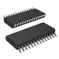
28-pin DIP, SOIC package
4.5V to 5.5V operating range
GENERAL DESCRIPTION
The Z02205 V.22bis Modem Controller serves as the modem controller in embedded V.22bis modem applications.
A complete modem can be made by adding ZiLOG data
pump (Z02201), phone line interface, and the required DTE
interface. The Z02205 has been designed for low-cost use
and includes a glueless interface to the ZiLOG data pumps.
The Z02205 is ideal for applications where small size and
low power consumption are requirements.
The Z02205 operates over dial-up telephone connections,
provides auto-dial and ring detect, and operates in either
SYNC or ASYNC modes.
The Z02205 includes AT command and modem control
firmware in on-chip ROM. It also includes enhanced wakeup circuitry, programmable Watch-Dog Timers (WDT), and
low-noise/EMI options.
AT commands stored on-chip in ROM provide control over
the following modem controller functions:
PS001000-MOD0599
Call progress monitoring
Handshake negotiation
Dial controls—pulse or tone
S-registers
Auto-answer and auto-dial
Guard tones
On-hook and off-hook
Auto-retrain
Standard Z02205 sample devices and demonstration boards
contain controller code tailored for operation on the North
American phone network. For production usage, customers
must modify the controller code to meet the requirements
of their particular country and application.
1
�Z02205
Modem Controller
ZiLOG
Note: All signals with an overline, are active Low. For example, B/W, in which WORD is active Low; and B/W, in
which BYTE is active Low.
Power connections follow conventional descriptions below:
Parallel
DTE
Z02205
Controller
Connection
Circuit
Device
Power
VCC
VDD
Ground
GND
VSS
Line
Interface
Z02201
or
Z02922
Data Pump
Serial
Data
Access
Arrangement
Telephone
Line
Speaker
Optional
Eye Pattern
Interface
Oscilloscope
Optional
Optional
Figure 1. Functional Block Diagram
D5
D6
D7
DPRD
DPWR
DPRESET
MUTE
VCC
XTAL2
XTAL1
DPIRQ
RINGDET
DTR
DCD
1
28
Z02205
14
15
D4
D3
D2
D1
D0
DPCS
GND
A2
A1
A0
RxD
OH
TxD
SHUNT
Figure 2. Z02205 Pin Diagram (SOIC/ DIP)
2
PS001000-MOD0599
�Z02205
Modem Controller
ZiLOG
PIN DESCRIPTION
Table 1. Z02205 Pin Identification
Pin #
Symbol
Function
Direction
1–3
D5–D7
DSP Register Data Lines 5 through 7
In/Output
4
DPRD
Data Pump Read
Output
5
DPWR
Data Pump Write
Output
6
DPRESET
Data Pump Reset
Output
7
MUTE
Speaker Mute
Output
8
VCC
Power Supply
9
XTAL2
Crystal Oscillator
Output
10
XTAL1
Crystal Oscillator
Input
11
DPIRQ
Data Pump Interrupt Request
Input
12
RINGDET
Ring Detect Input
Input
13
DTR
Data Terminal Ready
Input
14
DCD
Data Carrier Detect
Output
15
SHUNT
Pulse Dial Shunt Relay Output
Output
16
TxD
Data Transmit
Output
17
OH
Off Hook Relay Output
Output
18
RxD
Data Receive
Input
19–21
A0–A2
DSP Register Address Lines 0 through 2
Output
22
GND
Ground
23
DPCS
Data Pump Chip Select
Output
24–28
D0–D4
DSP Register Data Lines 0 through 4
In/Output
PS001000-MOD0599
3
�Z02205
Modem Controller
ZiLOG
ABSOLUTE MAXIMUM RATINGS
Min
Max
Units
0
+70
C
Storage Temperature
–65
+150
C
Voltage on any Pin with Respect to VSS
–0.6
+7
V
Voltage on VDD Pin with Respect to VSS
–0.3
+7
V
Voltage on XTAL1 and RESET Pins with Respect to VSS
–0.6
VDD+1
V
Total Power Dissipation
1.21
W
Maximum Allowable Current out of VSS
220
mA
Maximum Allowable Current into VDD
180
mA
Parameter
Ambient Temperature under Bias
Notes
1
2
Maximum Allowable Current into an Input Pin
–600
+600
µA
3
Maximum Allowable Current into an Open-Drain Pin
–600
+600
µA
4
Maximum Allowable Output Current Sinked by Any I/O Pin
25
mA
Maximum Allowable Output Current Sourced by Any I/O Pin
25
mA
Notes:
1. This applies to all pins except XTAL pins and where otherwise noted.
2. There is no input protection diode from pin to VDD and current into pin is limited to ±600 µA.
3. This excludes XTAL pins.
4. Device pin is not at an output Low state.
Stresses greater than those listed under “Absolute Maximum Ratings” may cause permanent damage to the device.
This rating is a stress rating only. Functional operation of
the device at any condition above those indicated in the operational sections of these specifications is not implied. ExTotal Power Dissipation =
4
posure to absolute maximum rating conditions for an extended period may affect device reliability.
Total power dissipation should not exceed 1.21 W for the
package. Power dissipation is calculated as follows:
VDD x [ IDD – (sum of IOH) ] = + sum of [ (VDD – VOH) x IOH] + sum of (V0L x I0L)
PS001000-MOD0599
�Z02205
Modem Controller
ZiLOG
STANDARD TEST CONDITIONS
The characteristics listed below apply for standard test conditions as noted. All voltages are referenced to GND. Positive current flows into the referenced pin (Figure 3).
From Output
Under Test
I
150 pF
Figure 3. Test Load Diagram
CAPACITANCE
TA = 25°C, VCC = GND = 0V, f = 1.0 MHz, Unmeasured pins to GND
Parameter
Input capacitance
Output capacitance
I/O capacitance
Min
Max
0
0
0
12 pF
12 pF
12 pF
DC ELECTRICAL CHARACTERISTICS
VCC
TA = 0° C to +70°C
Min
Max
Typical [1]
@ 25°C
Units
5.5V
0.7 VCC
VCC+0.3
2.6
V
5.5V
GND–0.3
0.2 VCC
2.1
V
5.5V
0.7 VCC
VCC+0.3
2.6
V
5.5V
GND–0.3
0.2 VCC
1.6
V
5.5V
VCC–0.4
4.8
V
IOH = –2.0 mA
8
IIL
Clock Input Low
Voltage
Input High
Voltage
Input Low
Voltage
Output High
Voltage
Output Low
Voltage
Output Low
Voltage
Comparator
Input Offset
Voltage
Input Leakage
5.5V
IOL
Output Leakage
5.5V
Sym
Parameter
VCH
Clock Input High
Voltage
VCL
VIH
VIL
VOH1
VOL1
VOL2
VOFFSET
PS001000-MOD0599
Note [3]
Conditions
Notes
Driven by
External Clock
Generator
Driven by External
Clock Generator
5.5V
0.4
0.1
V
IOL = +4.0 mA
8
5.5V
1.2
0.4
V
IOL = +12 mA
8
5.5V
25
10
mV
–1
2
0.004
µA
VIN = 0V, VCC
–1
1
0.004
µA
VIN = 0V, VCC
10
5
�Z02205
Modem Controller
ZiLOG
VCC
TA = 0° C to +70°C
Note [3]
Min
Max
Typical [1]
@ 25°C
Units
Reset Input
Current
Supply Current
5.5V
–20
–180
–85
µA
5.5V
25
20
mA
@ 16 MHz
ICC1
Standby Current
(HALT Mode)
5.5V
8
3.7
mA
ICC2
Standby Current
(STOP Mode)
5.5V
10
4
µA
5.5V
800
600
µA
VIN = 0V, VCC
@ 16 MHz
VIN = 0V, VCC WDT is
not Running
VIN = 0V, VCC WDT is
Running
Sym
Parameter
IIR
ICC
VICR
IALL
IALH
VLV
VOH
VOL
Input Common
Mode
Voltage Range
Auto Latch Low
Current
Auto Latch High
Current
VCC Low
Voltage
Protection
Voltage
Output High
Voltage
(Low EMI
Mode)
Output Low
Voltage
(Low EMI
Mode)
Conditions
4
4
6,11
6,11,
13
5.5V
0
VCC–1.0V
5.5V
1.4
15
5
µA
0V < VIN < VCC
9
5.5V
–1.0
–8
–6
µA
0V < VIN < VCC
9
2.8
V
7
2.2
5.0V
5.0V
3.1
VCC–0.4
0.4
V
Notes
10
4.8
V
4 MHz max Int. CLK
Freq.
6 MHz max Int. CLK
Freq.
IOH = –0.5 mA
0.1
V
IOL = 1.0 mA
2.8
7,13
Notes:
1. Typicals at VCC = 5.0V.
2. GND = 0V.
3. The VDD voltage specification of 5.5V guarantees 5.0V ±0.5V with typicals at VCC–5.0V.
4. All outputs unloaded, I/O pins floating, inputs at rail.
5. CL1 = CL2 = 10 pF.
6. Same as note [4] except inputs at VCC.
7. The VLV voltage increases as the temperature decreases and will overlap lower VCC operating region.
8. Standard Mode (not Low EMI).
9. Auto Latch (Mask Option) selected.
10. For analog comparator, inputs when analog comparators are enabled.
11. Clock must be forced Low, when XTAL1 is clock-driven and XTAL2 is floating.
12. Excludes clock pins.
13. 0°C to 70°C (standard temperature).
6
PS001000-MOD0599
�Z02205
Modem Controller
ZiLOG
AC ELECTRICAL CHARACTERISTICS
Additional Timing Diagram
3
1
Clock
2
7
2
3
7
TIN
4
5
6
IRQN
8
9
Clock
Setup
11
Stop
Mode
Recovery
Source
10
Figure 4. Additional Timing
PS001000-MOD0599
7
�Z02205
Modem Controller
ZiLOG
Additional Timing Table (SCLK/TCLK = XTAL/2)
No
Symbol
Parameter
1
TpC
Input Clock Period
2
3
TrC,TfC
TwC
Clock Input Rise & Fall Times
Input Clock Width
4
5
6
7
8A
8B
9
10
11
TwTinL
TwTinH
TpTin
TrTin, TfTin
TwIL
TwIL
TwIH
Twsm
Tost
Timer Input Low Width
Timer Input High Width
Timer Input Period
Timer Input Rise & Fall Timer
Int. Request Low Time
Int. Request Low Time
Int. Request Input High Time
Stop-Mode Recovery Width Spec
Oscillator Startup Time
12
Twdt
Watch-Dog Timer Delay Time
before time-out
13
TPOR
Power-On Reset Delay
Note
[3]
VCC
5.5V
5.5V
5.5V
5.5V
5.5V
5.5V
5.5V
5.5V
5.5V
5.5V
5.5V
5.5V
5.5V
5.5V
5.5V
5.5V
5.5V
5.5V
5.5V
TA = 0°C to +70°C
16 MHz
Min
Max
Units
Notes
62.5
250
DC
DC
15
ns
ns
ns
ns
ns
ns
100
ns
ns
1,7
1,8
1
1
1,8
1
1
1
1
1,2
1,3
1,2
31
125
70
5TpC
8TpC
70
5TpC
5TpC
12
ns
5TpC
3.5
7
14
56
1.5
13
4
ms
ms
ms
ms
ms
D1, D0
[Note]
0, 0 [5]
0, 1 [5]
1, 0 [5]
1, 1 [5]
Notes::
1. Timing Reference uses 0.7 V CC for a logic 1 and 0.2 VCC for a logic 0.
2. Interrupt request via Port 3 (P31–P33).
3. Interrupt request via Port 3 (P30).
4. SMR–D5 = 0.
5. Reg. WDTMR.
6. The VDD voltage specification of 5.5V guarantees 5.0V ± 0.5V.
7. Standard Oscillator mode, Pcon RegD7=1.
8. Maximum frequency for external XTAL Clock is 4MHz when using low EMI oscillator mode, Pcon Reg D7=0.
8
PS001000-MOD0599
�Z02205
Modem Controller
ZiLOG
PIN FUNCTIONS
XTAL1 Crystal 1 (Time-based Input).
DPRD Data Pump Read (Output).
XTAL2 Crystal 2 (Time-based Output).
D0–D7 DSP Register Data Lines (Input/Output).
DPWR Data Pump Write (Output).
A0–A2 DSP Register Address Lines (Output).
DPRESET Data Pump Reset (Output).
TxD Transmit Data (Output).
DPIRQ Data Pump Interrupt Request (Input).
RxD Read Data (Input).
DPCS Data Pump Chip Select (Output).
DTR Data Terminal Ready (Input).
OH Off Hook Relay Output (Output).
DCD Data Carrier Detect (Output).
SHUNT Pulse Dial Shunt Relay Output (Output).
MUTE Speaker Mute Control (Output).
RINGDET Ring Detect Input (Input).
PS001000-MOD0599
9
�Z02205
Modem Controller
ZiLOG
AT COMMAND SET
Command lines are typed to the modem from the terminal
when the modem is in the Idle or Command state. The modem does not execute any commands from a command line
until the command line is ended by the end of line character
. A command line is a string of characters starting with
A and T characters and ending with a special end-of-line
character, . Characters typed before the AT are ignored. Command lines contain no more than 40 characters
after the AT (not counting spaces). The modem does not execute any commands in a command line that is too long.
To Echo command line characters, use the E1 command.
Typing mistakes can be aborted by using a special BackSpace character, , after the initial A and T characters
are entered.
A partial command line can be aborted by typing a Ctrl-X
character. The modem returns an OK result code and ignores the partial AT command line.
Command lines may contain several commands one after
another. The ANSWER (A), DIAL (D), and GO ON-LINE (O)
commands cause any subsequent commands in the command line to be ignored.
Command Line Execution
The characters in a command line execute one at a time. Any
unexpected characters, except control characters, stop command line execution and return an ERROR result code. Unexpected characters include numbers outside the range of
values accepted by the command. All control characters in
a command line except Ctrl-X and the special characters
such as and are ignored.
The numerical argument of a command is assumed to be 0
if not provided. For example, the commands ATH and
ATH0 both hang up the telephone line.
When the modem has executed a command line, the result
code of the last command executed is returned to the terminal.
If the value to be written to a modem S-register is outside
the range of values accepted by the S-register, then its value
is set to the nearest allowed value.
Leading zeros in numeric arguments, including S-register
numbers, are ignored. For example, ATS1 is 2 and ATS01
is 2 both set S-register S1 to 2.
All numeric arguments, including S-register numbers, are
decimal.
AT Command Prefix
Each modem command line begins with the letters A and
T. The modem uses these characters to determine the data
rate and parity of data from the terminal.
A/ Repeat Last Command
To repeat the commands in the last command line, type the
letters A and / instead of A and T.
End Of Line Character
This character is typed to end a command line. The value
of the character is stored in S-register S3. The default
is 13, the ASCII carriage return character.
When the character is entered, the modem executes
the commands in the command line.
Note: Default values in Table 2 are denoted by bold.
.
10
PS001000-MOD0599
�Z02205
Modem Controller
ZiLOG
Table 2. AT Command Set
Command
A
B
&C
Function and Description
Answer
The A command causes the modem go off-hook and respond to an incoming call. Uses
this command after the modem has returned the RING result code.
When modems successfully complete the answering process, they each return a
CONNECT result code and enter the On-Line state.
If no transmit carrier signal is received from the calling modem within the time specified
in S-register S7, the modem hangs up, returns the NO CARRIER result code, and enters
the Idle state.
Any commands following the answer command on the command line are ignored.
This command is aborted if a key is pressed before the answer process is completed, or
when DTR is off, if some options in the &Q or &D commands have been used.
Communication Standard The B command indicates to the modem which special telephone line modulation
Option
standards to use. The modem can be configured to use:
B0
Uses the ITU-T modulation standards for all telephone line data rates. This
includes V.22 for the 1200 bps telephone line data rate and V.21 for the 300
bps telephone line data rate. If S-register S37 is set to 1 (or 2), then V.23 is
used with the originating modem transmitting at 75 bps and receiving at
1200 bps. If S-register S37 is set to any other value, V.23 is not used.
B1
If the 1200 bps telephone line data rate is required, Bell 212A is used
instead of V.22. This is the default value for North America. The 1200 bps
telephone line data rate is required only if:
• S-register S37 is set to 5, or
• S-register S37 is set to 0, and the terminal data rate is 1200 bps.
If the 300 bps telephone line data rate is required, Bell 103 is used instead
of V.21. The 300 bps telephone line data rate is required only if:
• S-register S37 is set to 3, or
• S-register S37 is set to 0 and the terminal data rate is 300 bps.
If neither the 1200 bps nor 300 bps telephone line data rate are required,
then a setting of B1 is ignored and the modem responds as if B0 was set.
B2
Same as B0 for the 1200 bps and 300 bps telephone line date rate. Uses
V.23 with the originating modem transmitting at 1200 bps and receiving at
75 bps, if S-register S37 is set to 1 or 2.
B3
Same as B0 for the 1200 bps and 300 bps telephone line date rate. Uses
V.23 with the originating modem transmitting at 75 bps and receiving at
1200 bps, if S-register S37 is set to 1 or 2.
Data Carrier Detect
&C determines how the modem’s DCD signal relates to the carrier signal from the other
Options
modem. This option occurs only at the beginning of a telephone line connection. If &C is
issued from the Command state, it will not have an immediate effect.
&C0
During asynchronous operation (&Q0 in effect), DCD is on at all times.
During synchronous operation (&Q1), DCD indicates the state of the
carrier signal from the other modem using S-registers S9 and S10. This is
the default value in North America.
&C1
Indicates the state of the carrier signal from the other modem using Sregisters S9 and S10.
PS001000-MOD0599
11
�Z02205
Modem Controller
ZiLOG
Table 2. AT Command Set (Continued)
Command
Function and Description
D
Dial
&D
Data Terminal Ready
Options
12
The D command causes the modem to dial a telephone call according to the digits and
dial modifiers in the dial string following the command. Any commands following the
dial string on a command line are ignored, unless the semicolon dial modifier is the last
character in the dial string. If the modem is off-hook when the Dial command is given,
the modem dials immediately without trying to detect a dial tone. Characters other than
digits and dial modifiers in a dial string are ignored; however, they are counted as
characters in the command line buffer.
If line current sensing is enabled, and line current is detected before the modem is taken
OFF-HOOK when the modem dials, a NO CARRIER result code is displayed and the
modem enters the IDLE state. If the modem needs not dial (that is, ATD with no dial
string), the modem assumes the call was manually established and attempts to make a
connection.
The D command is not valid when the modem is in the On-Line state.
See “Dial Modifiers and “Modem Result Codes for more information.
&D determines how the modem responds to the DTR signal from the terminal. The
country configuration may prevent the modem from detecting terminal DTR. In this
case, the modem assumes DTR is always on. In North America, terminal DTR is
normally detected. If DTR detection has been prevented, the modem will respond with
an ERROR result to this command.
The response to changes in DTR also depends on the &Q and &D commands. This table
defines what happens when DTR goes off for all possible combinations of the &D and
&Q commands. To see what happens when DTR goes on, refer to the &Q command. The
default value is &D0 in North America:
&D0
&D1
&D2
&D3
&Q0
None
B
C
D
&Q1
A
B
C
D
A
The modem hangs up the telephone line and issues an OK result code.
B
If in the On-Line state, the modem goes into the Command state, and issues
an OK result code.
C
The modem hangs up the telephone line and issues an OK result code.
Auto-Answer is disabled as long as DTR stays off.
D
The modem resets.
PS001000-MOD0599
�Z02205
Modem Controller
ZiLOG
Table 2. AT Command Set (Continued)
Command
Function and Description
E
Command Mode
Character Echo
%E
Automatic Retrain
Options
&F
Recall Factory Profile
&G
Guard Tone Options
H
Hook
PS001000-MOD0599
E tells the modem to echo or not echo characters sent from the terminal while the modem
is accepting AT commands.
E0
Does not echo characters sent from the terminal.
E1
Echo characters sent from the terminal. This is the default value in North
America.
The %E command controls whether the modem will initiate retrain with the other
modem during a telephone line connection during operation in data modes supporting
retrain. The modem always responds to a retrain operation initiated by the remote
modem. The modem can be forced to initiate a retrain by the On-Line (O1) command.
%E0
Do not initiate a retrain.
%E1
Initiate a retrain if the datapump indicates that one is required.
&F changes these AT command options and S-registers to default
values. The default values may be changed for use in different countries. The values for
North America are:
S-registers
S0=0
S1=0
S2=43
S3=13
S4=10
S5=8
S6=2
S7=30
S8=2
S9=6
S10=14
S11=95
S12=50
S17=10
S25=5
S28=0
S29=25
S37=0
Commands
B1 E1 M1 P Q0 V1 X4 &C0 &D0 &G0 &P0 &Q0 %E1
&G indicates the modem which guard tone to transmit when the modem is transmitting
the high band (that is, answer handshake and answer mode).
&G0
No guard tone. This is the default value in North America.
&G1
550-Hz guard tone (V.22 and V.22bis only)
&G2
1800-Hz guard tone (V.22 and V.22bis only)
H0
Hangs up the telephone line.
H1
Goes off hook without answering a telephone call. This may be disabled in
countries prohibiting its use.
13
�Z02205
Modem Controller
ZiLOG
Table 2. AT Command Set (Continued)
Command
Function and Description
&HT
PTT Test Command
I
Identification
14
The &HT command causes the modem to transmit tones for PTT testing. The test tone is
generated until a character is typed on the modem’s terminal. The country configuration
may disable this command. The modem returns an
ERROR result if this command
is issued.
&HT0-9
DTMF tone for digit n where the command was &HTn.
&HT10
DTMF tone"*"
&HT11
DTMF tone "#"
&HT12
DTMF tone "A"
&HT13
DTMF tone "B"
&HT14
DTMF tone "C"
&HT15
DTMF tone "D"
&HT16
V.21 channel 1 mark
&HT17
V.21 channel 2 marks
&HT18
V.23 1200bps marks
&HT19
V.23 75bps marks
&HT20
V.21 channel 1 spaces
&HT21
V.21 channel 2 spaces
&HT22
V.23 1200bps spaces
&HT23
V.23 75bps spaces
&HT24
V.22 originate mode
&HT25
V.22 answer mode
&HT26
V.22bis originate mode
&HT27
V.22bis answer mode
&HT28
V.25 calling tone
&HT29
550Hz guard tone
&HT30
1800Hz guard tone
&HT31
Silence
&HT32
Detect 2100 Hz answer tone
&HT33
Detect all supported answer tones simultaneously
&HT34
Detect dial tone
&HT35
Detect call progress tones
The I command queries the modem for information that can be used to determine the
modem’s compatibility with other software and to ensure the modem is operating
properly.
I0
Displays product code. The modem reports its product code to the terminal.
The modem produces information text dependent upon its features and
capabilities.
I1
Displays ROM checksum. The modem reports the value of its ROM
checksum. The decimal number displayed is the eight bit sum (from 0 to
255) of all the bytes in ROM.
I2
Tests the ROM checksum. The modem checks its ROM to ensure it is
correct. The modem reports a result code indicating whether the ROM is
OK or in ERROR.
I3
Displays Software Versions. The modem reports the modem controller and
data pump software versions, and the modem controller software release
date, to the terminal.
I4
Displays Modem Identification. The modem reports a configured
identification message to the terminal.
PS001000-MOD0599
�Z02205
Modem Controller
ZiLOG
Table 2. AT Command Set (Continued)
Command
M
O
&P
Q
&Q
Sn
?
=x
T
V
Function and Description
Speaker On/Off Options
The country configuration may disable the speaker. If so, this command returns an
ERROR result.
M0
Speaker always off.
M1
Speaker on until carrier detected. This is the default value in North
America.
M2
Speaker always on; stays on after carrier is detected.
M3
Speaker off as digits are dialled, but on during ringback and on until carrier
signal is detected.
Return to On-Line
This command returns the modem to the on-line mode. It is frequently used after the
Mode
escape character sequence (+++) to resume communication with the remote modem. If
handshaking is started, the modem uses Originate or Answer mode handshaking,
depending upon whether the modem originated or answered the telephone call.
O0
Returns the modem to the On-Line state from the Command state during a
telephone line connection. The modem starts handshaking if no telephone
line connection and the modem was off hook.
O1
Returns the modem to the On-Line state and retrain its data pump during a
telephone line connection. The modem starts handshaking if there was no
telephone line connection is detected but the modem was OFF-HOOK.
Pulse Dial Make/Break
Sets cadence of pulse dial. The country configuration may disable this command,
Ratios
forcing particular pulse dialing parameters. In this event, the modem returns an ERROR
result if this command is issued.
&P0
39%/61% make/break ratio and 10 pulses per second when pulse dialing.
This is the default value.
&P1
33%/67% make/break ratio and 10 pulses per second when pulse dialing.
&P2
39%/61% make/break ratio and 20 pulses per second when pulse dialing.
&P3
33%/67% make/break ratio and 20 pulses per second when pulse dialing.
Result Code Display
This command allows the user to either display result codes or to not display result
Options
codes.
Q0
Result codes are displayed. This is the default value for North America.
Q1
Result codes are not displayed.
Communications Mode The &Q command selects the terminal communication mode.
Options
&Q0
Asynchronous. The modem handshakes as the originator if S-register S0
is 0, and as the answerer if S0 is 1. This is the default value for North
America.
&Q1
Synchronous. Hangs up if DTR goes from on to off after the time in Sregister S25 after the CONNECT result code has been sent to the terminal.
Set the current S-register This command sets the current S-register to the value n selected by the user. For
to n
example, ATS7 will set the current S-register to S7. Default value is 0. Sn addresses a
particular S-register number so future commands like? and = will read of write the Sregister. Modem reset and the &F command select S0 as the default S-register.
Read an S-Register
This command displays the value of the last S-register named in the Sn command.
Write an S-register
This command writes the value x to the last S-register named in the Sn command. The
range of valid values for x depends upon which S-register is being written. 0 is assumed
if no value is given for x.
Tone dialing
Selects the tone method of dialing.
Result Code Format
This command changes the result code display format
V0
All result codes are displayed as numbers.
V1
All result codes are displayed as words (verbose form). This is the default
value for North America.
PS001000-MOD0599
15
�Z02205
Modem Controller
ZiLOG
Table 2. AT Command Set (Continued)
Command
X
Function and Description
Call Progress
#CID= Caller Id Options
The X command controls whether or not a busy signal or dial tone is detected when
dialing. The X command also limits the result codes the modem returns when dialing.
The operation of the X command is configurable for operation in different countries.
X0
Neither busy signal nor dial tone are detected. When a telephone line
connection is made, the result code does not indicate the telephone line data
rate.
X1
Neither busy signal nor dial tone are detected. When a telephone line
connection is made, the result code indicates the telephone line data rate.
X2
Busy signal is not detected. Dial tone is detected. When a telephone line
connection is made, the result code indicates the telephone line data rate.
X3
Busy signal is detected. Dial tone is not detected. When a telephone line
connection is made, the result code indicates the telephone line data rate.
X4
Both busy signal and dial tone are detected. When a telephone line
connection is made, the result code indicates the telephone line data rate.
This is the default value in North America.
The @ and W dial modifiers are not affected by the X command. The @ dial modifier
may return the result codes 8 (NO ANSWER) or 7 (BUSY) each time it appears in the
dial string. The W dial modifier may return the result codes 6 (NO DIALTONE) or 7
(BUSY) each time it appears in the dial string.
The #CID= command controls how the modem displays
North American caller identification information. The #CID=
command is valid only if the Modem Controller software has
been compiled to support Caller ID. If the software has not
been compiled to support Caller ID then the modem responds
with an ERROR result code to a #CID= command.
Caller Id information is displayed only when it is provided by
the telephone company, and only when the terminal data rate
is 2400 bps. Lower data rates are too slow to display the
Caller Id information.
#CID=0
Do not display caller identification information.
This is the default value.
#CID=1
Display the information in as formatted data.
#CID=2
#CID=?
16
Display the information as unformatted data.
Display the current setting of the #CID=
command option.
PS001000-MOD0599
�Z02205
Modem Controller
ZiLOG
DIAL MODIFIERS
Dial modifiers perform special functions within a dial command.
Example: ATDT9W1552368!@#71234;
The example instructs the modem to use tone dialing (T),
to access a number outside a PBX (9), to wait for dial tone
(W), to dial the number 1552368, to do a hook-flash (i.e.
timed break recall), to wait for quiet answer, and to issue
the PBX transfer code #7 before dialing extension number
1234, then to return to the Command state before initiating
the handshake.
Table 3. Dial Modifiers
Modifier
Function
0–9 A B C D # *
Dialing digits and characters. The digits and characters 0-9 A B C D # * specify what numbers the modem
dials. The characters A B C D # * work only when tone dialing is used. The characters are ignored when
pulse dialing is used. The characters A, B, C, and D may be disabled in countries prohibiting their use.
Pulse dialing. P selects the pulse method of dialing. P can be issued within a dial command or as a separate
command. The default method of dialing is Pulse.
Originates a Call in Answer Mode. R makes the modem handshake in answer mode so it can originate a call
to an originate-only modem.
Tone dialing. T selects the tone method of dialing. T can be issued within a dial command or as a separate
command. The default method of dialing is Pulse.
Waits for dial tone. W makes the modem wait for a dial tone before proceeding. If no dial tone is detected the
modem hangs up the telephone line and returns the NO DIALTONE result code.
Delays Processing of Next Character. A comma (,) makes the modem pause for the length of time in Sregister S8 before processing the next character in a dial string.
Waits for Quiet Answer. @ makes the modem listen for 5 seconds of silence before continuing. The modem
will wait up to the length of time in S-register S7. If 5 seconds (configurable by country) of silence are not
detected within the time period in S-register S7, the modem hangs up and returns the NO ANSWER result
code. If 5 seconds of silence are detected, the modem continues processing the other characters in the dial
string.
Timed Break Recall (Hookflash). A ! makes the modem hang up the telephone line for the length of time in
S-register S29, then take the telephone line off hook again. This is frequently used to access a PBX’s call
transfer function.
Returns to Command State after dialing. A semicolon (;) tells the modem to return to command state after
dialing without breaking the telephone line connection and without handshaking with the other modem. The
semicolon may only be used when calling a voice mail system that permits tones to transmit numbers when a
connection has been established.
P
R
T
W
,
@
!
;
PS001000-MOD0599
17
�Z02205
Modem Controller
ZiLOG
MODEM S-REGISTERS
The value of an S-register is modified by ATSn = x, where
n is the register number and x is the value to be stored in
that particular register. Each S-register has three values that
may be configured for different countries: a default value,
an upper limit, and a lower limit. The values shown in this
manual are for North America.
Table 4. Modem S-Registers
Register
Range
Units
Description
S0
0–255
Rings
S1
S2
0–255
0–255
Rings
ASCII
S3
S4
S5
S6
S7
S8
S9
S10
0–127
0–127
0–127
2–255
1–255
0–255
1–255
1–255
ASCII
ASCII
ASCII
Seconds
Seconds
Seconds
1/10th sec
1/10th sec
S11
S12
50–255
0–255
msec
1/50th sec
S13
S14
S15
S16
S17
S18
S19
S20
Reserved
Reserved
Reserved
Reserved
–6 to –43
Reserved
Reserved
Reserved
Reserved
Reserved
Reserved
Reserved
–dBm
Reserved
Reserved
Reserved
Sets number of rings to auto-answer. The country configuration may disable the modem’s
ability to detect a telephone line ring signal. In this case, the modem will never
automatically answer the telephone regardless of the S0 setting. Default = 0 (auto-answer
disabled)
Returns the number of times the phone rings. Default = 0
Sets Escape Sequence Character. Setting S2 to a value greater than 127 disables the
character escape sequence, preventing the modem from returning to Command state
when in the On-Line state. Default = 43
Sets the End of Line character. Default = 13
Sets the Line Feed Character. Default = 10
Sets the BackSpace Character. Default = 8
Delays to Wait Before Performing a Blind Dial. Default = 2 seconds
Delays to Wait for Carrier after dialing. Default = 30 seconds
Delays to Wait when a Comma Dial Modifier is Processed. Default = 2 sec.
Time Carrier Must be Present Before Being Recognized. Default = 0.6 sec.
Delay Between Lost Carrier and Hang Up. Setting S-register S10 to 255 prevents the
modem hanging up the telephone line because of a loss of carrier. Default = 14 tenths of a
second
Multi-Frequency Tone duration. Default = 95 milliseconds
Escapes Prompt delay time. This is the prompt delay time for escape sequences from the
On-Line state to the Command state. Default = 50 fiftieths of a second
Reserved
Reserved
Reserved
Reserved
Sets Transmit level. Default = –10 dBm
Reserved
Reserved
Reserved
18
PS001000-MOD0599
�Z02205
Modem Controller
ZiLOG
Table 4. Modem S-Registers (Continued)
Register
Range
Units
Description
S21
S22
S23
S24
S25
Reserved
Reserved
Reserved
Reserved
0–255
Reserved
Reserved
Reserved
Reserved
seconds
or 1/100 sec.
S26
S27
S28
Reserved
Reserved
0–255
Reserved
Reserved
minutes
S29
0–255
1/50th sec
S37
0–6
code
Reserved
Reserved
Reserved
Reserved
During synchronous operation with the &Q1 command in effect, S-register S25 indicates
the number of seconds after a telephone line connection is made before the modem
examines DTR. This register allows sufficient time to disconnect the modem from an
asynchronous terminal and attach it to a synchronous terminal. In the On-Line or
Command state during any mode of operation, changes in DTR for less than S25
hundredths of a second are ignored.
Reserved
Reserved
Terminal inactivity timeout. Hangs up the modem after S28 minutes if no characters are
received from the modem’s terminal. Default = 0
Hook Flash On-Hook time. The amount of time in 20 millisecond units the modem will
leave the telephone on-hook while performing a hook-flash according to the “!” dial
string modifier. Default = 25 fiftieths of a second.
Sets the Highest Line Rate. This register determines the highest telephone line data rate
the modem will use when connecting with a remote modem. See “Setting the Highest
Line Rate” section on the following page. Default = 0.
PS001000-MOD0599
19
�Z02205
Modem Controller
ZiLOG
SETTING THE HIGHEST LINE RATE
The connect rate can be selected by S-register S37. The following connect rates are supported.
Table 5. S-Register 37 Values
S37
Value
0
1
2
3
4
5
6
20
Carrier
Data Rate
The data rate of the last AT
command
V.23
Refer to the Communication
Standard Options (B) command
for a description.
V.23
See immediately above.
V.21, Bell 103
300 bps. See the B command
Reserved
V.22, Bell 212A 1200 bps. See the B command
V.22bis
2400 bps
PS001000-MOD0599
�Z02205
Modem Controller
ZiLOG
MODEM RESULT CODES
A result code is a line of text or a number the modem sends
to the terminal indicating the result of a command execution. Some CONNECT result codes indicate the telephone
line data rate. The following table provides a list of the available result codes.
Table 6. Modem Result Codes
Number
Word
Result Code Description
0
1
2
OK
CONNECT
RING
3
NO CARRIER
4
ERROR
5
6
7
8
10
CONNECT 1200
NO DIALTONE
BUSY
NO ANSWER
CONNECT 2400
16
CONNECT 1200/75
17
CONNECT 75/1200
20
BLACKLISTED
21
DELAYED
Command Line Executed without errors
The modem is in the on-line state, ready to transfer data.
The modem has detected a ring signal on the telephone line. The country
configuration may disable the modem’s ability to detect a telephone line ring
signal.
Either no carrier signal was detected when answering or placing a telephone call,
or the carrier was lost during a call. The modem also returns this response
message when the telephone line connection is broken for any reason.
An invalid command was issued, or there was an error at any place in the
command line.
The modem is in the on-line state, ready to transfer data.
No dial tone was detected when the modem took the telephone line off hook.
The modem detected a busy signal on the telephone line.
Not enough silence was detected when the @ dial modifier was used.
The modem is in the on-line state, ready to transfer data. The telephone line data
rate is 2400bps.
The modem is in the On-Line state, ready to transfer data. This modem transmits
at 1200 bps and receives at 75 bps.
The modem is in the On-Line state, ready to transfer data. This modem transmits
at 75 bps and receives at 1200 bps.
The modem will not allow any number to be dialed until after the modem is
reset.
The modem will not allow any number to be dialed now, but will allow dialing at
some future time.
PS001000-MOD0599
21
�Z02205
Modem Controller
ZiLOG
ESCAPE SEQUENCES
An escape sequence is defined as one or more particular
characters sent from the terminal to the modem during the
On-Line state. This sequence is activated to switch the modem to the command state so modem commands may be entered during a telephone line connection. The Escape Sequence characters are typically sent to the other modem as
data.
An escape sequence should not occur accidentally during
an exchange of data between two modems. Unfortunately,
it is impossible to guarantee that any escape sequence will
never occur naturally, because there are no restrictions on
the data or timing between characters sent between two modems during the On-Line state.
The only method of switching from the On-Line state to the
Command state that never occurs naturally during an exchange of data is the Data Terminal Ready signal (the &D1
command). The terminal has complete control of this signal
and it is not part of the data exchanged between the modems.
The Hayes Escape Sequence was adopted by many modem
manufacturers and communication programs before Hayes
was granted a patent for the escape sequence guard times.
Now the unpatented TIME INDEPENDENT ESCAPE SEQUENCE (TIES) has gained popularity with many modem
manufacturers.
TIES Escape Sequence
TIES was developed by a number of modem manufacturers
in response to Hayes enforcing patent rights for their escape
sequence guard time patent.
The Time Independent Escape Sequence, is a sequence of
3 escape characters (+ characters by default). When these
characters are recognized, the modem enters the COMMAND state without sending a confirming result code to the
terminal. The modem then starts a prompt delay timer. From
that point:
If one of the recognized AT commands is received before the timer expires, the timer is stopped, the command
is executed, and its result code is sent to the terminal.
If any other data is received while the timer is running,
the timer is stopped, the modem returns to the On-Line
state, and the received data is sent to the other modem.
If the timer expires, a confirming result code is sent to
the terminal, indicating the modem is in the Command
state.
The escape character and prompt delay timer can be
changed by writing new values to S-registers S2 and S12.
CARRIER DETECTION
After Handshaking, the modem determines if a telephone
line connection exists by detecting the carrier signal from
the other modem. If the carrier is not detected for a long
enough period of time, the modem assumes the telephone
line connection with the other modem has been broken. The
modem uses S-register S9 to determine how long a carrier
must be present before it is detected. The modem uses Sregister S10 to determine how long a carrier is not detected
before the telephone line is hung up.
BLACKLISTING MANAGEMENT
Blacklisting applies separately to each number dialed, and
indicates the call blocking capability for specific phone
numbers. To save Z02205 RAM, calls are treated as if they
are all to the same number.
The first connection attempt after modem reset or a successful connection is always allowed. If a connection attempt is not successful, then each following connection
attempt is checked as follows:
2. If the attempt occurred too quickly (within the intercall timing period) then the attempt is not allowed,
Modem Result Code indicates the call is DELAYED.
3. If there is a blacklisting period limiting the number of
attempts that may be made within the period, and too
many attempts have been made, then the attempt is not
allowed, Modem Result Code indicates the call is
either DELAYED (if a call may be made later), or
BLACKLISTED (if no call may be made later).
1. If voice answer was detected too many times the
attempt is not allowed, Modem Result Code indicates
the call is BLACKLISTED.
22
PS001000-MOD0599
�Z02205
Modem Controller
ZiLOG
The following blacklisting parameters can be controlled:
Minimum delay in seconds between successive dial attempts
Number of successive dial attempts after which the following parameter applies
Minimum delay in seconds between successive dial attempts after
Unsuccessful dial attempts
Maximum number of dial attempts permitted in a series
of dial attempts
Blacklisting period in minutes for each series of dial attempts
DYNAMIC POWER MANAGEMENT
The Z02205 incorporates a low-power SLEEP mode. In this
mode, the clock is shut down (effectively stopping the part).
The Modem Controller software automatically puts the modem’s data pump into a power-saving SLEEP mode when it
is not used and there is no connection. The Modem Controller software also puts the Modem Controller to sleep
when possible. This power-saving feature reduces the
amount of current used by 8 mA.
This sleep feature operates transparently to the modem’s operation, saving approximately 58 mA of power when both
the modem data pump and controller are put into sleep
mode.
The modem controller goes to sleep under following conditions:
Looking for an ’A’ (Auto Baud)
The ring line has been debounced
The RINGS register has been cleared
There are no incoming characters
There are no characters in the input queue
The Modem Controller is put to sleep until there is an interrupt, such as:
A start bit from the terminal.
Telephone line ring detection from the telephone line interface.
In SLEEP mode, the modem controller turns off the main
timer interrupt and turns on the ring detect interrupt, leaves
the start bit interrupt running - then halts until an interrupt
occurs.
The Modem Controller cannot sleep if dial blacklisting has
been enabled in the country parameters and is being timed.
Nor can the Modem Controller sleep if AT and D3 is set because a DTR On-to-Off transition can not wake it up
FUNCTIONAL DESCRIPTION
Clock. The Z02205 on-chip oscillator has a high-gain, parallel-resonant amplifier for connection to a crystal (XTAL1
is Input, XTAL2 is Output). The crystal should be AT cut,
16 MHz max., with a series resistance (RS) of less than or
equal to 100 Ohms when counting from 1 MHz to 16 MHz.
Connect the crystal across XTAL1 and XTAL2 using the vendor’s recommended capacitor values from each pin directly
to the device GROUND pin to reduce Ground noise injection
into the oscillator.
Note: For better noise suppression, the capacitors must be tied
directly to the device Ground pin (VSS).
PS001000-MOD0599
23
�Z02205
Modem Controller
ZiLOG
XTAL1
C1
VSS**
XTAL2
C2
VSS**
Ceramic Resonator or Crystal
C1, C2 = 22 pF TYP*
f = 8 MHz
*Preliminary value including pin parasitics
**Device ground pin
Figure 5. Oscillator Configuration
Power-On-Reset (POR). A timer circuit, clocked by a dedicated on-board RC oscillator, is used for the POWER-ON
RESET (POR) timer function. The POR time allows V&& and
the oscillator circuit to stabilize before instruction execution
begins.
The POR timer circuit is a one-shot timer triggered by one
of four conditions:
24
Power fail to Power OK status.
STOP-MODE RECOVERY (if bit D5 of SMR is set to 1).
WDT time-out.
The POR time is a specified as TPOR.
PS001000-MOD0599
�PS001000-MOD0599
J203
13
12
15
14
16
11
13
12
15
14
16
11
AD557
GND
GND
VA
VB
VOUT
VCC
U206
AD557
GND
GND
VA
VB
VOUT
VCC
U203
CS
CE
D7
D6
D5
D4
D3
D2
D1
D0
CS
CE
D7
D6
D5
D4
D3
D2
D1
D0
10
9
1
2
3
4
5
6
7
8
10
9
1
2
3
4
5
6
7
8
74HCT04
8
3
9
U205D
74HCT04
4
U205B
16
17
15
14
13
12
11
18
9
D7
D6
D5
D4
D3
D2
D1
D0
3
2
1
28
27
26
25
24
9
15
1
2
3
4
5
6
7
9
15
1
2
3
4
5
6
7
14
SER
11
SRCLK 10
SRCLR
12
RCLK 13
G
74HC595
QH’
QA
QB
QC
QD
QE
QF
QG
QH
U207
74HC595
QH’
QA
QB
QC
QD
QE
QF
QG
QH
U204
Z02205
14
SER
11
SRCLK 10
SRCLR
12
RCLK 13
G
7
MUTE/RI 6
TxD
OH
DPRESET 5
SHUNT
DPWR 4
DCD
DPRD 23
DTR/LCS
DPCS 21
RINGDET/LCS
A2 20
DPIRQ
A1 19
RxD
A0
XTAL2
XTAL1
22
VCC
VCC
SOCKET PLCC SMT 44
CN302
SOCKET DIP 28
CN301
/DPIRQ
SIN
/RING
SOUT
/uPOH
/SHUNT
DCD
DTR
Y201
14.7456MHz
10
U201
VCC
GND
J202
SIN
47 pF
C203
47 pF
C201
RxC/TST2
VCC
DCD
DTR
SIN
8
SOUT
RxC
TxC
RxD
VCC
R206
10K
VCC
/MUTE
/DPRES
/DPWR
/DPRD
/DPCS
A2
A1
A0
/DOH
R202
10K
EYESTB
5
U205C
74HCT04
6
1
EYESTB
8
9
41
3
42
43
14
VCC
+
SHUNT
X201
Z201A
0.1 uF
C204
68 pF
C206
10uF
L201
C207 10uH
0.1 uF
AVCC
/DOH
/uPOH
/SHUNT
/RING
/MUTE
VCC
Z201B
1 uF
+
Z203
0.1 uF
Z202B
1 uF
Z204
0.1 uF
Z202C
0.1 uF
VCC
Z205
0.1 uF
Z202D
0.1 uF
DECOUPLING CAPACITORS
+
VCC
R205
10K
Y202
R203 C205
24.576MHz 100K 68 pF
C202
82 pF
RxC/TST2
Z202A
0.1 uF
AVCC
7
AVDD 17
AVDD
10
AVSS 12
AVSS
24
VDD 44
VDD
2
VSS 26
VSS
TST2
TST1
XTAL2
XTAL1
CF2
16
RXI+ 15
RXI13
CF1
TXO+
TXO-
Z02201
EYESTB
EYECLK
EYEOUT
WR
RD
CS
IRQ
RESET
D7
D6
D5
D4
D3
D2
D1
D0
RS2
RS1
RS0
TXD/DACK
RXD/DREQ
DCLK
RTS
OH
RLSD
U202
EYECLK
6
U205A
4
EYECLK
74HCT04
2
5
23
25
18
22
1
34
33
32
31
30
29
28
27
21
20
19
38
36
37
40
39
35
EYEOUT
/DPWR
/DPRD
/DPCS
/DPIRQ
/DPRES
/DOH
SIN
RxD
TxC
EYE Pattern Generator is optional.
EYEOUT
D7
D6
D5
D4
D3
D2
D1
D0
R201
10K
VCC
+
Z206
0.1 uF
Z202E
1 uF
J201
Z207
0.1 uF
Z202F
0.1 uF
/OH
/SHUNT
/RING
/MUTE
RxA+
RxA-
TxA+
TxA-
ZiLOG
Z02205
Modem Controller
Figure 6. Typical Modem Using Z02205 and a Z02201 Datapump
25
�Z02205
Modem Controller
ZiLOG
PACKAGE INFORMATION
Figure 7. 28-pin SOIC Package Diagram
Figure 8. 28-pin DIP Package Diagram
26
PS001000-MOD0599
�Z02205
Modem Controller
ZiLOG
ORDERING INFORMATION
28-Pin SOIC
28-Pin DIP
Z0220516SSCR4292
Z0220516SSCR4259
Z0220516SSCR3641
Z0220516SSC1961
Z0220516PSCR4292
Z0220516PSCR4259
Z0220516PSCR3641
Z0220516PSC1961
Codes
Package
Standard
Temperature
Speed
Environmental
ROM Code
S = Small Outline Integrated Chip (SOIC)
P = Plastic DIP
S = 0°C to +70°C
16 = 16 MHz
C = Plastic Standard
R4292 = ROM code number 4292 (ROM code Version 3.4)
R4259 = ROM code number 4259 (ROM code Version 3.4)
R3641 = ROM code number 3641 (ROM code Version 3.0)
1961 suffix = Blank Device; One Time Programmable (OTP)
Z02205 Compatibility Matrix for ZiLOG data pumps
ZiLOG recommends use of latest modem data pumps.
Z02201
Code Version 0x31
ROM Code #R3470
Z02205 Ver 3.0
Z02205 ROM #R3641
Z02205 Ver 3.4
Z02205 ROM #R4259
Z02201
Code Version 0x48
ROM Code #4078
Z02922
Code Version 0x3A
ROM Code #R3796
Z02922
Code Version 0x42
ROM Code #R3910
Z02205 ROM #R4292
Example
Z 02205 16 S S
dddd
ddd
sfsssssssss
C R4259
fghgf
is a Ver. 3.4 (R4259) Z02205 compatible with Ver. 31 (R3470) of Z02201,
16 MHz, PLCC, 0°C to +70°C, Plastic Standard Flow
OTP/ ROM Code
Environmental Flow
Temperature
Package
Speed
Product Number
ZiLOG Prefix
PS001000-MOD0599
27
�Z02205
Modem Controller
ZiLOG
Pre-Characterization Product:
The product represented by this product brief is newly introduced
and ZiLOG has not completed the full characterization of the product. The CPS states what ZiLOG knows about this product at this
time, but additional features or non-conformance with some aspects
of the product brief may be found, either by ZiLOG or its customers
in the course of further application and characterization work. In
addition, ZiLOG cautions that delivery may be uncertain at times,
due to start-up yield issues.
Low Margin:
Customer is advised that this product does not meet ZiLOG’s internal guardbanded test policies for the specification requested and is
supplied on an exception basis. Customer is cautioned that delivery
may be uncertain and that, in addition to all other limitations on
ZiLOG liability stated on the front and back of the acknowledgment,
ZiLOG makes no claim as to quality and reliability under the product brief. The product remains subject to standard warranty for replacement due to defects in materials and workmanship.
© 1998 by ZiLOG, Inc. All rights reserved. No part of this document
may be copied or reproduced in any form or by any means without
the prior written consent of ZiLOG, Inc. The information in this document is subject to change without notice. Devices sold by ZiLOG,
Inc. are covered by warranty and patent indemnification provisions
appearing in ZiLOG, Inc. Terms and Conditions of Sale only.
ZiLOG’s products are not authorized for use as critical components
in life support devices or systems unless a specific written agreement pertaining to such intended use is executed between the customer and ZiLOG prior to use. Life support devices or systems are
those which are intended for surgical implantation into the body,
or which sustains life whose failure to perform, when properly used
in accordance with instructions for use provided in the labeling, can
be reasonably expected to result in significant injury to the user.
ZILOG, INC. MAKES NO WARRANTY, EXPRESS, STATUTORY, IMPLIED OR BY DESCRIPTION, REGARDING THE INFORMATION SET FORTH HEREIN OR REGARDING THE
FREEDOM OF THE DESCRIBED DEVICES FROM INTELLECTUAL PROPERTY INFRINGEMENT. ZILOG, INC.
MAKES NO WARRANTY OF MERCHANTABILITY OR FITNESS FOR ANY PURPOSE.
ZiLOG, Inc. shall not be responsible for any errors that may appear
in this document. ZiLOG, Inc. makes no commitment to update or
keep current the information contained in this document.
28
ZiLOG, Inc.
910 East Hamilton Avenue, Suite 110
Campbell, CA 95008
Telephone (408) 558-8500
FAX 408 558-8300
Internet: http://www.zilog.com
PS001000-MOD0599
�