ZNEO CPU-Based Motor Control
MultiMotor Series Development Kit
User Manual
UM026204-0616
MultiMotor
Series
Copyright ©2016 Zilog Inc. All rights reserved.
www.zilog.com
�MultiMotor Series Development Kit
User Manual
ii
Warning: DO NOT USE THIS PRODUCT IN LIFE SUPPORT SYSTEMS.
LIFE SUPPORT POLICY
ZILOG’S PRODUCTS ARE NOT AUTHORIZED FOR USE AS CRITICAL COMPONENTS IN LIFE
SUPPORT DEVICES OR SYSTEMS WITHOUT THE EXPRESS PRIOR WRITTEN APPROVAL OF
THE PRESIDENT AND GENERAL COUNSEL OF ZILOG CORPORATION.
As used herein
Life support devices or systems are devices which (a) are intended for surgical implant into the body, or (b)
support or sustain life and whose failure to perform when properly used in accordance with instructions for
use provided in the labeling can be reasonably expected to result in a significant injury to the user. A critical component is any component in a life support device or system whose failure to perform can be reasonably expected to cause the failure of the life support device or system or to affect its safety or effectiveness.
Document Disclaimer
©2016 Zilog, Inc. All rights reserved. Information in this publication concerning the devices, applications,
or technology described is intended to suggest possible uses and may be superseded. ZILOG, INC. DOES
NOT ASSUME LIABILITY FOR OR PROVIDE A REPRESENTATION OF ACCURACY OF THE
INFORMATION, DEVICES, OR TECHNOLOGY DESCRIBED IN THIS DOCUMENT. ZILOG ALSO
DOES NOT ASSUME LIABILITY FOR INTELLECTUAL PROPERTY INFRINGEMENT RELATED
IN ANY MANNER TO USE OF INFORMATION, DEVICES, OR TECHNOLOGY DESCRIBED
HEREIN OR OTHERWISE. The information contained within this document has been verified according
to the general principles of electrical and mechanical engineering.
ZNEO is a trademark or registered trademark of Zilog, Inc. All other product or service names are the
property of their respective owners.
UM026204-0616
�MultiMotor Series Development Kit
User Manual
iii
Revision History
Each instance in the Revision History table below reflects a change to this document from
its previous version.
Revision
Level
Description
Page
No
Jun
2016
04
Added Z32F128 Module description and features
5, 9,
11, 14,
30, 31
Jan
2015
03
Corrected footer in Appendix.
26-33
Oct
2014
02
Updated throughout based on debundling of the Opto-Isolated SmartCables
from the MultiMotor Series development kits.
All
Oct
2013
01
Original issue
n/a
Date
UM026204-0616
Revision History
�MultiMotor Series Development Kit
User Manual
iv
Table of Contents
Revision History . . . . . . . . . . . . . . . . . . . . . . . . . . . . . . . . . . . . . . . . . . . . . . . . . . . . . . . . . . . . .iii
Table of Contents . . . . . . . . . . . . . . . . . . . . . . . . . . . . . . . . . . . . . . . . . . . . . . . . . . . . . . . . . . . . iv
List of Figures . . . . . . . . . . . . . . . . . . . . . . . . . . . . . . . . . . . . . . . . . . . . . . . . . . . . . . . . . . . . . . . vi
List of Tables. . . . . . . . . . . . . . . . . . . . . . . . . . . . . . . . . . . . . . . . . . . . . . . . . . . . . . . . . . . . . . . vii
Introduction . . . . . . . . . . . . . . . . . . . . . . . . . . . . . . . . . . . . . . . . . . . . . . . . . . . . . . . . . . . . . . . . . 1
Kit Features . . . . . . . . . . . . . . . . . . . . . . . . . . . . . . . . . . . . . . . . . . . . . . . . . . . . . . . . . . . . 1
MCU Module . . . . . . . . . . . . . . . . . . . . . . . . . . . . . . . . . . . . . . . . . . . . . . . . . . . . . . . . . . . . . . . 4
MCU Module Features . . . . . . . . . . . . . . . . . . . . . . . . . . . . . . . . . . . . . . . . . . . . . . . . . . . 5
Z32F128 MCU . . . . . . . . . . . . . . . . . . . . . . . . . . . . . . . . . . . . . . . . . . . . . . . . . . . . . . 5
Z16FMC Series MCUs . . . . . . . . . . . . . . . . . . . . . . . . . . . . . . . . . . . . . . . . . . . . . . . . 6
Z8FMC16100 Series MCUs . . . . . . . . . . . . . . . . . . . . . . . . . . . . . . . . . . . . . . . . . . . . 7
Z51F3220 MCU . . . . . . . . . . . . . . . . . . . . . . . . . . . . . . . . . . . . . . . . . . . . . . . . . . . . . 8
Connectors, Headers, Jumpers, and Switches . . . . . . . . . . . . . . . . . . . . . . . . . . . . . . . . . . 9
MultiMotor Series Development Board Connector . . . . . . . . . . . . . . . . . . . . . . . . . 10
Signal Header . . . . . . . . . . . . . . . . . . . . . . . . . . . . . . . . . . . . . . . . . . . . . . . . . . . . . . 13
Debug Connector . . . . . . . . . . . . . . . . . . . . . . . . . . . . . . . . . . . . . . . . . . . . . . . . . . . 14
UART Connector . . . . . . . . . . . . . . . . . . . . . . . . . . . . . . . . . . . . . . . . . . . . . . . . . . . 15
I2C Connector . . . . . . . . . . . . . . . . . . . . . . . . . . . . . . . . . . . . . . . . . . . . . . . . . . . . . . 16
5 VIN Connector . . . . . . . . . . . . . . . . . . . . . . . . . . . . . . . . . . . . . . . . . . . . . . . . . . . . 17
Jumper and Switch Settings . . . . . . . . . . . . . . . . . . . . . . . . . . . . . . . . . . . . . . . . . . . . . . . 17
VBUS Control Select Jumper . . . . . . . . . . . . . . . . . . . . . . . . . . . . . . . . . . . . . . . . . . . 17
UART Flash Select Jumper . . . . . . . . . . . . . . . . . . . . . . . . . . . . . . . . . . . . . . . . . . . 18
Sensor Select Jumper . . . . . . . . . . . . . . . . . . . . . . . . . . . . . . . . . . . . . . . . . . . . . . . . 18
Reset Switch . . . . . . . . . . . . . . . . . . . . . . . . . . . . . . . . . . . . . . . . . . . . . . . . . . . . . . . 19
Stop/Run Switch . . . . . . . . . . . . . . . . . . . . . . . . . . . . . . . . . . . . . . . . . . . . . . . . . . . . 19
Direction Switch . . . . . . . . . . . . . . . . . . . . . . . . . . . . . . . . . . . . . . . . . . . . . . . . . . . . 19
Speed Potentiometer . . . . . . . . . . . . . . . . . . . . . . . . . . . . . . . . . . . . . . . . . . . . . . . . . 19
Fault1 Switch . . . . . . . . . . . . . . . . . . . . . . . . . . . . . . . . . . . . . . . . . . . . . . . . . . . . . . 19
MultiMotor Series Development Board . . . . . . . . . . . . . . . . . . . . . . . . . . . . . . . . . . . . . . . . . .
MultiMotor Series Development Board Features . . . . . . . . . . . . . . . . . . . . . . . . . . . . . .
Connectors, Headers, Jumpers, and Switches . . . . . . . . . . . . . . . . . . . . . . . . . . . . . . . . .
MCU Module Connector . . . . . . . . . . . . . . . . . . . . . . . . . . . . . . . . . . . . . . . . . . . . .
Motor Phase Connector . . . . . . . . . . . . . . . . . . . . . . . . . . . . . . . . . . . . . . . . . . . . . . .
Motor Position Sensor Connector . . . . . . . . . . . . . . . . . . . . . . . . . . . . . . . . . . . . . . .
Tachometer Input Connector . . . . . . . . . . . . . . . . . . . . . . . . . . . . . . . . . . . . . . . . . .
External VBUS Power Connector . . . . . . . . . . . . . . . . . . . . . . . . . . . . . . . . . . . . . . .
UM026204-0616
20
20
21
22
22
22
23
23
Table of Contents
�MultiMotor Series Development Kit
User Manual
v
Jumper and Switch Settings . . . . . . . . . . . . . . . . . . . . . . . . . . . . . . . . . . . . . . . . . . . . . . .
Motor Type Selection (J4) . . . . . . . . . . . . . . . . . . . . . . . . . . . . . . . . . . . . . . . . . . . .
VBUS Selection: 24 V (Internal) or External (J9) . . . . . . . . . . . . . . . . . . . . . . . . . .
Power MOSFETs and Gate Drivers . . . . . . . . . . . . . . . . . . . . . . . . . . . . . . . . . . . . .
24
24
24
25
ZDS II IDE Support . . . . . . . . . . . . . . . . . . . . . . . . . . . . . . . . . . . . . . . . . . . . . . . . . . . . . . . . . . 26
Linix Motor Wiring Information. . . . . . . . . . . . . . . . . . . . . . . . . . . . . . . . . . . . . . . . . . . . . . . . 27
Appendix A. Schematic Diagrams . . . . . . . . . . . . . . . . . . . . . . . . . . . . . . . . . . . . . . . . . . . . . . 28
Customer Support . . . . . . . . . . . . . . . . . . . . . . . . . . . . . . . . . . . . . . . . . . . . . . . . . . . . . . . . . . . 38
UM026204-0616
Table of Contents
�MultiMotor Series Development Kit
User Manual
vi
List of Figures
Figure 1.
A Fully Assembled MultiMotor Series Development Kit . . . . . . . . . . . . . . . 2
Figure 2.
MultiMotor Series Motor Control Development Kit Block Diagram . . . . . . 3
Figure 3.
A Zilog Z16FMC MCU Module . . . . . . . . . . . . . . . . . . . . . . . . . . . . . . . . . . 4
Figure 4.
MultiMotor Series Development Board Connector, Z16FMC MCU Module
10
Figure 5.
MultiMotor Series Development Board Connector, Z32F128 MCU Module .
11
Figure 6.
Signal Header, Z16FMC MCU Module . . . . . . . . . . . . . . . . . . . . . . . . . . . 13
Figure 7.
Signal Header, Z32F128 MCU Module . . . . . . . . . . . . . . . . . . . . . . . . . . . 13
Figure 8.
Debug Connector, Z16FMC MCU Module . . . . . . . . . . . . . . . . . . . . . . . . . 15
Figure 9.
UART Connector, Z16FMC MCU Module . . . . . . . . . . . . . . . . . . . . . . . . 16
Figure 10. I2C Connector, Z51F3220 MCU Module . . . . . . . . . . . . . . . . . . . . . . . . . . 16
Figure 11. MultiMotor Series Development Board . . . . . . . . . . . . . . . . . . . . . . . . . . . 20
Figure 12. External Power Connector . . . . . . . . . . . . . . . . . . . . . . . . . . . . . . . . . . . . . . 23
Figure 13. MultiMotor Series Development Board Schematic, #1 of 2 . . . . . . . . . . . . 28
Figure 14. MultiMotor Series Development Board Schematic, #2 of 2 . . . . . . . . . . . . 29
Figure 15. Z32F128 MCU Module Schematic, #1 of 2 . . . . . . . . . . . . . . . . . . . . . . . . 30
Figure 16. Z32F128 MCU Module Schematic, #2 of 2 . . . . . . . . . . . . . . . . . . . . . . . . 31
Figure 17. Z16FMC MCU Module Schematic, #1 of 2 . . . . . . . . . . . . . . . . . . . . . . . . 32
Figure 18. Z16FMC MCU Module Schematic, #2 of 2 . . . . . . . . . . . . . . . . . . . . . . . . 33
Figure 19. Z8FMC16100 MCU Module Schematic, #1 of 2 . . . . . . . . . . . . . . . . . . . . 34
Figure 20. Z8FMC16100 MCU Module, #2 of 2 . . . . . . . . . . . . . . . . . . . . . . . . . . . . . 35
Figure 21. Z51F3220 MCU Module Schematic, #1 of 2 . . . . . . . . . . . . . . . . . . . . . . . 36
Figure 22. Z51F3220 MCU Module Schematic, #2 of 2 . . . . . . . . . . . . . . . . . . . . . . . 37
UM026204-0616
List of Figures
�MultiMotor Series Development Kit
User Manual
vii
List of Tables
Table 1.
Table 2.
Table 3.
Table 4.
Table 5.
Table 6.
Table 7.
Table 8.
Table 9.
Table 10.
Table 11.
Table 12.
Table 13.
Table 14.
Table 15.
Table 16.
Table 17.
UM026204-0616
MCU Module Connectors, Jumpers, and Controls . . . . . . . . . . . . . . . . . . . . 9
MultiMotor Series Development Board Signals to the Z16FMC MCU Module
11
Signal Header Pin Outputs . . . . . . . . . . . . . . . . . . . . . . . . . . . . . . . . . . . . . . 14
Debug Connector Signal Descriptions . . . . . . . . . . . . . . . . . . . . . . . . . . . . . 15
UART Connector . . . . . . . . . . . . . . . . . . . . . . . . . . . . . . . . . . . . . . . . . . . . . 16
I2C Connector . . . . . . . . . . . . . . . . . . . . . . . . . . . . . . . . . . . . . . . . . . . . . . . 17
VBUS Enable Jumper . . . . . . . . . . . . . . . . . . . . . . . . . . . . . . . . . . . . . . . . . . 17
VBUS Enable Port . . . . . . . . . . . . . . . . . . . . . . . . . . . . . . . . . . . . . . . . . . . . . 18
UART Flash Select Jumper Settings . . . . . . . . . . . . . . . . . . . . . . . . . . . . . . 18
Sensor Select Jumper Settings . . . . . . . . . . . . . . . . . . . . . . . . . . . . . . . . . . . 18
Connectors, Jumpers, and Controls on the MultiMotor Series Development
Board 21
3-Phase Power Connector . . . . . . . . . . . . . . . . . . . . . . . . . . . . . . . . . . . . . . 22
Hall Sensor Connector . . . . . . . . . . . . . . . . . . . . . . . . . . . . . . . . . . . . . . . . . 22
External VBUS Power Connector . . . . . . . . . . . . . . . . . . . . . . . . . . . . . . . . . 23
Motor Type Jumper . . . . . . . . . . . . . . . . . . . . . . . . . . . . . . . . . . . . . . . . . . . 24
VBUS Selection Jumper . . . . . . . . . . . . . . . . . . . . . . . . . . . . . . . . . . . . . . . . 24
Motor Wiring Information . . . . . . . . . . . . . . . . . . . . . . . . . . . . . . . . . . . . . . 27
List of Tables
�MultiMotor Series Development Kit
User Manual
1
Introduction
Zilog’s MultiMotor Series Development Kit (ZMULTIMC100ZCOG) aids in the development of motor control applications using an assortment of Zilog MCUs aimed at the motor
control environment. It provides an application-specific platform for creating a design
using a Zilog motor control MCU. This development platform features a 3-phase MultiMotor Series Development Board connected to a Zilog MCU Module, which is available
separately.
A 24 V DC/3200 RPM 3-phase motor is included with the Kit. Several motor types are
supported, including BLDC, PMSM, and ACIM. Control algorithms including sensored,
trapezoidal, sinusoidal, Field Oriented Control (FOC), and sensorless block commutation
are also supported in this MultiMotor Series.
Note: This version of the MultiMotor Series Development Kit does not include a MultiMotor Series
MCU Module, which must be purchased separately to use this kit. Each of Zilog’s MultiMotor
Series MCU modules features a different Zilog MCU capable of motor control and contains a
debug connector to connect the board to a host development PC via an opto-isolated USB SmartCable.
Kit Features
The key features of the MultiMotor Series Development Kit include:
•
3-phase MultiMotor Series Development Board capable of driving multiple motor
types
•
Multiple MCU modules using different Zilog microcontrollers designed specifically
for motor control (must be ordered separately)
•
3-phase, 24 V DC, 30 W, 3200 RPM motor with Internal Hall Sensors capable of running in Sensored or Sensorless modes
•
•
•
UART-to-USB adapter with opto-isolator
Universal 24 V AC/DC power supply
USB SmartCable with opto-isolator (must be ordered separately)
For MultiMotor Series Development Kit installation and setup instructions, refer to the
MultiMotor Series Development Kit Quick Start Guide (QS0091). This document is available free for download from zilog.com.
UM026204-0616
Introduction
�MultiMotor Series Development Kit
User Manual
2
Caution: Zilog highly recommends using the Opto-Isolated SmartCable due to the higher voltages
present on the MultiMotor Series Development Board which could be detrimental to a
host computer.
Figure 1 shows the hardware required to fully utilize the MultiMotor Series Development
Kit.
Figure 1. A Fully Assembled MultiMotor Series Development Kit
UM026204-0616
Introduction
�MultiMotor Series Development Kit
User Manual
3
Figure 2 presents a basic block diagram of the MultiMotor Series Development Board and
its companion MCU Module.
Figure 2. MultiMotor Series Motor Control Development Kit Block Diagram
UM026204-0616
Introduction
�MultiMotor Series Development Kit
User Manual
4
MCU Module
Each Motor Control MCU Module features a Zilog MCU and measures approximately
2.5" x 3.0" as shown in Figure 3. It provides circuitry that interfaces the chip to an external
development PC running the Zilog Developer Studio II (ZDS II) Integrated Development
Environment (IDE), and to the 3-Phase MultiMotor Series Development Board.
Note:
The Z32F128 ARM Cortex MCU development is supported with third party development
tools Keil MDK, IAR, and GCC for ARM Embedded. All of Zilog’s development for the
Z32F128 MCU was accomplished with Keil MDK version 5.20.
The Z8051 MCU development was performed with the Keil C8051 development environment.
Figure 3. A Zilog Z16FMC MCU Module
UM026204-0616
MCU Module
�MultiMotor Series Development Kit
User Manual
5
MCU Module Features
The features of the MCU Module include:
•
•
•
•
•
•
•
•
•
•
A Zilog MCU specifically designed for motor control applications
Two SPDT switches to control DIRECTION and STOP/RUN
One 5K potentiometer to control SPEED
Green LED (illuminates when power is applied to the Board)
General-purpose LEDs
UART port
6-pin DBG interface
Spansion SPI 32 MB Flash Memory for datalogging on some modules
30-pin header for connecting to the 3-phase MultiMotor Series Development Board
Multiple headers to allow easy access to all pertinent signals
Z32F128 MCU
The Z32F128 MCU, a member of the ZNEO32! Family of microcontrollers, is a costeffective and high-performance 32-bit microcontroller. The Z32F128 MCU provides 3phase PWM generator units which are suitable for inverter bridges, including motor drive
systems. The two built-in channels of these generators control two inverter motors simultaneously. The key features of the Z32F128 MCU include:
•
•
•
•
High performance low-power Cortex-M3 core
•
1.5Msps high-speed ADC with burst conversion function
– 2 or 3 units with 16 channel input
•
Built-in Programmable Gain Amplifier (PGA) for ADC inputs
– 4 channels
•
Built-in analog comparator
– 4 channels
•
•
System fail-safe function by clock monitoring
UM026204-0616
128 KB code Flash memory with cache function
12 KB SRAM
3-Phase Motor PWM with ADC triggering function
– 2 channels
XTAL OSC fail monitoring
MCU Module
�MultiMotor Series Development Kit
User Manual
6
•
•
•
•
•
•
•
•
•
•
Precision internal oscillator clock (20MHz ± 3%, and up to 80 MHz using PLL)
•
Industrial grade operating temperature (-40 ~ +85°C)
Watchdog timer
Six general purpose timers
Quadrature encoder counter
External communication ports: 4 UARTs, 2 I2Cs, 2 SPIs
High current driving port for UART photo couplers
Debug and emergency stop function
Real-time monitoring function support for more effective development
JTAG and Serial Wire Debug (SWD) in-circuit debugger
Various memory size and package options
– LQFP-80, LQFP-64
To learn more about the Z32F128 MCU, refer to the Z32F128 MCU Product Specification
(PS0345).
Z16FMC Series MCUs
The Z16FMC Series Flash microcontroller is based on Zilog’s advanced ZNEO 16-bit
CPU core. Optimized for motor control applications, these devices support the control of
single- and multi-phase variable-speed motors. Target applications are large appliances,
small appliances, and HVAC. The key features of the Z16FMC MCU include:
•
•
•
•
UM026204-0616
20 MHz, 16-bit optimized single-cycle CISC core
Up to 128 KB of in-circuit programmable Flash memory
4 KB internal RAM with 16-bit access
Highly integrated digital/analog peripherals:
– 12-bit PWM module with three complementary pairs or six independent PWM
outputs
– Fast 12-channel, 10-bit Analog-to-Digital Converter (ADC) for current sampling
and back-EMF detection
– Three standard 16-bit timers with capture, compare, and PWM capability
– Analog comparator for current limiting or overcurrent shutdown
– Operational amplifier
– 4-channel DMA Controller
MCU Module
�MultiMotor Series Development Kit
User Manual
7
–
•
•
•
•
•
Flexible communication interface including a UART with LIN and IrDA, I2C, and
ESPI
Oscillator supports either internal IPO or external crystals and ceramic resonators
Up to 46 General-Purpose Input/Output (GPIO) pins
Voltage Brown-Out/Power-On Reset (VBO/POR)
Watchdog Timer (WDT) with internal RC oscillator
Single-pin on-chip debugger
To learn more about the Z16FMC MCU, refer to the Z16FMC Series Motor Control Product Specification (PS0287) or the Z16FMC Series Flash Microcontroller Product Brief
(PB0229). Each of these documents is available free for download from zilog.com.
Z8FMC16100 Series MCUs
The Z8FMC16100 Series Flash microcontrollers, a part of the Z8 Encore! MC™ family of
motor control devices are based on Zilog’s advanced eZ8 8-bit CPU core. Optimized for
motor control applications, these devices support the control of single and multi-phase
variable-speed motors. Target applications are large appliances, small appliances, and
HVAC. The key features of the Z8FMC16100 MCU include:
•
•
•
•
20 MHz Zilog eZ8 CPU core
•
•
Oscillator supports either internal IPO or external crystals and ceramic resonators
UM026204-0616
Up to 16 KB Flash program memory
512 B Register SRAM
Highly-integrated digital/analog peripherals:
– 12-bit pulse-width modulator (PWM) module with three complementary pairs or
six independent PWM outputs with dead-band generation and fault trip input
– 8-channel 10-bit Analog-to-Digital Converter (ADC) for current sampling and
back-EMF detection
– 16-bit timer with capture, compare, and PWM capability
– Analog comparator for current limiting or overcurrent shutdown
– Operational amplifier
– Flexible communication interface including a UART with LIN and IrDA, I2C, and
ESPI
Up to 17 General-Purpose Input/Output (GPIO) pins
MCU Module
�MultiMotor Series Development Kit
User Manual
8
•
•
•
Voltage Brown-Out/Power-On Reset (VBO/POR)
Watchdog Timer (WDT) with internal RC oscillator
Single-pin on-chip debugger
To learn more about the Z8FMC16100 MCU, refer to the Z8FMC16100 Series Product
Specification (PS0246) or the Z8FMC16100 Series Product Brief (PB0166). Each of these
documents is available free for download from zilog.com.
Z51F3220 MCU
The Z51F3220 MCU, a member of Zilog’s new Z8051 product family, is an advanced
CMOS 8-bit microcontroller with 32 KB of Flash memory. This powerful microcontroller
provides a highly flexible and cost-effective solution to many embedded control applications, including motor control. The key features of the Z51F3220 MCU include:
•
•
•
16 MHz high-performance 8-bit CISC core
Up to 32 KB Flash program memory
Highly-integrated digital/analog peripherals:
– 10-bit pulse-width modulator (PWM) module with three complementary pairs of
PWM outputs
– 16-channel 12-bit Analog-to-Digital Converter (ADC) for current sampling and
back-EMF detection
– 16-bit timer with capture, compare, and PWM capability
– Flexible communication interface including a UART, I2C, and SPI
– LCD driver (21 segments/8 common)
•
Oscillator supports either internal RC oscillator or external crystals and ceramic resonators
•
•
•
•
Up to 42 General-Purpose Input/Output (GPIO) pins
Voltage Brown-Out/Power-On Reset (VBO/POR)
Watchdog Timer (WDT) with internal RC oscillator
Two-wire on-chip debugger
To learn more about the Z51F3220 MCU, refer to the Z51F3200 Series Product Specification (PS0299) or the Z51FM3220MCU Series Product Brief (PB0239). Each of these documents is available free for download from zilog.com.
UM026204-0616
MCU Module
�MultiMotor Series Development Kit
User Manual
9
Connectors, Headers, Jumpers, and Switches
Multiple connectors, controls, and monitoring points are included on each MCU Module to
allow easy monitoring and modification to fit user requirements. Table 1 identifies signal
names and descriptions for each of these MCU modules.
Table 1. MCU Module Connectors, Jumpers, and Controls
MCU Module
Signal Name
Fault0
Z32F128 Z16FMC Z8FMC16100
Z51F3220 Description
NMI
J1
J1
N/A
J4
J2
J23
J1
30-pin connector between the MCU
Module and the Development
Board.
CS1+
PA3
J3
J3
J4
Current Sense 1: Positive.
CS1–
N/A
J4
J4
J5
Current Sense 1: Negative.
CS2+
J2
J5
N/A
N/A
Current Sense 2: Positive.
CS2–
J2
J6
N/A
N/A
Current Sense 2: Negative.
VREF
CREF
1&2
J7
J23
N/A
ADC reference voltage.
Temperature
PA1
J8
J5
J7
Temperature reference signal.
COMPOUT
N/A
J9
N/A
J12
Comparator output.
CPINN
N/A
J10
N/A
N/A
Comparator input: Negative.
CPINP
PA0, PA1,
PA2
J11
J8
N/A
Comparator input: Positive.
OPOUT
N/A
J12
J9
J9
Op-amp output.
Signal Header
J13
J13
J10
J8
Provides access to various signals.
Debug Connector
J1
J14
J14
J10
Debug.
5V
J7
J15
N/A
J14
5V DC header.
5 VIN
J7
J16
J16
J13
Independent 5V input.
3.3 V
J3
J17
J17
N/A
3.3V DC header.
Ground
J9
J18
J18
J17, J19
Ground header.
UART Connector
J10
J19
J19
J18
Serial communication.
VBUS Control
Select
PA9
J20
J20
J6
Jumper: Manual or MCU VBUS
Enable.
Speed
Potentiometer
R18
R11
R11
R12
To adjust motor speed.
Fault1
N/A
SW1
N/A
N/A
Switch to simulate a system fault.
Development
Board Connector
UM026204-0616
Input to the MCU (active Low).
MCU Module
�MultiMotor Series Development Kit
User Manual
10
Table 1. MCU Module Connectors, Jumpers, and Controls (Continued)
MCU Module
Signal Name
Z32F128 Z16FMC Z8FMC16100
Reset
Z51F3220 Description
nReset
PC10
SW2
SW2
SW1
MCU reset.
Direction Switch
SW5
SW3
SW3
SW2
Controls motor direction.
Stop/Run Switch
SW6
SW4
SW4
SW3
Controls motor on/off.
PC0
N/A
N/A
J6
N/A
Port C0.
UART/Flash
Select
N/A
N/A
J21
N/A
Jumper: UART or Flash operation.
SH2,
SH3, SH4
N/A
J22
J2
Jumper.
N/A
N/A
N/A
J15, J16
N/A
N/A
N/A
J20
Sensor Select
LCD Connector
2
I C Connector
Optional LCD connector.
4 pins for I2C communication.
MultiMotor Series Development Board Connector
A 30-pin header connects I/O from the MCU Module to the 3-Phase MultiMotor Series
Development Board. Figure 4 shows the header pin layout for the Z16FMC MCU Module. Figure 5 shows the header pin layout for the Z32F128 MCU Module.
Figure 4. MultiMotor Series Development Board Connector, Z16FMC MCU Module
UM026204-0616
MCU Module
�MultiMotor Series Development Kit
User Manual
11
J2
1
3
5
7
9
11
13
15
17
19
21
23
25
27
29
VCC_5VM
C2
680pF
C3
680pF
C4
680pF
Vbus_M
ENABLE
HSA
HSB
HSC
2
4
6
8
10
12
14
16
18
20
22
24
26
28
30
U_L
U_H
BEMF_A
V_H
V_L
BEMF_B
W_H
W_L
BEMF_C
CS1+
CS1CS2+
CS2-
PWML0
PWMH0
PWMH1
PWML1
PWMH2
PWML2
CS_A
CS_B
CS_C
VCC_3v3
TEMP
HDR/PIN 2x15
Figure 5. MultiMotor Series Development Board Connector, Z32F128 MCU Module
Table 2 identifies the 30-pin header signals and their functions as they relate to the
Z16FMC MCU Module.
Table 2. MultiMotor Series Development Board Signals to the Z16FMC MCU Module
Signal
Pin
Direction
(With Respect
To MCU)
Description
GND
1
N/A
Ground.
PWML0
2
O
PWM Low output.
GND
3
N/A
Ground.
PWMH0
4
O
PWM High output.
GND
5
N/A
Ground.
BEMF A
6
I
Analog input to the ADC related to motor position when operating
in Sensorless Mode.
GND
7
N/A
Ground.
PWMH1
8
O
PWM High output.
GND
9
N/A
Ground.
PWML1
10
O
PWM Low output.
VCC_5VM
11
N/A
5V DC power to the MCU Module.
BEMF B
12
I
Analog input to the ADC related to motor position when operating
in Sensorless Mode.
VBUS_M
13
I
Analog input to the ADC proportional to the VBUS voltage.
PWNH2
14
O
PWM High output.
ENABLE
15
O
Enables the VBUS relay.
UM026204-0616
MCU Module
�MultiMotor Series Development Kit
User Manual
12
Table 2. MultiMotor Series Development Board Signals to the Z16FMC MCU Module (Continued)
Signal
Pin
Direction
(With Respect
To MCU)
Description
PWML2
16
O
PWM Low output.
VCC_5VM
17
N/A
5V DC power to MCU Module.
BEMF C
18
I
Analog input to the ADC related to motor position when operating
in Sensorless Mode.
HSA
19
I
Input to the MCU related to motor position when operating in Sensored Mode.
CS1+
20
I
Analog input to the ADC related to monitoring motor current.
HSB
21
I
Input to the MCU related to motor position when operating in Sensored Mode.
CS1-
22
I
Analog input to the ADC related to monitoring motor current.
HSC
23
I
Input to the MCU related to motor position when operating in Sensored Mode.
CS2+
24
I
Analog input to the ADC: not generally used.
GND
25
N/A
Ground.
CS2-
26
I
Analog input to the ADC: not generally used.
GND
27
N/A
Ground.
Temperature
28
I
Analog input to the ADC proportional to the temperature on the
Development Board.
GND
29
N/A
Ground.
VCC_3v3
30
N/A
3.3V DC power supplied to the Development Board.
UM026204-0616
MCU Module
�MultiMotor Series Development Kit
User Manual
13
Signal Header
Multiple signals are available on the MCU Modules’s signal headers. Figure 6 shows the
signal header pin layout for the Z16FMC MCU Module. Figure 7 shows the signal header
pin layout for the Z32F128 MCU Module.
Figure 6. Signal Header, Z16FMC MCU Module
Figure 7. Signal Header, Z32F128 MCU Module
UM026204-0616
MCU Module
�MultiMotor Series Development Kit
User Manual
14
Table 3 identifies the signals headers and their pin functions for each MCU Module.
Table 3. Signal Header Pin Outputs
Pin
1
2
3
4
5
6
7
8
9
10
11
12
13
14
15
16
Z32F128 (J4)
PWML0
PWMH0
BEMF_A
PWMH1
PWML1
BEMF_B
VBUS_M
PWMH2
ENABLE
PWML2
BEMF_C
HSA
HSB
HSC
N/A or NC
GROUND
Z16FMC (J13)
PWML0
PWMH0
BEMF_A
PWMH1
PWML1
BEMF_B
VBUS_M
PWMH2
ENABLE
PWML2
BEMF_C
HSA
HSB
HSC
PD6
GROUND
Z8FMC16100 (J10)
PWML0
PWMH0
BEMF_A
PWMH1
PWML1
BEMF_B
VBUS_M
PWMH2
ENABLE
PWML2
BEMF_C
HSA
HSB
HSC
NC
GROUND
Z51F3220 (J8)
PWML0
PWMH0
BEMF_A
PWMH1
PWML1
BEMF_B
VBUS_M
PWMH2
ENABLE
PWML2
BEMF_C
HSA
HSB
HSC
TEMP
GROUND
Debug Connector
A 6-pin debug connector is used in conjunction with the opto-isolated USB SmartCable
included with the MultiMotor Series Development Kit. This debug connector is used in
conjunction with ZDS II for programming and debug operations on the MCU Modules.
Figure 8 shows the debug connector’s pin layout for the Z16FMC MCU Module.
UM026204-0616
MCU Module
�MultiMotor Series Development Kit
User Manual
15
Figure 8. Debug Connector, Z16FMC MCU Module
Table 4 identifies the debug connector signals and their functions.
Table 4. Debug Connector Signal Descriptions
Pin
Direction
(With Respect
To The MCU)
VCC_3v3
1
N/A
3.3 V DC Power.
RESET
2
N/A
Active Low.
GND
3
N/A
Ground.
DBG
4
I/O
Debug.
GND
5
N/A
Ground.
NC
6
N/A
No Connect.
Signal
Description
UART Connector
A 6-pin UART connector is used in conjunction with the opto-isolated UART-to-USB
adapter included with the MultiMotor Series Development Kit to allow the monitoring and
control of the motor from a PC. Figure 9 shows the UART connector pin layout for the
Z16FMC MCU Module.
UM026204-0616
MCU Module
�MultiMotor Series Development Kit
User Manual
16
Figure 9. UART Connector, Z16FMC MCU Module
Table 5 identifies the UART connector pin signals and their functions.
Table 5. UART Connector
Signal
Pin
Direction
(With Respect
To The MCU)
VCC_5V
1
N/A
5 V DC power.
NC
2
N/A
No connect.
NC
3
N/A
No connect.
RXD
4
I
Receive.
TXD
5
O
Transmit.
GND
6
N/A
Ground.
Description
I2C Connector
On some MCU modules, a 4-pin connector is provided to access the I2C functions of the
MCU. Figure 10 shows the I2C connector pin layout for the Z51F3220 MCU Module.
Figure 10. I2C Connector, Z51F3220 MCU Module
UM026204-0616
MCU Module
�MultiMotor Series Development Kit
User Manual
17
Table 6 identifies the I2C connector pin signals and their functions.
Table 6. I2C Connector
Signal
Pin
Direction
(With Respect
To The MCU)
VCC_5V
1
N/A
5V DC power.
SDA
2
I/O
Data.
SCL
3
I/O
Clock.
GND
4
N/A
Ground.
Description
5 VIN Connector
For programming and debugging purposes, each MCU Module can be powered using a
bench power supply without being attached to the MultiMotor Series Development Board.
To power up the MCU Module in this manner, connect 5 V DC to the 5 VIN connector and
ground, as indicated in Table 1 on page 9.
Jumper and Switch Settings
This section presents multiple settings for the MCU Modules’ jumpers and switches.
VBUS Control Select Jumper
Under standard conditions, the VBUS Control Select jumper should be in the ON position
(1-2) to force the ENABLE signal High and cause the VBUS relay on the MultiMotor
Series Development Board to turn ON, thereby supplying bus voltage to the MOSFETs. If
the jumper is in the MCU position (2-3), the ENABLE signal will be controlled by a GPIO
from the MCU, as indicated in Table 7.
Table 7. VBUS Enable Jumper
Jumper Position
ON
MCU
1-2
2-3
X
X
Table 8 shows which GPIO controls this ENABLE signal, depending on the MCU Module
being used. Using this ENABLE signal from the MCU serves to meet IEC 60730 Class B
compliance requirements because the bus voltage can be turned off almost immediately if
an error is detected.
UM026204-0616
MCU Module
�MultiMotor Series Development Kit
User Manual
18
Table 8. VBUS Enable Port
MCU Module
Jumper
VBUS Control Select
Z16FMC
Z8FMC16100
Z51F3220
PE7
PB7
P42
UART Flash Select Jumper
Due to pin limitations on some MCUs, the UART Flash Select jumper selects between
access to the UART or to SPI memory, as indicated in Table 9.
Table 9. UART Flash Select Jumper Settings
Jumper Locations
1-2
UART
3-4
5-6
X
SPI
X
7-8
X
X
Caution: If the jumpers are placed in any combination other than those indicated in Table 9, the
system may not function properly.
Sensor Select Jumper
Due to pin limitations on some MCUs, the Sensor Select jumper is used to select between
operating in Sensored or Sensorless modes, as indicated in Table 10.
Table 10. Sensor Select Jumper Settings
Jumper Location
Mode
Sensored
Sensorless
1-2
3-4
5-6
X
X
X
7-8
9-10
11-12
X
X
X
Caution: If the jumpers are placed in any combination other than those indicated in Table 10, the
system may not function properly.
UM026204-0616
MCU Module
�MultiMotor Series Development Kit
User Manual
19
Reset Switch
This switch resets the MCU.
Stop/Run Switch
This switch is used to turn the 3-phase motor ON and OFF.
Direction Switch
This switch is used to change the 3-phase motor’s direction of rotation.
Note: This direction of rotation is determined by viewing the motor from the shaft end, and is
designated as Clockwise (forward) or Counterclockwise (reverse).
Speed Potentiometer
This switch is used to adjust the 3-phase motor’s number of revolutions per minute (RPM).
Fault1 Switch
Using this switch can simulate a system fault to the MCU.
UM026204-0616
MCU Module
�MultiMotor Series Development Kit
User Manual
20
MultiMotor Series Development Board
The MultiMotor Series Development Board provides circuitry that drives the 3-phase 24 V
DC, 3200 RPM motor included with the MultiMotor Series Development Kit, as shown in
Figure 11. This Board provides fused inputs for supplying power to run the motor, and
interfaces the motor to the MCU Module.
Figure 11. MultiMotor Series Development Board
MultiMotor Series Development Board Features
The features of the 3-Phase MultiMotor Series Development Board include:
•
•
UM026204-0616
Three terminal screw connectors, one for each motor phase
Dual power MOSFETs for each motor phase
MultiMotor Series Development Board
�MultiMotor Series Development Kit
User Manual
21
•
•
•
•
•
Electronics provided to run the motor in Sensored or Sensorless modes
•
On-board power converters to supply proper voltages for the motor bus, gate drivers,
USB, and electronics
•
•
•
•
2 A fuse for bus power
Five terminal screw connectors for the Hall sensors
30-pin header for connection to the MCU Module
On-board temperature sensor
24 V DC, 30 W universal power adapter to provide a single power supply connection
(a bench-top power supply is not required for most applications)
Relay to enable/disable motor bus voltage
Two terminal screw connectors for optional external bus voltage supply up to 48 V
Two terminal screw connectors for ACIM tachometer inputs for speed monitoring and
control
Connectors, Headers, Jumpers, and Switches
Multiple connectors, controls, and monitoring points are included on the MultiMotor
Series Development Board to allow easy monitoring and modification to fit user requirements. Table 11 lists signal names and descriptions.
Table 11. Connectors, Jumpers, and Controls on the MultiMotor Series Development Board
Signal Name
Development
Board
Description
Motor Driver Connector
J1
3-phase power connections to the motor.
MCU Module Connector
J2
30-pin connector between the MCU Module and the Development Board.
Hall Sensor Connection
J3
5-terminal screw connector for motor position sensors.
Motor Select
J4
Jumper to select between BLDC and ACIM motor types.
ACIM Connection
J5
Tachometer input from an AC induction motor.
CS2
J6
Current Sense 2 connections (optional).
External Power Connector
J7
Independent external bus voltage input (< 48V DC).
VBUS
J8
VBUS header.
External VBUS Select
J9
Jumper to select bus voltage source: internal or external.
12V
J10
12V DC header.
24V
J11
24V DC header.
5V
J12
5V DC header.
UM026204-0616
MultiMotor Series Development Board
�MultiMotor Series Development Kit
User Manual
22
Table 11. Connectors, Jumpers, and Controls on the MultiMotor Series Development Board
Signal Name
Development
Board
Description
Ground
J13, J14
Ground header.
24 V DC In
P1
24 V DC input from AC/DC adapter.
MCU Module Connector
Connector J2 is a 30-pin header that connects I/O from the MCU Module to the MultiMotor Series Development Board. Figure 3 on page 4 shows the pin layout; Table 2 on page
11 identifies the signals and their functions.
Motor Phase Connector
Connector J1 is a three-terminal screw connection that allows easy joining of the motor to
the MultiMotor Series Development Board. Table 12 identifies the 3-phase power connector pins and their descriptions.
Table 12. 3-Phase Power Connector
Signal
Pin
Description
Phase_A
1
Phase A motor connection.
Phase_B
2
Phase B motor connection.
Phase_C
3
Phase C motor connection.
Motor Position Sensor Connector
J3 is a 5 terminal screw connector that allows easy connection of the Hall sensors in the
motor to the MultiMotor Series Development Board. Table 13 identifies the Hall sensor
connector pins and their descriptions.
Table 13. Hall Sensor Connector
UM026204-0616
Signal
Pin
Description
GND
1
Ground.
HSC
2
Phase C Sensor.
HSB
3
Phase B Sensor.
HSA
4
Phase A Sensor.
VCC_3v3
5
3.3 V DC Supply.
MultiMotor Series Development Board
�MultiMotor Series Development Kit
User Manual
23
Tachometer Input Connector
J5 is a two-terminal screw connector that allows easy connection of the AC induction
motor tachometer to the MultiMotor Series Development Board. The interface to the
MCU is a simple transistor circuit that squares off the incoming sine wave into 3.3 V digital pulses.
External VBUS Power Connector
J7 is a 2 terminal screw connector that allows easy connection of an external DC voltage
to the motor bus for larger or different motor types that require more power than the 24 V,
30W AC/DC adapter can provide. If the Linix motor provided with this kit is being used,
there is no need to use this connector, as all power is provided by the 24V DC, 30 W
adapter that comes with the kit and plugged into P1. Figure 12 shows the external power
connector.
Figure 12. External Power Connector
Table 14 identifies the external VBUS power connector pins and their descriptions.
Table 14. External VBUS Power Connector
Signal
Pin
Description
VBUS
1
24-48 Volts DC
GND
2
Ground
Note: If using an external VBUS power supply, 24 V DC will still need to be provided to P1 or
J11 in order to power the gate drivers and electronics.
Caution: Bus Voltages higher than 48V DC may damage the Board and components.
UM026204-0616
MultiMotor Series Development Board
�MultiMotor Series Development Kit
User Manual
24
Caution: Do not use bus voltages higher than 24V DC with the Linix motor supplied with this kit.
Jumper and Switch Settings
This section describes the jumper and switch settings.
Motor Type Selection (J4)
Under standard conditions, this Motor Type Selection jumper J4 should be in the BLDC
position (2-3). If you are working with an AC induction motor (ACIM), this jumper
should be changed to position 1-2 to make the tachometer signal from the ACIM available
to the MCU; see Table 15.
Table 15. Motor Type Jumper
Jumper Location
Motor Type
BLDC
ACIM
1-2
2-3
X
X
VBUS Selection: 24 V (Internal) or External (J9)
Under standard conditions, the jumper should be in the 24 V (Internal) position (2-3). If
you are working with a motor that requires more than 24 V DC bus voltage, or if the motor
is rated for more than 30 W, power must be supplied through J7; this jumper must be in the
External position. Refer to Table 16 for details.
Table 16. VBUS Selection Jumper
Jumper
Position
External
24 V (Internal)
Jumper Location
1-2
X
2-3
X
Caution: The MultiMotor Series Development Board has been designed to be used with motors
rated for current and power specifications up to 48 V DC and 30 W. Zilog recommends
that this hardware not be used with motors that exceed these specifications.
UM026204-0616
MultiMotor Series Development Board
�MultiMotor Series Development Kit
User Manual
25
Power MOSFETs and Gate Drivers
Each of the phase outputs on the three-terminal connector J1 are driven by a pair of power
MOSFETs, one for the high side and one for the low side. A gate driver circuit is associated with each pair of power MOSFETs.
UM026204-0616
MultiMotor Series Development Board
�MultiMotor Series Development Kit
User Manual
26
ZDS II IDE Support
The Zilog Developer Studio II (ZDS II) Integrated Development Environment (IDE) is a
complete stand-alone system that provides a state-of-the-art development and debug environment. Based on the Windows® XP/Vista-32/Win 2000-SP4 user interfaces, ZDS II integrates a language-sensitive editor, a project manager, a C-Compiler, an assembler, linker,
and librarian, and a source-level symbolic debugger that supports the Z16FMC (ZNEO)
and Z8FMC16100 (Z8 Encore!) series of devices.
ZDS II can be downloaded for free from the Zilog Store.
Note:
The Z32F128 ARM Cortex MCU development is supported with third party development
tools Keil MDK, IAR, and GCC for ARM Embedded. All of Zilog’s development for the
Z32F128 MCU was accomplished with Keil MDK version 5.20.
The Z8051 MCU development was performed with the Keil C8051 development environment.
UM026204-0616
ZDS II IDE Support
�MultiMotor Series Development Kit
User Manual
27
Linix Motor Wiring Information
The Linix 3-phase BLDC motor included with the MultiMotor Series Development Kit
provides three heavy-gauge wires for phase connections and five lighter-gauge wires used
to power and access internal sensors, as indicated in Table 17.
Table 17. Motor Wiring Information
Wire
Description
20 gauge white wire
Motor Phase_A connection.
20 gauge blue wire
Motor Phase_B connection.
20 gauge green wire
Motor Phase_C connection.
22 gauge red wire
Sensor Power.
22 gauge black wire
Sensor Ground.
22 gauge white wire
Sensor Signal_A connection.
22 gauge blue wire
Sensor Signal_B connection.
22 gauge green wire
Sensor Signal_C connection.
Notes: 1. The sensor wires are slightly smaller in diameter than the motor phase wires.
2. The Linix 45ZWN24 30 W motor provided with this kit is a relatively simple, lowcost BLDC motor with Hall sensors. This motor will function with the hardware and
firmware included in this kit; however, this motor may not be the best choice for all
applications. If a different motor is used, the hardware and firmware may need to be
optimized for that particular motor.
UM026204-0616
Linix Motor Wiring Information
�MultiMotor Series Development Kit
User Manual
28
Appendix A. Schematic Diagrams
Figures 13 and 14 present schematic diagrams of the MultiMotor Series Development Board.
VBUS_B
D1
C2
A_H
2
A_L
3
VCC
4
VBOOT
IN_HI
DRV_HI
IN_LO
BRIDGE
GND
DRV_LO
GA_H
7
R2
6
1
5
R34
10 ohm
R3
22.1 ohm
0.1uF
Q1
1
GA_H
2
4
2.2 ohm
8
Q2
1
GB_H
Q3
1
GC_H
22.1 ohm
2
R4
150K
Phase_A
NCP5106B
IXTY64N055T
R5
150K
R6
150K
IXTY64N055T
3
1
2
4
R1
BAV19WS
U1
0.1uF
3
C1
1
2
4
2
3
VCC_12V
IXTY64N055T
GA_L
D7
2
+ C3
220uF, 50V
1
Phase_C
BAV19WS
Phase_B
D2
Phase_A
C5
2
1
R7
BAV19WS
U2
0.1uF
BRIDGE
IN_LO
DRV_LO
GND
GB_H
7
DRV_HI
IN_HI
4
8
VBOOT
R9
22.1 ohm
2
6
1
5
R35
10 ohm
R10
22.1 ohm
GB_L
NCP5106B
D8
Q4
1
GA_L
Phase_B
R11
150K
R12
150K
R15
D3
R14
BAV19WS
10K
3
4
IN_HI
DRV_HI
IN_LO
BRIDGE
DRV_LO
GND
8
R20
GC_H
R16
1
5
R36
10 ohm
R19
22.1 ohm
2
J16 SETTINGS:
1-2 AC MOTOR
2-3 BLDC MOTOR
Phase_C
HSC
HSB
HSA
shunt
D9
2
5-POS
R21
10K
1
ENABLE
ANA4
PE7
HSA
PD3
PD4
PD5
HSC
PD0_PWMH1
PD1_PWML1
PD2_PWMH2
PD7_PWML2
Phase_A
Phase_B
Phase_C
R24
150K
R25
150K
R27
10K
R26
150K
BEMF_B
R28
100 ohm
BEMF_C
J6
1
2
C30
VCC_3v3
0.01uF
R29
10K
C31
0.01uF
R30
10K
C32
R31
10K
5
2
4
3
R32
10K
D4
1
Q7
MMBT3904
TEMP
BEMF_A
1
J5
C11
0.1uf
1
2
VCC_3v3
2
VCC_5VM
Vbus_M
ENABLE
A_L
A_H
BEMF_A
B_H
B_L
BEMF_B
C_H
C_L
BEMF_C
CS1+
CS1CS2+
CS2TEMP
6
3
J2
PC7_PWML0
PC6_PWMH0
BAS16V
R22
10K
BAV19WS
2
4
6
8
10
12
14
16
18
20
22
24
26
28
30
1
2
3
4
5
HSB
PD4
GC_L
NCP5106B
1
3
5
7
9
11
13
15
17
19
21
23
25
27
29
J3
J4
22.1 ohm
6
VCC_3v3
10K
SH2
0.1uF
7
3-POS
CS1-
2.2 ohm
1
2
3
C_L
J1
1
2
3
Phase_A
Phase_B
Phase_C
R18
0.100 ohm, 2W
C10
VBOOT
VCC
2
IXTY64N055T
1
U3
1
R13
150K
CS1+
R17
10K
2
C_H
IXTY64N055T
Q6
1
Vbus_M
BAV19WS
0.1uF
GC_L
1
2
C9
Q5
1
GB_L
IXTY64N055T
2
4
3
C6
VCC
3
B_L
0.1uF, 50V
2
4
2
C8
0.1uF, 50V
3
B_H
2
4
1
0.1uF
3
C4
2.2 ohm
C7
0.1uF, 50V
R8
150K
2 POS
10K
R23
FOR USE
WITH AC MOTOR
C12
0.1uf
T
0.01uF
HDR/PIN 2x15
Figure 13. MultiMotor Series Development Board Schematic, #1 of 2
UM026204-0616
Schematic Diagrams
�MultiMotor Series Development Kit
User Manual
29
J7
1
2
F1
2 POS
SH1
SHUNT POSITION
1-2 EXTERNAL VBUS
2-3 INTERNAL VBUS
shunt
FUSE/250V/2A
J9
VBUS
J8
FH1
1
2
3
2
1
250V/5x20
HDR/PIN 1x3
HS1
1
2
3
J10
1
2
3
J11
12V
VCC_24V
USE HEATSINK
USE HEATSINK
VCC_12V
U4
OUT
3
1
MIC29150-12
OUT
3
MIC29150-5
1
+ C14
10uF
50V
5V
C17
+ C15
10uF
C16
0.1uF
2
+ C13
10uF
0.1uF
2
2
PJ-003A
IN
2
1
2
D5
1N4007
2
3
2
IN
GND
1
1
2
3
GND
1
1
P1
J12
VCC_5VM
U5
1
1
2
3
24VDC
TO-220
2
1
1
holder
2
EXTERNAL VBUS
UP TO 48VDC
J13
1
2
3
GND
VCC_12V
VBUS
RL1
3
D6
BAS16
J14
3
2
5
2
GND
1
1
2
3
1
VBUS_B
JS1A-12V
3
R33
1
2K
Q8
MMBT3904
2
ENABLE
Figure 14. MultiMotor Series Development Board Schematic, #2 of 2
UM026204-0616
Schematic Diagrams
�MultiMotor Series Development Kit
User Manual
30
Figures 15 and 16 show schematic diagrams of the Z32F128 MCU Module.
VCC_3v3
J1
2
4
6
8
10
12
14
16
18
20
C1
0.1uF
1
3
5
7
9
11
13
15
17
19
TCK
TMS
nTRST
TDI
TMS
TCK
R1
10K
VCC_3v3
TDO
nRESET
J2
Vbus_Ctrl
HSC
HSB
R2
10K
VCC_5VM
C2
680pF
NMI
HDR/PIN 2x10
GND
VDD
NMI
SWDIO/TMS/PB1
SWCLK/TCK/PC0
VDD
GND
MP1WL/PB15
MP1WH/PB14
MP1VL/PB13
MP1VH/PB12
MP1UL/PB11
MP1UH/PB10
TXD3/OVIN1/PB9
GND
VDD
TDI
nTRST
VCC_3v3
10K
10K
RED
YEL
GRN
DIR
PC9
BOOT
J3
nRESET
R7
TxD0
RxD0
XOUT
XIN
TXD0
RXD0
10K
Y1
SWO/TDO/PC2
TDI/PC3
nTRST/PHA0/T0C/PC4
PHB0/T1C/RXD1/PC5
PHZ0/T2C/TXD1/PC6
T3C/SCL0/PC7
SDA0/PC8
T8C/CLKO/PC9
nRESET/PC10
T8C/BOOT/PC11
TXD0/PC15
RXD0/PC14
XOUT/PC13
XIN/PC12
VDD
GND
AC33M6128L
GND
PA0/AN0/CP0
PA1/AN1/CP1
PA2/AN2/CP2
PA3/AN3/CP3
PA4/AN4/T0O
PA5/AN5/T1O
PA6/T2O/AN6/CREF0
PA7/T3O/AN7/CREF3
AGND
AVDD
PA8/AN8
PA9/AN9
PA10/AN10
PA11/AN11
PA12/SS0/AN12
49
50
51
52
53
54
55
56
57
58
59
60
61
62
63
64
TDO
R3
R4
C3
680pF
8 MHZ
PB8/PRTIN1/RXD3
PB7/OVIN0/STBYO
PB6/PRTIN0/WDTO
PB5/MP0WL/T9O
PB4/MP0WH/T9C
SCANMD
TEST
PB3/MP0VL
PB2/MP0VH
PB1/MP0UL
PB0/MP0UH
PA15/MISO0/AN15
PA14/MOSI0/AN14
PA13/SCK0/AN13
GND
VDD
32
31
30
29
28
27
26
25
24
23
22
21
20
19
18
17
R5
R6
1
R11
10K
2
nRESET
R13
CS_B
C5
R9
CS_C
R15
1
2
U2
NMI
SS-
1
MISO
2
VCC_3v3
3
4
10K
1
R12
10K
1
BEMF_A
PWMH1
PWML1
BEMF_B
PWMH2
ENABLE
PWML2
BEMF_C
0 Ohm
VCC_3v3
R17
0 Ohm
ON
VBUS CTRL
MCU
R18
5K
VCC_3v3
C9
C10
C11
C12
0.01uF
0.01uF
0.01uF
0.01uF
0.01uF
ONLY ONE SET OF
R13, R14, R15
OR
R29, R30 R31
SHOULD BE PRESENT
R19
1K
2
1000pF/1nF
SCK
MOSI
R16
1
2
3
HSA
HSB
HSC
10K
VCC_3v3
ENABLE
Vbus_Ctrl
1
2
3
4
5
6
7
8
9
10
11
12
13
14
15
16
HDR/PIN 1x16
R18 = Big Wheel
or
R28 = Small Wheel
2
C13
1
C8
6
5
3
0 Ohm
SI
5K
R28
1
0 Ohm
R31
J5
3
R30
SCK
GND
J4
PWML0
PWMH0
0.1uF
R29
HOLD
WP
2
SW3
B3U-1000P
CS1+
C6
SO
8
7
PROTECTION
VBUS_M
SW4
B3U-1000P
VCC_3v3
VCC
CS
2
TEMP
Vbus_M
BEMF_C
BEMF_B
BEMF_A
0 Ohm
VCC_3v3
R8
1K
OVERVOLTAGE
1
2
0 Ohm
NMI
CS_A
CS_B
CS_C
SW1
B3U-1000P
J12
0 Ohm
R14
PWMH2
PWML2
VCC_3v3
OVIN0
0.1uF
PWMH1
PWML1
S25FL032P
CREF1
CREF0
SW2
B3U-1000P
PWML0
PWMH0
TEMP
Since this chip does not have an input
for differential amplifier we have to use
a single-ended current measurement
So, on the main board R15 and R20
should be replaced with 0 Ohm resistors.
Now CS- = GND, and CS+ is an input to
AN3 - we can configure it with or without
Amplifier
PRTIN0
CS_A
U_L
U_H
BEMF_A
V_H
V_L
BEMF_B
W_H
W_L
BEMF_C
CS1+
CS1CS2+
CS2-
2
4
6
8
10
12
14
16
18
20
22
24
26
28
30
HDR/PIN 2x15
HSA
OVIN0
PRTIN0
PWML2
PWMH2
10K
10K
PWML1
PWMH1
PWML0
PWMH0
MISO
MOSI
SCK
SSR10
10K
Vbus_M
ENABLE
HSA
HSB
HSC
1
2
3
4
5
6
7
8
9
10
11
12
13
14
15
16
VCC_3v3
RESET
C4
680pF
48
47
46
45
44
43
42
41
40
39
38
37
36
35
34
33
U1
1
2
3
1
3
5
7
9
11
13
15
17
19
21
23
25
27
29
SPEED CONTROL
Figure 15. Z32F128 MCU Module Schematic, #1 of 2
UM026204-0616
Schematic Diagrams
�MultiMotor Series Development Kit
User Manual
31
1
2
3
J6
VCC_5V
VCC_5V
C15
C14
4.7uF
0.1uF
J7
1
2
3
VCC_5VM
VCC_3v3
VCC_3v3
D1
VCC_5VL
1
Vin
2
2
Vout
VCC_3v3
5
GND
PMEG3020
3
Enable
C16
NC
R21
330
4
C17
NCP551SN33T1G
RED
330
R22
D3
1
YEL
4.7uF
0.1uF, 50V
2
1
2
3
2
YELL
2
3
1
RED
U3
1
R20
D2
J8
330
R23
D5
D4
GREEN
1
GRN
2
1
GREEN
330
3.3 OK
R24
100K
DIRECTION
R26
R25
100K
SW5
1
2
DIR
1
2
3
3
100 ohm
HDR/PIN 1x3
J9
EG1218
SW6
R27
1
2
3
VCC_5V
100 ohm
J11
STOP/RUN
SH1
1
2
PC9
D6
1N4448W
EG1218
shunt
REMOVE SHUNT
WHEN OBSERVING
SCLKOUT
SCLKOUT
J10
RXD0
TXD0
1
2
3
4
5
6
1x6 RT-ANGL
Figure 16. Z32F128 MCU Module Schematic, #2 of 2
UM026204-0616
Schematic Diagrams
�MultiMotor Series Development Kit
User Manual
32
Figures 17 and 18 show schematic diagrams of the Z16FMC MCU Module.
J1
MISO
PD3
PD4
PD5
MOSI
PA1
FAULT0
PA4_RXD0
VCC_3v3
FAULTY
R2
PA4_RXD0
PA5_TXD0
PA1
1
10K
R1
J2
2
VCC_5VM
10K
PA0
PD2_PWMH2
SS-RESET
GND
PE2
PE1
PE0
PE2
PE1
PE0
PD1_PWML1
PD0_PWMH1
XOUT
XIN
49
50
51
52
53
54
55
56
57
58
59
60
61
62
63
64
PA0/T0IN/T0OUT
PD2/PWM2H
PC2/SS
RESET
VDD1
PE4
PE3
VSS3
PE2
PE1
PE0
VSS1
PD1/PWM1L
PD0/PWM1H
XOUT
XIN
PA7/SDA
PD6/CTS1
PC3/SCK
PD7/PWM2L
VSS4
PE5
PE6
PE7
VDD3
PG3
VDD2
PC7/T2OUT/PWM0L
PC6/T2IN/T2OUT/PWM0H
DBG
PC1/T1OUT/COMPOUT
PC0/T1IN/T1OUT/CINN
LQFP
Y1
C25
680pF
C24
680pF
ANA4
Vbus_M
ENABLE
HSA
HSB
HSC
32
31
30
29
28
27
26
25
24
23
22
21
20
19
18
17
PD3
PD4
PD5
PD6
SCK
PD7_PWML2
GND
1
3
5
7
9
11
13
15
17
19
21
23
25
27
29
A_L
A_H
BEMF_A
B_H
B_L
BEMF_B
C_H
C_L
BEMF_C
2
4
6
8
10
12
14
16
18
20
22
24
26
28
30
PB5_ANA5
ANA5
PB6_ANA6_OPINP
ANA6
PB7_ANA7_OPINN
ANA7
PB3_ANA3_OPOUT
ANA2
PH2_ANA10
TEMP
PH3_ANA11_CPINP
VREF
AGND
PE7
R3
U2
1
SS-
PC7_PWML0
PC6_PWMH0
DBG
PC1_TOUT_COMPOUT
PC0_T1IN_CINN
MISO
2
VCC_3v3
3
CS
VCC
SO
HOLD
WP
4
SCK
GND
SI
CSZ+
VCC_3v3
8
7
CSZ-
6
SCK
5
MOSI
R5
20MHZ
C27
22pF
1
C28
22pF
VCC_3v3
Do Not Install.
C4
0.01uF
0 ohm
ANA6
CS1+
ANA7
CS1-
VREF
J20
ON
VBUS CTRL
MCU
C2
1
C3
10K
1
2
3
PH2_ANA10
VCC_3v3
ENABLE
PE7
PC0_T1IN_CINN
PH3_ANA11_CPINP
0.01uF
PLACE J3 - J12 WHERE THE ROUTING ALLOWS.
2
PB6_ANA6_OPINP
CS1+
10uF
R7
100PF
10K
C6
VCC_3v3
R16
10K
R17
10K
C7
J14
6-CKT R/A HOUSING
DBG
PB3_ANA3_OPOUT
PB7_ANA7_OPINN
R14
49.9K
VBUS_M
0.1uF
ENABLE
C8
12pF
7.87K
R15
1
1
1
1
1
J5
J6
J8
J9
CS1CS2+
CS2PH2
PC1
J10
PC0
J11
PH3
J12
PB3
10K
CS1-
PC7_PWML0
PC6_PWMH0
ANA0
BEMF A
PD0_PWMH1
PD1_PWML1
ANA1
BEMF B
ANA4
PD2_PWMH2
PD7_PWML2
ANA2
HSA
HSB
HSC
PD6
BEMF C
PD3
PD4
PD5
1
2
3
4
5
6
7
8
9
10
11
12
13
14
15
16
HDR/PIN 1x16
VCC_3v3
DBG
INTERFACE
2
4
6
2
1
J4
J13
C5
R12
1000pF/1nF
-RESET
1
3
5
1K
R11
5K
PB3_ANA3_OPOUT
VREF
R9 12.4K
PH3_ANA11_CPINP
3.3K
1
R13
TEMP
CS1+
1
1
PC1_TOUT_COMPOUT
3
R10
R26
CS2-
1
CS2-
R8
0 ohm
IF VCC_3v3 is used
remove R8 and
install R10 = 3.3K
CS2+
0 ohm
R6
J3
J7
CSZ+
CSZANA0
ANA1
ANA4
XIN
R4
0 ohm
CS2+
VREF
VCC_3v3
0 ohm
S25FL032P
+
Y2
XOUT
PC7_PWML0
PC6_PWMH0
ANA0
PD0_PWMH1
PD1_PWML1
ANA1
PD2_PWMH2
PD7_PWML2
ANA2
CS1+
CS1CS2+
CS2TEMP
HDR/PIN 2x15
VCC_3v3
1
2
3
4
5
6
7
8
9
10
11
12
13
14
15
16
20MHZ
C26
680pF
Z16F2810
PA1/T0OUT
PA2/DE0/FAULTY
PA3/CTS0/FAULT0
VSS6
VDD5
PF7
PC5/MISO
PD3/DE1
PD4/RXD1
PD5/TXD1
PC4/MOSI
VDD4
VSS5
PA4/RXD0
PA5/TXD0
PA6/SCL
PA0
U1
48
47
46
45
44
43
42
41
40
39
38
37
36
35
34
33
SW1
B3U-1000P
VSS2
AVDD
PH0/ANA8
PH1/ANA9
PB0/ANA0/T0IN0
PB1/ANA1/T0IN1
PB4/ANA4
PB5/ANA5
PB6/ANA6/OPINP/CINN
PB7/ANA7/OPINN
PB3/ANA3/OPOUT
PB2/ANA2/T0IN2
PH2/ANA10
PH3/ANA11/CPINP
VREF
AVSS
1
PA5_TXD0
1
2
SW2
B3U-1000P
C9
C10
C11
C12
C13
C14
C15
0.01uF
0.01uF
0.01uF
0.01uF
0.01uF
0.01uF
0.01uF 0.01uF
GND
C16
C17
C18
C19
0.01uF
0.01uF
0.01uF
-RESET
Figure 17. Z16FMC MCU Module Schematic, #1 of 2
UM026204-0616
Schematic Diagrams
�MultiMotor Series Development Kit
User Manual
33
1
2
3
J15
VCC_5V
J16
VCC_5VM
VCC_5V
C21
1
2
3
C20
0.1uF
1
U3
3
2
PMEG3020
VCC_3v3
VCC_3v3
D1
1
2
3
Vin
5
Vout
Enable
4
NC
NCP551SN33T1G
1
2
3
VCC_3v3
GND
C22
C23
R19
330
4.7uF
0.1uF, 50V
J17
HDR/PIN 1x3
PE0
1
1
D4
GREEN
D2
R18
2
RED
PE1
1
D3
330
R20
2
YELL
2
VCC_5VL
4.7uF
PE2
1
D5
GREEN
3.3 OK
330
R21
2
330
100K
R24
100 ohm
1
2
3
HDR/PIN 1x3
J18
VCC_5V
PA4_RXD0
PA5_TXD0
J19
1
2
3
4
5
6
DIRECTION
3
EG1218
SW4
R25
2
PA1
100 ohm
R23
100K
1
2
PA0
R22
SW3
1
3
EG1218
STOP/RUN
1x6 RT-ANGL
Figure 18. Z16FMC MCU Module Schematic, #2 of 2
UM026204-0616
Schematic Diagrams
�MultiMotor Series Development Kit
User Manual
34
Figures 19 and 20 show schematic diagrams of the Z8FMC16100 MCU Module.
FAULT0
J1
1
J2
STOP/-RUN
DIRECTION
CPINP
C26
680pF
SCK
Y1
PWM1L
PWM2H
PWM2L
PC0/T0OUT
DBG
RESET/FAULT0
PA7/FAULT1/T0OUT/COMPOUT
PA2/CINP
XOUT
XIN
17
18
19
20
21
22
23
24
PWM1H
PWM0L
PWM0h
VSS
XOUT
XIN
VDD
PA3/TXDE/SCK/SCL
1
3
5
7
9
11
U4
Z8FMCxx _32LQFP
SENS_A
SENS_B
SENS_C
C24
680pF
8
7
6
5
4
3
2
1
PA1/OPINP/CINN
PA0/OPINN
VREF
AVSS
AVDD
PB0/ANA0/T0IN0
PB1/ANA1/T0IN1
PB2/ANA2/T0IN2
CS+
CS-
OPINP
OPINN
AGND
AVCC
SENS_A
SENS_B
SENS_C
J23
VREF
1
2
4
6
8
10
12
BEMF_A
BEMF_B
BEMF_C
J21
TXD_MOSI
PA4/RXD/MISO
PA5/TXD/MOSI
PA6/CTS/SS/SDA
PB7/ANA7
PB6/ANA6
PB5/ANA5
PB4/ANA4/CINN
PB3/ANA3/OPOUT
1
3
5
7
U2
SS-
MOSI
TXD
MISO
RXD
2
4
6
8
2
PB7
0.01uF
C3
ON
VBUS CTRL
MCU
1
RED
470
4
J14
1
3
5
6-CKT R/A HOUSING
VCC_3v3
SO
HOLD
WP
SCK
GND
SI
VCC_3v3
8
7
6
SCK
5
MOSI
R26
1
2
3
1K
CS1+
VCC_3v3
ENABLE
PB7
ANA5
2
OPINP
CS1+
10uF
R7
100PF
10K
VREF
C5
VBUS_M
0.1uF
R11
5K
R12
ENABLE
OPOUT
OPINN
1000pF/1nF
R14
49.9K
C8
12pF
7.87K
R15
10K
CS1-
1
TEMP
1
1
1
1
J4
J5
J6
CS1ANA5
PC0
J8
J9
CPINP
OPOUT
J10
R9 12.4K
CPINP
CS1+
1
CS1-
PC0
C6
2
10K
OPOUT
3.3K
C7
PWML0
PWMH0
BEMF_A
PWMH1
PWML1
BEMF_B
ANA4
PWMH2
PWML2
BEMF_C
HSA
HSB
HSC
1
2
3
4
5
6
7
8
9
10
11
12
13
14
15
16
HDR/PIN 1x16
VCC_3v3
DBG
INTERFACE
2
4
6
VCC
CPINP
R8
0 ohm
-RESET
TEMP
S25FL032P
3
10K
3
CS
0.01uF
+
C2
D6
1
R17
2
VCC_3v3
RXD
25
26
27
28
29
30
31
32
RXD_MISO
TXD_MOSI
SSPB7
ANA6
ANA5
ANA4
OPOUT
10K
ANA5
J3
ANA6
R16
1
MISO
TXD
J20
R29
1
R13
CS2
PWML0
PWMH0
ANA0
PWMH1
PWML1
ANA1
PWMH2
PWML2
ANA2
CS1+
CS1-
PLACE J3 - J6, J8, J9 WHERE THE ROUTING ALLOWS.
VCC_3v3
R10
A_L
A_H
BEMF_A
B_H
B_L
BEMF_B
C_H
C_L
BEMF_C
2
4
6
8
10
12
14
16
18
20
22
24
26
28
30
HDR/PIN 2x15 RA
HDR/PIN 2x4
VREF
IF VCC_3v3 is used remove R8
and install R10 = 3.3K
ANA4
HSA
HSB
HSC
UART FLASH
SELECTION
VREF
RXD_MISO
C4
Vbus_M
ENABLE
HDR/PIN 2x6
VCC_3v3
20MHZ
C25
680pF
J22
16
15
14
13
12
11
10
9
PWML1
PWMH2
PWML2
PC0
DBG
-RESET
VCC_5VM
PWMH1
PWML0
PWMH0
VCC_3v3
1
3
5
7
9
11
13
15
17
19
21
23
25
27
29
AVCC
DBG
1
2
SW2
B3U-1000P
-RESET/-FAULT
C9
0.01uF
GND
C10
R28
AGND
0.01uF
0 ohm
Figure 19. Z8FMC16100 MCU Module Schematic, #1 of 2
UM026204-0616
Schematic Diagrams
�MultiMotor Series Development Kit
User Manual
35
VCC_5V
J16
VCC_5VM
VCC_5V
C21
1
2
3
C20
0.1uF
D1
1
3
2
PMEG3020
VCC_3v3
J17
U3
1
2
3
Vin
5
Vout
GND
Enable
4
NC
NCP551SN33T1G
1
2
3
VCC_3v3
C22
C23
R19
330
4.7uF
0.1uF, 50V
HDR/PIN 1x3
VCC_3v3
2
VCC_5VL
4.7uF
1
D4
GREEN
3.3 OK
100K
1
2
3
R24
100 ohm
HDR/PIN 1x3
J18
DIRECTION
3
EG1218
SW4
R25
1
2
STOP/-RUN
VCC_5V
100 ohm
R23
100K
1
2
DIRECTION
R22
SW3
3
EG1218
STOP/-RUN
D5
1N4448W
J19
RXD
TXD
1
2
3
4
5
6
1x6 RT-ANGL
Figure 20. Z8FMC16100 MCU Module, #2 of 2
UM026204-0616
Schematic Diagrams
�MultiMotor Series Development Kit
User Manual
36
Figures 21 and 22 show schematic diagrams of the Z51F3220 MCU Module.
U1
J1
RESETRXD
TXD
VBUS_EN
DIRECTION
COM0
COM1
COM2
SEG1
SEG2
SEG3
1
2
3
4
5
6
7
8
9
10
11
P55/RESETB
P40/VLC3/RXD0/SCL0/MISO0
P41/VLC2/TXD0/SDA0/MOSI0
P42/VLC1/SCK0
P43/VLC0/SS0
P37/COM0
P36/COM1
P35/COM2/SEG0
P34/COM3/SEG1
P33/COM4/SEG2
P32/COM5/SEG3
EINT10/SXOUT/P54
PWM0O/T0O/SXIN/P53
BLNK/EC0/EINT8/P52
XIN/P51
XOUT/P50
4
VSS
VDD
DSDA/EC3/P00
DSCL/T3O/P01
PWM4AA/T4O/EINT0/AVREF/AN0/P02
PWM4AB/EINT1/AN1/SEG26/P03
1
44
43
42
41
40
39
38
37
36
35
34
CPOUT
STOP/-RUN
P53
1
3
5
7
9
11
13
15
17
19
21
23
25
27
29
VCC_5VM
P51
P50
DSDA
DSCL
PWML0
PWMH0
C4
C5
0.01uF
0.01uF
C1
680pF
C2
680pF
C3
680pF
HSA
Vbus_M
ENABLE
HSB
HSC
VCC_5V
Z51F3220FNX
12
13
14
15
16
17
18
19
20
21
22
SEG4
SEG5
SEG6
SEG7
SEG8
SEG9
SEG10
SEG11
SEG12
SDA
SCL
P31/COM6/SEG4
P30/COM7/SEG5
P27/SEG6
P26/SEG7
P25/SEG8
2
P24/SEG9
P23/SEG10
P22/SEG11/SS1
P21/SEG12/AN15/SCK1
P20/SEG13/AN14/TXD1/SDA1/MOSI1
P10/SEG14/AN13/RXD1/SCL1/MISO1
PWM4BA/EINT2/AN2/SEG25/P04
PWM4BB/EINT3/AN3/SEG24/P05
PWM4CA/EINT4/AN4/SEG23/P06
PWM4CB/EINT5/AN5/SEG22/P07
SS2/EINT6/AN6/SEG21/P17
3
SCK2/EINT7/AN7/SEG20/P16
MISO2/AN8/SEG19/P15
MOSI2/AN9/SEG18/P14
BUZO/EC1/AN10/SEG17/P13
PWM1O/T1O/EINT11/AN11/SEG16/P12
PWM2O/T2O/EINT12/AN12/SEG15/P11
33
32
31
30
29
28
27
26
25
24
23
PWML1
PWMH1
PWML2
PWMH2
J2
1
3
5
7
9
11
SENS_A
SENS_B
SENS_C
SENS_A
Vbus_M
TEMP
SPEED
SENS_B
SENS_C
2
4
6
8
10
12
14
16
18
20
22
24
26
28
30
A_L
A_H
BEMF_A
B_H
B_L
BEMF_B
C_H
C_L
BEMF_C
PWML0
PWMH0
PWMH1
PWML1
PWMH2
PWML2
CS1+
CS1-
CS2
TEMP
HDR/PIN 2x15
2
4
6
8
10
12
VCC_5V
BEMF_A
BEMF_B
BEMF_C
HDR/PIN 2x6
J6
MCU
R3
1
2
3
10K
VCC_5V
ENABLE
VBUS_EN
VBUS CTRL
VCC_5V
J4
CS1+
R6
10K
CS1-
4
R7
10K
2
OPINP
VCC_5V
CS1+
OPINN
J12
CS1-
1
3
-
+
-
J9
+
LPV358M
1
OPOUT
R16 12.4K
R13
CPOUT
CPINN
C8
5
6
8
12pF
J8
4
CPINP
LPV358M
7
U2B
CPOUT
C13
0.01uF
Bypass
cap
VCC_5V
C6
R10
10K
0.01uF
LAYOUT OF J10
TOPVIEW
R8
100 ohm
3
J10
DSCL
DSDA
R12
5K
2
R15
10K
1
HDR/PIN 2x5
RESET-
CS1+
CS1-
7.87K
0.1uF
-
C10
+
C7
100PF
R11
+
-
VCC_5V
49.9K
2
4
6
8
10
J5
8
1
1
3
5
7
9
1
U2A
OPOUT
R9
10K
1
1
2
1K
R14
C9
SPEED
VCC_5V
1
3
5
7
9
PWML0
PWMH0
BEMF_A
PWMH1
PWML1
BEMF_B
VBUS_M
PWMH2
ENABLE
PWML2
BEMF_C
HSA
HSB
HSC
TEMP
1
2
3
4
5
6
7
8
9
10
11
12
13
14
15
16
HDR/PIN 1x16
1000pF
SW1
B3U-1000P
-RESET
Figure 21. Z51F3220 MCU Module Schematic, #1 of 2
UM026204-0616
Schematic Diagrams
�MultiMotor Series Development Kit
User Manual
37
J13
VCC_5VM
J14
VCC_5V
1
1
2
5VDC
VCC_5V
1
3
2
C11
R17
470
PMEG3020
BENCH POWER
0.1uF
VCC_5V
C12
SEG1
SEG2
SEG3
SEG4
COM2
4.7uF
SEG1
SEG2
SEG3
SEG4
COM2
J15_1
J15_2
J15_3
J15_4
J15_5
J15_6
J15_7
J15_8
J15_9
J15_10
1
2
3
4
5
6
7
8
9
10
NC0
NC1
NC2
1B/1C/1P
2B/2C/2P
3B/3C/3P
4B/4C
COM3
NC3
NC4
2
J19
HDR/PIN 1x3
1
POWER OK
VCC_5V
1
2
3
4
5
6
7
8
9
10
DIRECTION
R20
P53
1
3
STOP/-RUN
D6
R22
P51
1
D3
R23
P50
D5
470
2
YELL
1
470
2
RED
1
EG1218
VCC_5V
1x10
VCC_5V
3
2
100 ohm
1
2
3
4
5
6
7
8
9
10
R19
100K
1
SW3
R21
D7
R18
EG1218
STOP/-RUN
COM1
SEG5
SEG6
SEG7
SEG8
SEG9
SEG10
SEG11
SEG12
COM0
SW2
2
100 ohm
COM1
SEG5
SEG6
SEG7
SEG8
SEG9
SEG10
SEG11
SEG12
COM0
J16
J16_1
J16_2
J16_3
J16_4
J16_5
J16_6
J16_7
J16_8
J16_9
J16_10
1x10
DIRECTION
J16_1
J16_2
J16_3
J16_4
J16_5
J16_6
J16_7
J16_8
J16_9
J16_10
J15
J15_1
J15_2
J15_3
J15_4
J15_5
J15_6
J15_7
J15_8
J15_9
J15_10
HDR/PIN 1x3
J17
100K
20
19
18
17
16
15
14
13
12
11
LCD
1
2
3
GND
COM2
1E/1F
1D/1G/1A
2E/2F
2D/2G/2A
3E/3F
3D/3G/3A
4E/4F
4D/4G/4A
COM1
VIM-404
D2
GREEN
1
2
3
GND
LCD1
D1
VCC_5VL
R24
470
2
GREEN
1N4448W
J18
1
2
3
4
5
6
RXD
TXD
1x6 RT-ANGL
J20
SDA
SCL
1
2
3
4
HDR 4-CKT
Figure 22. Z51F3220 MCU Module Schematic, #2 of 2
UM026204-0616
Schematic Diagrams
�MultiMotor Series Development Kit
User Manual
38
Customer Support
To share comments, get your technical questions answered, or report issues you may be
experiencing with our products, please visit Zilog’s Technical Support page at support.zilog.com.
To learn more about this product, find additional documentation, or to discover other facets about Zilog product offerings, please visit the Zilog Knowledge Base or consider participating in the Zilog Forum.
This publication is subject to replacement by a later edition. To determine whether a later
edition exists, please visit the Zilog website at www.zilog.com.
UM026204-0616
Customer Support
�
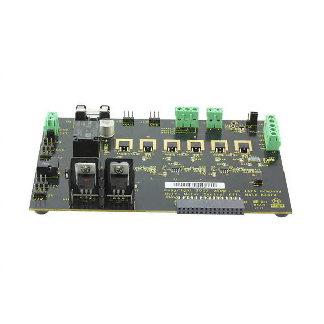


 工商网监
湘ICP备2023018690号
工商网监
湘ICP备2023018690号
