SMDJ5.0(C)A -SMDJ220(C)A
Product specification
�SMDJ5.0(C)A -SMDJ220(C)A
Features
Mechanical Data
For surface mounted applications in order to optimize
board space
Low profile package
Built-in strain relief
Glass passivated junction
Low inductance
Excellent clamping capability
3000W peak pulse power capability at 10/1000μs
waveform, repetition rate (duty cycle): 0.01%
Fast response time
Typical IR less than 1μA above 10V
High Temperature soldering: 260℃/10 seconds at
terminals
Plastic package has underwriters laboratory
flammability 94V-0
Meets MSL level 1, per J-STD-020
Safety certification:
UL
IEC61000-4-2 ESD 30KV Air, 30KV contact
compliance
Case: JEDEC DO-214AB. Molded plastic over glass
passivated junction
Terminal: Tin plated, solderable per MIL-STD-750,
Method 2026
Polarity: Color band denotes cathode except
bi-directional models
Standard Packaging: 16mm tape (EIA STD RS-481)
Weight: 0.28g
Applications
I/O interface
AC/DC power supply
Low frequency signal transmission line (RS232,
RS485, etc.)
Reference News
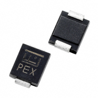
PACKAGE OUTLINE
PIN CONFIGURATION
SMC(DO-214AB) Unipolar
SMC(DO-214AB) Bipolar
Copyright© Msksemi Incorporated
www.msksemi.com
�SMDJ5.0(C)A -SMDJ220(C)A
Ratings at 25℃ ambient temperature unless otherwise specified.
Rating
Symbol
Value
Units
Peak pulse power dissipation at 10/1000μs waveform
(Note1, Note2, Fig.1)
PPPM
Minimum 3000
Watts
Peak pulse current of at 10/1000μs waveform (Note 1, Fig.3)
IPPM
See Table
Amps
PM(AV)
6.5
Watts
IFSM
300
Amps
TJ,TSTG
-55 to +150
℃
Typical thermal resistance junction to lead
RθJL
15
℃/W
Typical thermal resistance junction to ambient
RθJA
75
℃/W
Steady state power dissipation at TA=50℃ (Fig.5)
Peak forward surge current, 8.3ms single half sine-wave
superimposed on rated load, (JEDEC Method) (Note3, Fig.6)
Operating junction and Storage Temperature Range.
Notes: 1. Non-repetitive current pulse, per Fig.3 and derated above TA=25℃ per Fig.2.
2. Mounted on 8.0mm×8.0mm copper pads to each terminal.
3. 8.3ms single half sine-wave, or equivalent square wave, duty cycle=4 pulses per minutes maximum.
Electrical Characteristics (TA=25℃)
Part Number
Unidirectional Bidirectional
Device
Marking
Code
Reverse
Stand-Off
Voltage
Breakdown
Voltage
@IT
Test
Current
Maximum
Clamping
Voltage
@IPP
Peak
Pulse
Current
Revers
e
Leakag
e
@ VRWM
UNI
BI
VRWM(V)
VBR(V)
IT(mA)
VC(V)
IPP(A)
IR(μA)
SMDJ5.0A
SMDJ5.0CA
RDE
DDE
5.0
6.40~7.00
10
9.2
326.1
800
SMDJ6.0A
SMDJ6.0CA
RDG
DDG
6.0
6.67~7.37
10
10.3
291.3
800
SMDJ6.5A
SMDJ6.5CA
RDK
DDK
6.5
7.22~7.98
10
11.2
267.9
500
SMDJ7.0A
SMDJ7.0CA
PDM
DDM
7.0
7.78~8.60
10
12.0
250.0
200
SMDJ7.5A
SMDJ7.5CA
PDP
DDP
7.5
8.33~9.21
1
12.9
232.6
100
SMDJ8.0A
SMDJ8.0CA
PDR
DDR
8.0
8.89~9.83
1
13.6
220.6
50
SMDJ8.5A
SMDJ8.5CA
PDT
DDT
8.5
9.44~10.40
1
14.4
208.3
20
SMDJ9.0A
SMDJ9.0CA
PDV
DDV
9.0
10.00~11.10
1
15.4
194.8
10
SMDJ10A
SMDJ10CA
PDX
DDX
10.0
11.10~12.30
1
17.0
176.5
5
SMDJ11A
SMDJ11CA
PDZ
DDZ
11.0
12.20~13.50
1
18.2
164.8
2
SMDJ12A
SMDJ12CA
PEE
DEE
12.0
13.30~14.70
1
19.9
150.8
2
SMDJ13A
SMDJ13CA
PEG
DEG
13.0
14.40~15.90
1
21.5
139.5
2
SMDJ14A
SMDJ14CA
PEK
DEK
14.0
15.60~17.20
1
23.2
129.3
2
SMDJ15A
SMDJ15CA
PEM
DEM
15.0
16.70~18.50
1
24.4
123.0
2
SMDJ16A
SMDJ16CA
PEP
DEP
16.0
17.80~19.70
1
26.0
115.4
2
SMDJ17A
SMDJ17CA
PER
DER
17.0
18.90~20.90
1
27.6
108.7
2
SMDJ18A
SMDJ18CA
PET
DET
18.0
20.00~22.10
1
29.2
102.7
2
SMDJ20A
SMDJ20CA
PEV
DEV
20.0
22.20~24.50
1
32.4
92.6
2
SMDJ22A
SMDJ22CA
PEX
DEX
22.0
24.40~26.90
1
35.5
84.5
2
SMDJ24A
SMDJ24CA
PEZ
DEZ
24.0
26.70~29.50
1
38.9
77.1
2
Copyright© Msksemi Incorporated
www.msksemi.com
�SMDJ5.0(C)A -SMDJ220(C)A
Part Number
Unidirectional Bidirectional
Device
Marking
Code
Reverse
Stand-Off
Voltage
Breakdown
Voltage
@IT
Test
Current
Maximum
Clamping
Voltage
@IPP
Peak
Pulse
Current
Revers
e
Leakag
e
@ VRWM
UNI
BI
VRWM(V)
VBR(V)
IT(mA)
VC(V)
IPP(A)
IR(μA)
SMDJ26A
SMDJ26CA
PFE
DFE
26.0
28.90~31.90
1
42.1
71.3
2
SMDJ28A
SMDJ28CA
PFG
DFG
28.0
31.10~34.40
1
45.4
66.1
2
SMDJ30A
SMDJ30CA
PFK
DFK
30.0
33.30~36.80
1
48.4
62.0
2
SMDJ33A
SMDJ33CA
PFM
DFM
33.0
36.70~40.60
1
53.3
56.3
2
SMDJ36A
SMDJ36CA
PFP
DFP
36.0
40.00~44.20
1
58.1
51.6
2
SMDJ40A
SMDJ40CA
PFR
DFR
40.0
44.40~49.10
1
64.5
46.5
2
SMDJ43A
SMDJ43CA
PFT
DFT
43.0
47.80~52.80
1
69.4
43.2
2
SMDJ45A
SMDJ45CA
PFV
DFV
45.0
50.00~55.30
1
72.7
41.3
2
SMDJ48A
SMDJ48CA
PFX
DFX
48.0
53.30~58.90
1
77.4
38.8
2
SMDJ51A
SMDJ51CA
PFZ
DFZ
51.0
56.70~62.70
1
82.4
36.4
2
SMDJ54A
SMDJ54CA
PGE
DGE
54.0
60.00~66.30
1
87.1
34.4
2
SMDJ58A
SMDJ58CA
PGG
DGG
58.0
64.40~71.20
1
93.6
32.1
2
SMDJ60A
SMDJ60CA
PGK
DGK
60.0
66.70~73.70
1
96.8
31.0
2
SMDJ64A
SMDJ64CA
PGM
DGM
64.0
71.10~78.60
1
103.0
29.1
2
SMDJ70A
SMDJ70CA
PGP
DGP
70.0
77.80~86.00
1
113.0
26.5
2
SMDJ75A
SMDJ75CA
PGR
DGR
75.0
83.30~92.10
1
121.0
24.8
2
SMDJ78A
SMDJ78CA
PGT
DGT
78.0
86.70~95.80
1
126.0
23.8
2
SMDJ85A
SMDJ85CA
PGV
DGV
85.0
94.40~104.00
1
137.0
21.9
2
SMDJ90A
SMDJ90CA
PGX
DGX
90.0
100.00~111.00
1
146.0
20.5
2
SMDJ100A
SMDJ100CA
PGZ
DGZ
100.0
111.00~123.00
1
162.0
18.5
2
SMDJ110A
SMDJ110CA
PHE
DHE
110.0
122.00~135.00
1
177.0
16.9
2
SMDJ120A
SMDJ120CA
PHG
DHG
120.0
133.00~147.00
1
193.0
15.5
2
SMDJ130A
SMDJ130CA
PHK
DHK
130.0
144.00~159.00
1
209.0
14.4
2
SMDJ150A
SMDJ150CA
PHM
DHM
150.0
167.00~185.00
1
243.0
12.3
2
SMDJ160A
SMDJ160CA
PHP
DHP
160.0
178.00~197.00
1
259.0
11.6
2
SMDJ170A
SMDJ170CA
PHR
DHR
170.0
189.00~209.00
1
275.0
10.9
2
SMDJ180A
SMDJ180CA
HHT
IHT
180.0
201.00~222.00
1
292.0
10.3
2
SMDJ190A
SMDJ190CA
HHV
IHV
190.0
211.00~233.00
1
308.0
9.7
2
SMDJ200A
SMDJ200CA
HHX
IHX
200.0
224.00~247.00
1
324.0
9.3
2
SMDJ210A
SMDJ210CA
HHZ
IHZ
210.0
237.00~263.00
1
340.0
8.8
2
SMDJ220A
SMDJ220CA
HIE
IIE
220.0
246.00~272.00
1
356.0
8.4
2
Copyright© Msksemi Incorporated
www.msksemi.com
�SMDJ5.0(C)A -SMDJ220(C)A
Ratings and Characteristic Curves (TA=25℃ unless otherwise noted)
Figure 1. Peak Pulse Power Rating Curve
Figure 2. Pulse Derating Curve
Peak Pulse Power (P PP ) or Current (I PP )
Derating in Percentage %
PPPM - Peak Pulse Power (kW)
1000
100
10
1
0.31×0.31 ″(8.0×8.0mm)
Copper Pad Area
0.1
0.1
1
100
10
100
80
60
40
20
0
0
1000
Figure 3. Pulse Waveform
1000
Bi-directional
10
td
1
2.0
t-Time (ms)
Copyright© Msksemi Incorporated
175
100
10/1000µs Waveform
as defined by R.E.A
1.0
150
Uni-directional
Cj (pF)
IPPM - Peak Pulse Current, %I RSM
50
0
125
10000
Half Value I PPM (IPPM /2)
0
100
100000
Peak Value I PPM
100
75
Figure 4. Typical Junction Capacitance
TJ=25℃
Pulse Width(t d) is defined as
the point where the peak
current decays to 50% of I PPM
tr=10µs
50
TA-Ambient Temperature ( ℃)
td-Pulse Width (µs)
150
25
3.0
4.0
Measured at
1MHz, 100mV, 0V bias
1
10
100
VRWM -Reverse Stand-Off Voltage (V)
1000
www.msksemi.com
�SMDJ5.0(C)A -SMDJ220(C)A
Figure 5. Steady State Power Dissipation Derating
Curve
Surge Current Uni-Directional Only
IFSM - Peak Forward Surve Current (A)
PM(AV), Steady State Power Dissipation (W)
7
Figure 6. Maximum Non-Repetitive Forward
6
5
4
3
2
1
0
0
25
50
75
100
125
150
350
300
250
200
150
100
50
175
0
1
10
Number of Cycles at 60Hz
TA-Ambient Temperature ( ℃)
100
Recommended Soldering Conditions
Reflow Soldering
Critical Zone
TL to TP
tP
TP
Ramp-up
Temperature
TL
tL
TS max
TS min
Ramp-down
tS
Preheat
25
t 25℃ to Peak
Time
Copyright© Msksemi Incorporated
www.msksemi.com
�SMDJ5.0(C)A -SMDJ220(C)A
Recommended Conditions
Profile Feature
Pb-Free Assembly
Average ramp-up rate (TL to TP)
3℃/second max.
Preheat
-Temperature Min (TS min)
-Temperature Max (TS max)
-Time (min to max) (tS)
150℃
200℃
60-180 seconds
TS max to TL
-Ramp-up Rate
3℃/second max.
Time maintained above:
-Temperature (TL)
-Time (tL)
217℃
60-150 seconds
Peak Temperature (TP)
260℃
Time within 5℃ of actual Peak Temperature (tP)
20-40 seconds
Ramp-down Rate
6℃/second max.
Time 25℃ to Peak Temperature
8 minutes max.
Dimensions (SMC/DO-214AB)
Product:
Symbol
Cathode Band
D1 D
L
H1 H
d
T1
T
3.20mm
Pad:
1.75mm
4.69mm
Copyright© Msksemi Incorporated
1.75mm
Millimeters
Inches
Min.
Max.
Min.
Max.
L
6.60
7.11
0.
0.
D
5.59
6.22
2600.
2800.
D1
2.90
3.20
2200.
2450.
T
7.75
8.13
1140.
1260.
T1
0.76
1.52
3050.
3200.
d
-
0.203
030
-
0600.
H
2.20
2.80
0.087
0080.
H1
2.06
2.62
0.079
0.103
www.msksemi.com
�SMDJ5.0(C)A -SMDJ220(C)A
Attention
■ Any and all MSKSEMI Semiconductor products described or contained herein do not
handle applications that require extremely high levels of reliability, such as life-support
have specifications
that can
systems, aircraft's control systems, or
other applications whose failure can be reasonably expected to result in serious physical and/or material damage. Consult with
your MSKSEMI Semiconductor representative
nearest
you before using any MSKSEMI Semiconductor products described
or contained herein in such applications.
■ MSKSEMI Semiconductor assumes no responsibility for equipment failures that result from using products
at values that
exceed, even momentarily, rated values (such as maximum ratings, operating condition ranges, or other parameters) listed in
products specificationsof any andall MSKSEMI Semiconductor products described orcontained herein.
■ Specifications of any and all MSKSEMI Semiconductor products described or contained herein stipulate the
performance, characteristics, and functions of the described products in the independent state, and are not guarantees of the
performance, characteristics, and functions of the described products as mounted in the customer’s products or equipment. To
verify symptoms and states that cannot be evaluated in an independent device, the customer should always evaluate and test
devices mounted in the customer’sproducts orequipment.
■ MSKSEMI Semiconductor. strives to supply high-quality high-reliability products. However, any and all semiconductor
products fail with someprobability. It is possiblethat these probabilistic failures could give rise to accidents or events that could
endanger human lives, that could give rise to smoke or fire, or that could cause damage to other property. When designing
equipment, adopt safety measures so that these kinds of accidents
or events cannot occur. Such measures include but are
not limited to protective circuits anderror prevention circuitsfor safedesign, redundant design, and structural design.
■ In the event that any or all MSKSEMI Semiconductor products(including technical data, services) described
or contained
herein are controlled under any of applicable local export control laws and regulations, such products must not be exported
without obtaining the export license from theauthorities
concerned
in accordance with the above law.
■ No part of this publication may be reproduced or transmitted in any form or by any means, electronic or
mechanical, including photocopying and recording, or any information storage or retrieval system, or otherwise, without the prior
written permission of MSKSEMI Semiconductor.
■
Information (including circuit diagrams and circuit parameters) herein is for example only ; it is not guaranteed for volume
production. MSKSEMI Semiconductor believes information herein is accurate and
reliable, but no guarantees are made or
implied regarding its use or any infringementsof intellectual property rights or other rightsof third parties.
■
Any and all information described or contained herein are subject to change without notice due to
product/technology improvement, etc. Whendesigning equipment, referto the "Delivery Specification" for the MSKSEMI
Semiconductor productthat you intend to use.
Copyright© Msksemi Incorporated
www.msksemi.com
�