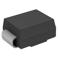
P3100SB
Thyristors Solid Protection Device
Features
For surface mounted applications to optimize board space
Low profile package
Bidirectional crowbar protection
Low leakage current : I = 5uA max
Low on-state voltage
Low Capacitance
Response Time is < 1us
YD/T 950 IEC 61000-4-5
YD/T 993 ITU K.20/21
YD/T 1082 TIA-968-A
GR 1089 Intra-building
Solid-state silicon technology
Meets MSL 1 Requirements
ROHS compliant
SMB
Schematic Diagram
Maximum Ratings and Electrical Characteristics
Symbol
Parameter
Value
Unit
IPP
Non-repetitive peak pulse current
10/1000 us
80
A
VPP
Non-repetitive peak pulse voltage
10/700us
4000
V
VESD
ESD Rating per IEC61000-4-2:
Contact
8
Air
15
KV
Ts
Storage temperature range
-40 to +150
℃
Tj
Maximum junction temperature
150
℃
Maximum ratings are those values beyond which device damage can occur. Maximum ratings applied to the device are individual stress limit
values (not normal operating conditions) and are not valid simultaneously. If these limits are exceeded, device functional operation is not
implied,damage may occur and reliability may be affected.
*Other voltages may be available upon request.
Revision B1
1
service@jy-electronics.com.cn
www.jy-electronics.com.cn
�P3100SB
Thyristors Solid Protection Device
Electrical Parameters
Symbol
VRM
Peak off-state voltage
IRM
Off-state current
VS
Switching voltage
IS
Switching current
VT
On-state voltage
IT
On-state current
IH
Holding current
CO
Off-state capacitance
Parameter
VRM
IRM
Ih
IBO
VBO
Min.
IRM=1μA
VRM
1KV/μs
VT
IT=2.2A
IH
10A,10/1000μs
IR
VRWM VBO
Typ.
Max.
2
Unit
V
5
uA
350
4
V
120
2V,1MHz
V
IBO
Ih
275
IS
Revision B1
IR
VRWM
Revision B1
TestsConditions
Vs
CO
I
Parameter
V
mA
45
pF
800
mA
service@jy-electronics.com.cn
www.jy-electronics.com.cn
�P3100SB
Thyristors Solid Protection Device
Typical electrical characterist applications
Rating and Characteristics Curves
1
Repetitive peak current
%IPP
100
Tj=25℃
C[VR]/C[VR=1V]
Tr=rise time(us)
Tp =pulse duration time (us)
F=1MHZ
0.8
VRM S=1V
0.6
0.4
50
0.2
VR(V)
0
tr
1
tp
2
5
10
20
50
100
300
Fig. 2 Relation Variation Of Junction Capacitance
Fig.1 Pulse Waveform (5/310us)
Versus Reverse Voltage Applied (Typical Values)
100
40
IT(A)
Tj=25℃
F=50HZ
Tj=25℃
ITSM(A)
30
20
10
t(s)
VT(V)
0
10
1.E-02
1.E-01
1.E+00
1.E+01
1.E+02
1.E+03
Fig.3 Non Repetitive Surge Peek On-State
Current Versus Overload Duration
2.0
IH(TJ)/IH[Tj=25℃]
1.0
Tj(℃)
0
-40
-20
0
20
40
60
80
100
120 130
1
2
3
4
5
6
7
8
Fig.4 On-State Voltage Versus On-State Current (Typical
Values)
1.08
1.07
1.06
1.05
1.04
1.03
1.02
1.01
1.00
0.99
0.98
0.97
0.96
0.95
0.94
-40
VBO[Tj]/V BO[Tj=25℃]
Tj(℃)
-20
0
20
40
60
80
100
120
130
Fig.6 Relative Variation of Break Over Voltage
Versus Junction Temperature
Fig.5 Relative Variation of Hold Current Versus
Junction Temperature
Revision B1
0
3
service@jy-electronics.com.cn
www.jy-electronics.com.cn
�P3100SB
Thyristors Solid Protection Device
Typical electrical characterist applications
Rating and Characteristics Curves
1.E+03
1.0
IR[Tj]/IR[Tj=25℃]
ZTH(j-a)/RTH(j-a)
0.9
VR=243V
0.8
0.7
1.E+02
0.6
0.5
0.4
1.E+01
0.3
0.2
Tj(℃)
1.E+00
25
50
75
Tp(s)
0.1
0
100
125
Fig.7 Relative Variation Of Leakage Current Versus
Reverse Voltage (Typical Values)
1.E-02
1.E-01
1.E+00
1.E+01
1.E+02
1.E+03
Fig.8 Variation Of Thermal Impedance Junction To
Ambient Versus Pulse Duration
SOLDERING PARAMETERS
Reflow Condition
+150℃
-Temperature Max(Ts(max))
+200℃
TP
-Time (Min to Max) (ts)
60-180 secs.
TL
3℃/sec. Max
Ts(max) to TL - Ramp-up Rate
3℃/sec. Max
-Temperature(TL)(Liquid us)
+217℃
-Temperature(tL)
60-150 secs.
Peak Temp (Tp)
+260(+0/-5)℃
Time within 5℃of actual Peak Temp (tp)
30 secs. Max
Ramp-down Rate
6℃/sec. Max
Time 25℃ to Peak Temp (TP)
8 min. Max
Do not exceed
+260℃
Revision B1
tp
Critical Zone
TL to TP
Ramp-up
tL
TS(max)
Average ramp up rate (Liquid us Temp
(TL)to peak)
Reflow
Reflow condition
-Temperature Min (Ts(min))
4
Temperature
Pre
Heat
Pb-Free assembly
Ramp-down
Preheat
TS(min)
25
ts
time to peak temperatue
(t 25℃ to peak)
Time
service@jy-electronics.com.cn
www.jy-electronics.com.cn
�P3100SB
Thyristors Solid Protection Device
Package information
SMB
SMB Mechanical Data
Case: SMB
Case Material: Molded Plastic. UL Flammability
Classification Rating 94V-0
Weight: 0.003 ounces, 0.096 gram
C
Millimeters
Inches
B
A
DIM
G
G
D
F
E
B
Min
Nom
Max
Min
Nom
Max
A
3.30
3.62
3.94
0.130
0.142
0.155
B
1.95
2.08
2.20
0.077
0.082
0.087
C
4.06
4.40
4.57
0.160
0.173
0.180
D
0.125
0.20
0.305
0.005
0.008
0.012
E
0.76
1.14
1.52
0.030
0.045
0.06
F
4.95
5.40
5.59
0.194
0.213
0.22
G
2.05
2.30
2.50
0.080
0.090
0.098
SMB
SMB Reel Dim
E
P0
K
P2
D
T
W
F
D1
A0
B0
B1
K0
P1
A0
B0
B1
D
D1
E
F
K0
T
W
P0
P1
P2
4.0
5.9
6.1
1.5
1.5
1.75
5.5
3.0
0.50
12.0
4.0
8.0
2.0
Dimension is in mm
Leader and Trailer
Direction of Feed
Tape Leader
No Components
30 components in
length
Components
Tape Trailer
(Connected To Reel Hub)
No Components
50 components in length
The LEADER is a minimum of 30 components in length and it consists of empty cavities with sealed cover tape
The TRAILER is a minimum of 50 components in length and it consists of empty cavities with sealed cover tape.
Revision B1
5
service@jy-electronics.com.cn
www.jy-electronics.com.cn
�P3100SB
Thyristors Solid Protection Device
Marking Codes
P3100
P3100
OR
XXXYY
XXXYY
Note:
(1) "P3100" is part number,fixed.
(2) "XXX" is the last 3 characters of the wafer's Lot No.,
"YY" is internal code.
Ordering Information
Device
Qty per Reel
Reel Size
P3100SB
3000
13 Inch
Revision B1
6
service@jy-electronics.com.cn
www.jy-electronics.com.cn
�
很抱歉,暂时无法提供与“P3100SB”相匹配的价格&库存,您可以联系我们找货
免费人工找货