WM30
Power analyzer for three-phase systems
Benefits
Description
WM30 is a modular power analyzer for single-,
two- and three-phase systems.
It is made up of a maximum of four components:
the main unit that displays measurements on the
LCD display and manages 4 alarms, and three
accessory modules, one with digital outputs, one
with analogue outputs and the other for
communication.
The digital output module associates alarms with
static or relay outputs and/or transmits pulses
proportional to energy consumption.
The analogue output module associates 0-20 mA
or 0-10 V outputs to measured variables.
The communication module allows you configure
the analyzer and transmit data using a different
communication protocol according to the version.
• Clarity. The wide backlit LCD display clearly shows the
measurements and the configuration parameter values.
• Simplicity. An optical port is available for quick analyzer
configuration using OptoProg (CARLO GAVAZZI).
• Specific software. WM30 can be configured and
measurements viewed from UCS configuration software
(CARLO GAVAZZI). The software and subsequent
updates are free.
• Scalability. Three accessory modules can be added to
WM30 according to need. This way, the analyzer
extends its control capacities and communicates data
remotely.
• Communication flexibility. The communication
module is available in Modbus RTU, Modbus TCP/IP,
BACnet IP, BACnet MS/TP and Profibus DP V0
versions.
• Fast installation. WM30 and accessory modules are all
equipped with detachable terminals. Modules can be
quickly installed via the specifically designed fast
coupling pins.
• Tamper-proof. WM30 configuration access can be
locked. Terminals and accessory modules can be
sealed.
Main functions
•
•
•
•
•
•
•
Measure main electrical variables and voltage and current harmonic distortions
Measure active and reactive energy
Measure load operating hours
Manage up to 4 alarms
Manage two digital outputs (via optional accessory module)
Manage two analogue outputs (via optional accessory module)
Transmit data to other systems (via optional accessory module)
28/04/2022 WM30 DS ENG
CARLO GAVAZZI Controls SpA
1
�WM30
Applications
WM30 can be installed in any switchboard to control energy consumption, main electrical variables and
harmonic distortion.
In automation, WM30can use the communication module with Profibus protocol to both communicate data on
consumption to supervision systems and manage them independently if installed on a machine.
In building, WM30can be installed in existent architectures using the communication module with BACnet
protocol (on RS485 or Ethernet).
Components
Module
Description
WM30
Main unit, measures and displays main electrical variables. With LCD display and touch
keypad, it lets you set measurement parameters, configure accessory modules and manage up to 4 alarms.
Digital outputs (optional)
Accessory module with two digital outputs. Expands main unit capacity, specifically allowing you to:
transmit pulses proportional to energy consumption
control digital outputs (static or relay according to the module)
Analogue outputs (optional)
Accessory module with two analogue outputs. Expands main unit capacity, specifically
allowing you to associate a 0-20mA or 0-10V output to a measured variable
Communication (optional)
Accessory module that lets you transmit data to other systems or configure the analyzer
from remote
Compatible accessory modules
Type
Digital outputs
Analogue outputs
Communication
28/04/2022 WM30 DS ENG
Module description
Code
Double static output
M O O2
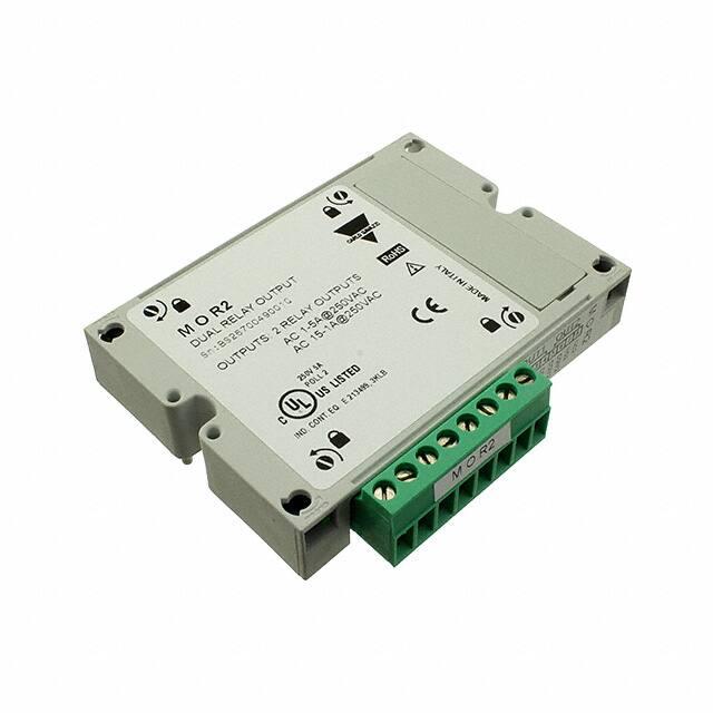
Double relay output
M O R2
Double analogue output (+20mA dc)
M O A2
Double analogue output (+10V dc)
M O V2
Modbus RTU communication on RS485/RS232
M C 485232
Modbus TCP/IP communication on Ethernet
M C ETH
BACnet IP communication on Ethernet
M C BAC IP
BACnet MS/TP communication on RS485
M C BAC MS
Profibus DP V0 communication on RS485
M C PB
CARLO GAVAZZI Controls SpA
2
�WM30
Possible configurations
WM30only
WM30+ 1 module
WM30+ 2 modules
WM30+ 3 modules
NOTICE: maximum 1 module per type. In the configuration with 2 or 3 modules, the communication module is
installed last.
28/04/2022 WM30 DS ENG
CARLO GAVAZZI Controls SpA
3
�WM30
Features
General features
Material
Front: ABS, self-extinguishing V-0 (UL 94)
Back and accessory modules: PA66, self-extinguishing V-0 (UL 94)
Protection degree
Front: IP65 NEMA 4x NEMA 12
Terminals: IP20
Type: detachable
Section: 2.5 mm2 maximum
Terminals
Torque: 0.5 Nm
Overvoltage category
Cat. III
Pollution degree
2
Noise rejection (CMRR) 100 dB, from 42 to 62 Hz
Double electrical insulation on areas accessible to the user.
For insulation between inputs and outputs, see "Input and output insulation" below.
Insulation
Input and output insulation
Note: test conditions: 4 kV rms ac for one minute.
Type
Power supply (H or Measurement inputs
L)
[kV]
[kV]
Digital outputs
[kV]
Serial
port
[kV]
Ethernet port
[kV]
Power supply (H or L)
-
4
4
4
4
Measurement inputs
4
-
4
4
4
Digital outputs
4
4
-
4
4
Serial port
4
4
4
-
NP
Ethernet port
4
4
4
NP
-
Key
• NP: combination not possible
• 4: 4 kV rms insulation (EN 61010-1, IEC 60664-1, overvoltage category III, pollution degree 2, double
insulation on system with maximum 300 V rms to ground)
Environmental specifications
Operating temperature
From -25 to +55 °C/from -13 to +131 °F
Storage temperature
From -30 to +70 °C/from -22 to 158 °F
Note: R.H. < 90 % non-condensing @ 40 °C / 104 °F.
28/04/2022 WM30 DS ENG
CARLO GAVAZZI Controls SpA
4
�WM30
Conformity
Directives
2014/35/EU (LVT - Low Voltage)
2014/30/EU (Electromagnetic Compatibility)
2011/65/EU, 2015/863/EU (Electric-electronic equipment hazardous substances)
Standards
Electromagnetic compatibility (EMC) - emissions and immunity: EN61000-6-3,
EN61000-6-2
Electrical safety: EN 61010-1
Metrology: EN62053-22, EN62053-23
Pulse output: IEC 62053-31, DIN 43864
Approvals
28/04/2022 WM30 DS ENG
CARLO GAVAZZI Controls SpA
5
�Main unit
Main features
Description
Main unit with LCD display and touch keypad to
view measurements, configure the system and
manage 4 alarms.
It can be integrated by digital output, analogue
output and communication modules.
Four versions are available (AV4, AV5, AV6 and
AV7) to manage different current and voltage
inputs.
It can be quickly configured with OptoProg via
optical port.
28/04/2022 WM30 DS ENG
• System and phase variables (4 x 3 digits): V L-L, V L-N,
A, W/var/VA, PF, Hz
• Active and reactive imported and exported energy
meters (10 digits)
• Calculate the average and maximum system and phase
values of all the electrical variables
• Calculate current and voltage THD (total harmonic
distortions) up to the 32nd harmonic
• Calculate load operating hours
• Auxiliary power supply
• 4 virtual alarms
• Backlit LCD display and touch keypad
• Optical port
• Detachable terminals
• Sealable terminal caps
• Configuration via keypad or UCS configuration software
(desktop or mobile Android App)
• Filter to stabilize displayed measurements
Main functions
• Measure main electrical variables and harmonic voltage
and current distortions
• Measure active and reactive energy
• Measure load operating hours
• Manage up to 4 alarms
CARLO GAVAZZI Controls SpA
6
�Main unit
Structure
Fig. 1 Front
Element
Description
A
Optical port and plastic support for OptoProg (CARLO GAVAZZI) connection
B
Backlit LCD display
C
LED that blinks with frequency proportional to active energy consumption, see "LED"
on page 14
D
Touch keypad
28/04/2022 WM30 DS ENG
CARLO GAVAZZI Controls SpA
7
�Main unit
A
C
D
E
F
B
Fig. 2 Back
Element
Description
A
Detachable power supply terminals
B
Detachable current input terminals
C
Detachable voltage input terminals
D
Rotary selector to lock configuration
E
Local bus port for accessory modules
F
Power supply status LED, see "LED" on page 14
28/04/2022 WM30 DS ENG
CARLO GAVAZZI Controls SpA
8
�Main unit
Features
Panel mounting
Weight
420 g (packaging included)
96
89,97
Assembly
96
22,2
93
General features
27,9
Electrical specifications
Electrical system
Single-phase (2-wire)
Managed electrical sys- Two-phase (3-wire)
tem
Three-phase with neutral (4-wire)
Three-phase without neutral (3-wire)
Voltage inputs
Inputs
AV4
AV5
Voltage connection
28/04/2022 WM30 DS ENG
AV7
Direct or via VT/PT
VT/PT transformation
ratio
Rated voltage L-N
(from Un min to Un
max)
AV6
From 1 to 9999
From 220 to 400 V
From 57.7 to 133 V
CARLO GAVAZZI Controls SpA
9
�Main unit
Voltage inputs
Rated voltage L-L (from
Un min to Un max)
From 380 to 690 V*
From 100 to 230 V
Voltage tolerance
-20%, + 15%
Continuous: 1.2 Un max
For 500 ms: 2 Un max
Overload
Input impedance
>1.6 MΩ
Frequency
From 40 to 440 Hz
Note: *for UL applications max 600 VL-L, 40 °C (104 °F)
Current inputs
Inputs
AV4
AV5
AV6
Current connection
Via CT
CT transformation ratio
Rated current (In)
Minimum current (lmin)
Maximum current
(lmax)
Start-up current (lst)
AV7
From 1 to 9999
1A
5A
1A
0.01 A
0.05 A
0.01 A
2A
6A
2A
1 mA
5 mA
1 mA
Continuous: Imax
For 500 ms: 20 Imax
Overload
Input impedance
< 0.2 VA
Maximum CTxVT ratio
9999 x 9999
Power supply
Power supply
H
L
From 100 to 240 V ac/dc ± 10%
From 24 to 48 V ac/dc ± 15%
Consumption
10 W, 20 VA
Measurements
Method
TRMS measurements of distorted waveforms
Sampling
3200 samples/s @50 Hz
3840 samples/s @60 Hz
28/04/2022 WM30 DS ENG
CARLO GAVAZZI Controls SpA
10
�Main unit
Available measurements
Active energy
Unit
System
Phase
Imported (+) Total
kWh+
●
-
Imported (+) partial
kWh+
●
-
Exported (+) Total
kWh-
●
-
Exported (+) partial
kWh-
●
-
Reactive energy
Unit
System
Phase
Imported (+) Total
kvarh+
●
-
Imported (+) partial
kvarh+
●
-
Exported (+) Total
kvarh-
●
-
Exported (+) partial
kvarh-
●
-
Electrical variable
Unit
System
Phase
A
●
●
DMD
A
●
●
MAX
A
●
●
A
●
-
DMD
A
●
-
MAX
A
●
-
V
●
●
DMD
V
●
●
MAX
V
●
●
Current
Neutral current
Voltage L-N
Voltage L-L
V
●
●
DMD
V
●
●
MAX
V
●
●
Asymmetry VLL
%
●
-
Asymmetry VLN
%
●
-
Active power
kW
●
●
DMD
kW
●
●
MAX
kW
●
●
Apparent power
kVA
●
●
DMD
kVA
●
●
MAX
kVA
●
●
kvar
●
●
DMD
kvar
●
●
MAX
kvar
●
●
Power factor
PF
●
●
DMD
PF
●
●
Reactive power
28/04/2022 WM30 DS ENG
CARLO GAVAZZI Controls SpA
11
�Main unit
Electrical variable
Unit
System
Phase
PF
●
●
Hz
●
-
DMD
Hz
●
-
MAX
Hz
●
-
THD Current*
THD A %
-
●
DMD
THD A %
-
●
MAX
THD A %
-
●
MAX
Frequency
THD Voltage L-N*
THD L-N %
-
●
DMD
THD L-N %
-
●
MAX
THD L-N %
-
●
THD L-L %
-
●
DMD
THD L-L %
-
●
MAX
THD L-L %
-
●
h
●
-
THD Voltage L-L*
Run hour meter
* Up to 32nd harmonic
Note: the available variables depend on the type of system set.
Measurement mode
Depending on the APPLICATION setting, a different selection of variables is available on the display. The
energy calculation is not affected and works always as bidirectional.
Energy metering
For every measuring interval time, the energies of the single phases are summed; according to the sign of the
result, the positive (kWh+) or negative totalizer (kWh-) is increased.
Example:
P L1= +2 kW, P L2= +2 kW, P L3= -3 kW
Integration time = 1 hour
+kWh=(+2+2-3)x1h=(+1)x1h=1 kWh
-kWh=0 kWh
Measurement accuracy
Current
From 0.05 In to Imax
±(0.2% rdg + 2dgt)
From 0.01 In to 0.05 In
±(0.5% rdg + 2dgt)
28/04/2022 WM30 DS ENG
CARLO GAVAZZI Controls SpA
12
�Main unit
Phase-phase voltage
From Un min -20% to
Un max +15%
±(0.2% rdg +1dgt)
Phase-neutral voltage
From Un min -20% to
Un max +15%
±(0.5% rdg +1dgt)
Active and apparent power
From 0.05 In to Imax
(PF=0.5L, 1, 0.8C)
±(0.5% rdg +1dgt)
From 0.01 In to 0.05 In
(PF=1)
±(1% rdg +1dgt)
Reactive power
From 0.1 In to Imax
(sinϕ=0.5L, 0.5C)
From 0.05 In to Imax
(sinϕ=1)
±(1% rdg + 1 dgt)
From 0.05 In to 0.1 In
(sinϕ=0.5L, 0.5C)
From 0.02 In to 0.05 In
(PF=1)
±(1.5% rdg + 1 dgt)
Power factor
±[0.001+0.5%(1 – PF rdg)]
Active energy
Class 0.5S (EN62053-22), class 0.5 (ANSI C12.20)
Reactive energy
Class 2 (EN62053-23, ANSI C12.1)
THD
±1%
Frequency
From 45 to 65 Hz
±(0.02% rdg + 1 dgt)
From 65 to 340 Hz
±(0.05% rdg + 1 dgt)
From 340 to 440 Hz
±(0.1% rdg + 1 dgt)
Display
Type
Backlit LCD
Refresh time
250 ms
Description
5 rows:
• 1st: 10 digits (6 mm)
• 2nd, 3rd, 4th, 5th: 4 digits (9.5 mm)
Variable readout
Instantaneous: 4 digits, min: 0.001, max: 9 999
Energy: 10 digits, min: 0.01, max: 9 999 999 999
28/04/2022 WM30 DS ENG
CARLO GAVAZZI Controls SpA
13
�Main unit
LED
Red (kWh). Weight: proportional to energy consumption and depending on the CT and VT/ PT
ratio product (16 Hz maximum frequency):
Front
Weight (kWh per pulse)
CT*VT/PT
0.001
≤7
0.01
From 7.1 to 70
0.1
From 70.1 to 700
1
From 700.1 to 7000
10
From 7001 to 70 k
100
> 70.01 k
Red (AL1, AL2, AL3, AL4). Alarm status.
Back
Green. Power supply status.
Special functions
•
•
•
•
•
•
•
4 virtual alarms (up, down, in or out alarm)
Filter to stabilize variable measurements with high fluctuations
Load operating hour meter
Clock
Total active and reactive energy meters and average, minimum, max dmd and maximum values reset
Optical port for configuration via OptoProg
Password protected settings menu
28/04/2022 WM30 DS ENG
CARLO GAVAZZI Controls SpA
14
�Main unit
Connection Diagrams
Fig. 3 Three-phase system with
neutral (4-wire, 3P.n),
unbalanced load and 3 CT. 315
mA fuse (F).
Fig. 4 Three-phase system with
neutral (4-wire, 3P.n), unbalanced
load, 3 CT and 3 VT/PT.
Fig. 5 Three-phase system with
neutral (4-wire, 3P.2), balanced
load, 1 CT. 315 mA fuse (F).
Fig. 6 Three-phase system with
neutral (4-wire, 3P.2), balanced
load, 1 CT and 1 VT/PT.
Fig. 7 Three-phase system without
neutral (3-wire, 3P), unbalanced load
and 3 CT. 315 mA fuse (F).
Fig. 8 Three-phase system
without neutral (3-wire, 3P),
unbalanced load, 3 CT and 2
VT/PT.
Fig. 9 Three-phase system
without neutral (3-wire, 3P)
unbalanced load and 2 CT
(Aron). 315 mA fuse (F).
Fig. 10 Three-phase system without
neutral (3-wire, 3P), unbalanced load,
2 CT (Aron) and 2 VT/PT.
Fig. 11 Three-phase system
without neutral (3-wire, 3P.1),
balanced load, 1 CT.
28/04/2022 WM30 DS ENG
CARLO GAVAZZI Controls SpA
15
�Main unit
Fig. 12 Three-phase system
without neutral (3-wire, 3P.1),
balanced load, 1 CT and 2
VT/PT.
Fig. 15 Single-phase system (2wire, 1P), 1 CT. 315 mA fuse (F).
28/04/2022 WM30 DS ENG
Fig. 13 Two-phase system (3-wire,
2P), 2 CT. 315 mA fuse (F).
Fig. 14 Two-phase system (3wire, 2P), 2 CT and 2 VT/PT.
Fig. 16 Single-phase system (2-wire,
1P), 1 CT and 1 VT/PT.
Fig. 17 Auxiliary power
supply (H). 250 V [T] 630
mA fuse (F).
Auxiliary power supply
(L). 250 V [T] 3.15 A fuse
(F).
CARLO GAVAZZI Controls SpA
16
�Main unit
References
WM30 AV
3
(9 characters total)
Enter the code option instead of
Code
Options
W
-
-
M
-
-
3
-
-
0
-
-
A
-
-
V
-
-
4
From 380 to 690 V L-L ac, 1(2) A, connection via CT
5
From 380 to 690 V L-L ac, 5(6) A, connection via CT
6
From 100 to 230 V L-L ac, 5(6) A, connection via CT
7
From 100 to 230 V L-L ac, 1(2) A, connection via CT
-
-
H
auxiliary power supply from 100 to 240 V ac/dc
L
auxiliary power supply from 24 to 48 V ac/dc
3
Description
Further reading
Information
Document
Where to find it
Instruction manual
Instruction manual - WM30
www.productselection.net
28/04/2022 WM30 DS ENG
CARLO GAVAZZI Controls SpA
17
�Main unit
CARLO GAVAZZI compatible components
Purpose
Current measurement
accessories
Component name/code
Notes
CTD1X, CTD2X,
CTD3X, CTD4X
Solid core current transformers (1 or 5 A secondary current, 40 to
1600 A primary current) for cable or bus bar. See relevant datasheets.
CTD1Z
Solid core current transformers (5 A secondary current, 50 to 200 A
primary current) for cable or bus bar. See relevant datasheets.
CTA5, CTA6
Split core current transformers for retrofit applications (5 A secondary current, 100 to 600 A primary current) for cable or bus bar.
See relevant datasheets.
CTD5S, CTD6S,
CTD8S, CTD9S,
CTD10S
Split core current transformers (1 or 5 A secondary current, 100 to
3200 A primary current) for bus bar. See relevant datasheets.
CTD8V, CTD8V,
CTD9V, CTD9H,
CTD10V, CTD10H
Solid core current transformers (1 or 5 A secondary current, 150 to
3200 A primary current) for bus bar. See relevant datasheets.
CTD8Q
Solid core current transformers (5 A secondary current, 1000 to
4000 A primary current) for bus bar. See relevant datasheets.
Manage two digital outputs/associate alarms to
digital outputs
M O O2
M O R2
See "Digital output modules" on page 19
Manage two analogue outputs
M O A2
M O V2
See "Analogue output modules" on page 25
Transmit data remotely
M C 485232
M C ETH
M C BAC IP
M C BAC
M C PB
See
Configure analyzer via
desktop application
UCS configuration software
Available for free download at: www.productselection.net
Configure analyzer via
Mobile Android App
UCS Mobile Android
App
Available for free download at: Google Play Store
Monitor data from several
analyzers
UWP3.0
See relevant datasheet
Quickly configure several
analyzers via optical interface
OptoProg
See relevant datasheet
RS485/USB conversion
SIU-PC3
See relevant datasheet
28/04/2022 WM30 DS ENG
CARLO GAVAZZI Controls SpA
18
�Digital output modules
Main features
• Two digital outputs (static or relay)
• Three possible functions for each output
• Configuration via main unit keypad or UCS configuration
software
• Easy mountingon main unit
• Detachable terminals
• Local bus connection to main unit
Main functions
Description
• Manage two static or relay outputs
• Associate static or relay outputs with alarms
• Transmit pulses proportional to energy consumption
Accessory module for WM analyzer family that
associates static or relay outputs to alarms and/or
transmits pulses proportional to energy
consumption.
Each output can run three different functions:
alarm, remote control or pulse.
28/04/2022 WM30 DS ENG
CARLO GAVAZZI Controls SpA
19
�Digital output modules
Structure
C
A
A
D
A
B
A
Fig. 18 Front
Element
Description
A
Main unit fastening pins
B
Detachable digital output terminals
C
Local bus port for main unit
D
Local bus port for communication module
Digital output functions
Digital outputs can run three different functions:
• Alarm: output associated with an alarm and directly managed by WM30
• Remote control: output status managed via communication
• Pulse: pulse transmission output on active or reactive, imported or exported energy consumption.
28/04/2022 WM30 DS ENG
CARLO GAVAZZI Controls SpA
20
�Digital output modules
Features
General
On main unit
Weight
80g
Power supply
Self power supply via local bus
62,99
Mounting
89,49
16
Static output module (M O O2)
Maximum number of
outputs
2
Type
Opto-mosfet
Features
VON: 2.5 V dc, 100 mA max
VOFF: 42 V dc max
Configuration parameters
Output function: alarm/remote control/pulse
Associated output alarm and normal status ("alarm" function only)
Pulse weight, transmitted energy type, test transmission settings ("pulse" function only)
Configuration mode
Via keypad or UCS software
Relay output module (M O R2)
Maximum number of
outputs
2
Type
SPDT relay
28/04/2022 WM30 DS ENG
CARLO GAVAZZI Controls SpA
21
�Digital output modules
Features
AC1: 5 A @ 250 V ac
AC15: 1 A @250 V ac
Configuration parameters
Output function: alarm/remote control/pulse
Associated output alarm and normal status ("alarm" function only)
Pulse weight, transmitted energy type, test transmission settings ("pulse" function only)
Configuration mode
Via keypad or UCS software
28/04/2022 WM30 DS ENG
CARLO GAVAZZI Controls SpA
22
�Digital output modules
Connection Diagrams
1
2
3
4
5
6
3
4
5
6
7
8
7
Fig. 19 M O O2. Double static opto-mosfet output.
28/04/2022 WM30 DS ENG
2
Fig. 20 M O R2. Double relay output.
CARLO GAVAZZI Controls SpA
23
�Digital output modules
References
Order code
Code
Description
M O O2
Double static output
M O R2
Double relay output
Further reading
Information
Document
Where to find it
Instruction manual - WM30
Instruction manual - WM30
www.productselection.net
Digital output module instruction
manual
CARLO GAVAZZI compatible components
Purpose
Power the module via
analyzer
28/04/2022 WM30 DS ENG
Component name/code
WM20
WM30
WM40
Notes
The digital output module only works connected to an analyzer. See relevant datasheets.
CARLO GAVAZZI Controls SpA
24
�Analogue output modules
Main features
• Two analogue outputs (0 to 20 mA or 0 to 10V)
• Configuration via main unit keypad or UCS configuration
software
• Easy mounting on main unit
• Detachable terminals
• Local bus connection to main unit
Main functions
• Associate electrical variables to analogue outputs.
Description
Accessory module for WM analyzer family that
associates analogue outputs to electrical
variables.
Depending on the versione the output range can
be set between 0 and 20 mA or 0 and 10 V dc.
28/04/2022 WM30 DS ENG
CARLO GAVAZZI Controls SpA
25
�Analogue output modules
Structure
Fig. 21 Front
Element
Description
A
Main unit fastening pins
B
Local bus port for main unit
C
Analogue outputs
D
Local bus port for communication module
Analogue output functions
Analogue outputs can be linked to any electrical variables.
28/04/2022 WM30 DS ENG
CARLO GAVAZZI Controls SpA
26
�Analogue output modules
Features
General
On main unit
Weight
80g
Power supply
Self power supply via local bus
62,99
Mounting
89,49
16
Analogue output module 0-20mA (M O A2)
Maximum number of
outputs
2
Type
0 to 20 mA dc
Accuracy
0.2% FS
Features
Response time ≤ 400 ms typical (filter excluded)
Ripple ≤1% (according to IEC 60688-1, EN 60688-1)
Total temperature drift ≤500 ppm/°C
Load ≤600Ω
Configuration parameters
Associated electrical variable.
Min analogue output (as a percentage of 20mA)
Max analogue output (as a percentage of 20mA)
Electrical variable value corresponding to min output.
Electrical variable value corresponding to max output.
Configuration mode
Via keypad or UCS software
28/04/2022 WM30 DS ENG
CARLO GAVAZZI Controls SpA
27
�Analogue output modules
Analogue output module 0-10V (M O V2)
Maximum number of
outputs
2
Type
0 to 10 V dc
Accuracy
0.2% FS
Features
Response time ≤ 400 ms typical (filter excluded)
Ripple ≤1% (according to IEC 60688-1, EN 60688-1)
Total temperature drift ≤350 ppm/°C
Load ≥10kΩ
Configuration parameters
Associated electrical variable.
Min analogue output (as a percentage of 10 V)
Max analogue output (as a percentage of 10 V)
Electrical variable value corresponding to min output.
Electrical variable value corresponding to max output.
Configuration mode
Via keypad or UCS software
28/04/2022 WM30 DS ENG
CARLO GAVAZZI Controls SpA
28
�Analogue output modules
Connection Diagrams
Out1
1
2
Out2
3
4
Fig. 22 M O A2. Double analogue output 0-20mA.
28/04/2022 WM30 DS ENG
Out1
1
2
Out2
3
4
Fig. 23 M O V2. Double analogue
output 0-10V.
CARLO GAVAZZI Controls SpA
29
�Analogue output modules
References
Order code
Code
Module description
M O A2
Double analogue output 0-20mA.
M O V2
Double analogue output 0-10V.
Further reading
Information
Document
Where to find it
WM30 instruction manual
Instruction manual - WM30
www.productselection.net
Analogue output module instruction
manual
CARLO GAVAZZI compatible components
Purpose
Power the module via
analyzer
28/04/2022 WM30 DS ENG
Component name/code
WM20
WM30
WM40
Notes
The digital output module only works connected to an analyzer. See relevant datasheets.
CARLO GAVAZZI Controls SpA
30
�Communication modules
Main features
• Supported communication protocols: Modbus, BACnet,
Profibus. See "Communication module overview " on
page 21
• Configuration via main unit keypad or UCS configuration
software
• Easy mounting on main unit
• Local bus connection to main unit
Main functions
• Transmit data remotely
• Configure the system
Description
Accessory module for WM analyzer family
connected to the main unit that transmits system
data remotely using a different communication
protocol according to the version.
Communication module overview
Module code
M C 485232
M C ETH
M C BAC IP
M C BAC MS
M C PB
28/04/2022 WM30 DS ENG
Communication protocols
Port
Modbus RTU
RS485, RS232
Modbus TCP/IP
Ethernet
BACnet IP, Modbus TCP/IP
Ethernet
BACnet MS/TP
RS485
Modbus TCP/IP
Ethernet
Profibus DP V0 slave
RS485
Modbus RTU
micro USB
CARLO GAVAZZI Controls SpA
31
�Communication modules
Structure
A
D
B
B
A
C
B
B
A
Fig. 24 Front
Note: NOTE: the image refers to the M C BAC MS module.
Area
A
Description
Communication port area
Note: the communication ports depend on the communication module, see "Communication module overview" on the previous page
B
Main unit fastening pins
C
Communication status LED (M C 485232, M C BAC MS, M C PB)
D
Local bus port for main unit or digital output module
28/04/2022 WM30 DS ENG
CARLO GAVAZZI Controls SpA
32
�Communication modules
Features
General
Mounting
On main unit (with or without digital output module)
Power supply
Self power supply via local bus
Weight
80g
M C 485232 module
RS485 port
Protocols
Modbus RTU
Devices on the same
bus
Max 160 (1/5 unit load)
Communication type
Multidrop, bidirectional
Connection type
2 wires, maximum distance 1000 m
Configuration parameters
Modbus address (from 1 to 247)
Baud rate (9,6/ 19,2/ 38,4/ 115,2 kbps)
Parity (None/ Odd/ Even)
Configuration mode
Via keypad or UCS software
RS232 port
Protocols
Modbus RTU
Communication type
Bidirectional
Connection type
3 wires, maximum distance 15 m
28/04/2022 WM30 DS ENG
CARLO GAVAZZI Controls SpA
33
�Communication modules
Configuration parameters
Modbus address (from 1 to 247)
Baud rate (9,6/ 19,2/ 38,4/ 115,2 kbps)
Parity (None/ Odd/ Even)
Configuration mode
Via keypad or UCS software
Note: the RS485 and RS232 ports are alternative.
LED
Meaning
Communication status:
Yellow: receiving
Green: transmitting
M C ETH module
Ethernet port
Protocols
Modbus TCP/IP
Client connections
Maximum 5 simultaneously
Connection type
RJ45 connector (10 Base-T, 100 Base-TX), maximum distance 100 m
Configuration parameters
IP address
Subnet mask
Gateway
TCP/IP port
Configuration mode
Via keypad or UCS software
M C BAC IP module
Ethernet port
Protocols
BACnet IP (reading) Modbus
TCP/IP (reading and configuration)
Client connections
(Modbus only) Maximum 5 simultaneously
Connection type
RJ45 connector (10 Base-T, 100 Base-TX), maximum distance 100 m
BACnet IP protocol:
Configuration parameters
•
•
•
•
•
Instance number (from 0 to 9999 via keypad, from 0 to 4194302 via communication)
Foreign Device enabling
BBMD address
UDP port
WM30 time-to-live recording as Foreign Device on specified BBMD server
Modbus TCP/IP protocol:
•
•
•
•
28/04/2022 WM30 DS ENG
IP address
Subnet mask
Gateway
TCP/IP port
CARLO GAVAZZI Controls SpA
34
�Communication modules
Ethernet port
Supported services
"I-have", "I-am", "Who-has", "Who-is", "Read-property (multiple)"
Supported objects
Type 2 (analogue value including COV property), type 5 (binary value, for alarm transmission),
type 8 (device)
Configuration mode
Via keypad or UCS software
M C BAC MS module
RS485 port
Protocols
BACnet MS/TP (measurement reading and object description writing)
Communication type
Multidrop, monodirectional
Connection type
2 wires, maximum distance 1000 m
Supported services
"I-have", "I-am", "Who-has", "Who-is", "Read-property (multiple)"
Supported objects
Type 2 (analogue value including COV property), type 5 (binary value, for alarm transmission),
type 8 (device)
BACnet IP protocol:
Configuration parameters
• Instance number (from 0 to 9999 via keypad, from 0 to 4194302 via communication)
• Baud rate (9,6/ 19,2/ 38,4/ 57,6/ 76,8 kbps)
• MAC address (from 0 to 127)
Configuration mode
Via keypad or UCS software
Ethernet port
Protocols
Modbus TCP/IP (configuration)
Client connections
(Modbus only) Maximum 5 simultaneously
Connection type
RJ45 connector (10 Base-T, 100 Base-TX), maximum distance 100 m
Configuration parameters
IP address
Subnet mask
Gateway
TCP/IP por
Configuration mode
Via keypad or UCS software
LED
Meaning
Communication status:
Yellow: receiving
Green: transmitting
M C PB module
Profibus port
Protocols
Profibus DP V0 slave
Connection type
9-pin D-sub receptacle RS485
28/04/2022 WM30 DS ENG
CARLO GAVAZZI Controls SpA
35
�Communication modules
Configuration parameters
Address, via keypad
Other settings with UCS software via serial communication
Configuration mode
Via keypad or UCS software
Micro-USB port
Protocols
Modbus RTU
Type
USB 2.0 (USB 3.0 compatible)
Connection type
Micro-USB B
Baud rate
Any (maximum 115.2 kbps)
Address
1
LED
Meaning
28/04/2022 WM30 DS ENG
Communication status:
Red: between module and main unit
Green: between module and Profibus master
CARLO GAVAZZI Controls SpA
36
�Communication modules
Connection Diagrams
8
8
7
7
6
6
4
4
3
3
2
1
2
1
Fig. 25 M C 485232. RS485 serial port.
Note: additional meters with RS485 are connected in daisy chain. The serial output must only be terminated on
the last network meter connecting terminals B+ and T.
8
7
6
4
3
2
1
Fig. 26 M C 485232. RS232 serial port.
4
4
3
3
2
1
2
1
Fig. 27 M C BAC MS. RS485 serial port.
Note: additional meters with RS485 are connected in daisy chain. The serial output must only be terminated on
the last network meter connecting terminals B+ and T.
28/04/2022 WM30 DS ENG
CARLO GAVAZZI Controls SpA
37
�Communication modules
References
Order code
Code
MC 485232
MC ETH
Module description
Modbus RTU communication on RS485/RS232
Modbus TCP/IP communication on Ethernet
MC BAC IP
BACnet IP communication on Ethernet
MC BAC MS
BACnet MS/TP communication on RS485
MC PB
Profibus DP V0 communication on RS485
Further reading
Information
Document
Where to find it
WM30 instruction manual
Instruction manual - WM30
www.productselection.net
Communication module instruction
manual (M C 485232, M C ETH, M C
BAC IP, M C BAC MS)
Communication module instruction
manual (M C PB)
CARLO GAVAZZI compatible components
Purpose
Power the module via
analyzer
Component name/code
WM20
WM30
WM40
Notes
The communication module only works connected to an analyzer. See relevant datasheets.
COPYRIGHT ©2022
Content subject to change. Download the PDF: www.gavazziautomation.com
28/04/2022 WM30 DS ENG
CARLO GAVAZZI Controls SpA
38
�


 工商网监
湘ICP备2023018690号
工商网监
湘ICP备2023018690号