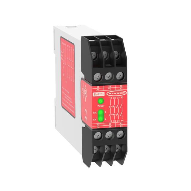
EM-F-7G Safety Extension Module
Datasheet
One-Channel Control with Four Safety Output Channels
•
•
•
•
•
•
•
Safety Extension Module provides additional safety outputs for a Primary Safety
Device (for example, an E-stop safety module or a two-hand control module)
One-channel control
Features four 6-amp switching channels for connection to control-reliable
machine power interrupt circuits
Contact status outputs are provided for connection to the Primary Safety Device’s
monitoring input
24 V ac/dc operation
Housed in a narrow, 22.5 mm (0.9 in) DIN-rail-mountable module
Design complies with standards UL 991 and EN 60204
Overview
The EM-F-7G Safety Extension Module provides additional forced-guided (positive-guided) relay contacts for a Primary Safety Device,
such as an E-stop Safety module or a two-hand control module. Controlled by a safety output of the Primary Safety Device, the EM-F-7G
Module provides four safety outputs.
These outputs may be connected to control-reliable machine power interrupt circuits. Each of the four Extension Module safety outputs
is a series connection of two forced-guided relay contacts.
The safety outputs of the Safety Extension Module follow the action of the safety output from the Primary Safety Device which controls
it, within a switching delay time of approximately 20 milliseconds. The Extension Module’s four safety outputs are each rated for up to
250 V ac/dc at up to 6 A.
Input Power
ON
13
A1
33
Y2
EM-F-7G
13
K1 Energized
K2 Energized
23
Y1
23
33 43
Power
CH.
1
CH.
2
43
14
The Safety Extension Module offers an output circuit at terminals Y1 and Y2
which provides K1 and K2 contact status information for connection to the
monitoring input of the Primary Safety Device. This monitoring circuit
prevents the Primary Safety Device from being reset if contacts of either K1 or
K2 of the Extension Module fail in a shorted condition.
The Safety Extension Module has indicators for input power (green), and
status of internal relays (K1 and K2, both green). There are no adjustments
and no user-serviceable parts.
14
44
24
24
34 44
A2
34
WARNING:
• This Safety Extension Module is not a point-of-operation guarding device, as defined by OSHA
regulations.
• Failure to install point-of-operation guards on hazardous machinery could lead to serious injury or
death.
• Install point-of-operation guarding devices, such as safety light screens and/or hard guards, to protect
personnel from hazardous machinery.
Important... Read this before proceeding!
The user is responsible for satisfying all local, state, and national laws, rules, codes, and regulations relating to the use of this product
and its application. Banner Engineering Corp. has made every effort to provide complete application, installation, operation, and
maintenance instructions. Please contact a Banner Applications Engineer with any questions regarding this product.
The user is responsible for making sure that all machine operators, maintenance personnel, electricians, and supervisors are thoroughly
familiar with and understand all instructions regarding the installation, maintenance, and use of this product, and with the machinery it
controls. The user and any personnel involved with the installation and use of this product must be thoroughly familiar with all
Original Document
55799 Rev. C
23 February 2017
55799
�EM-F-7G Safety Extension Module
applicable standards, some of which are listed within the specifications. Banner Engineering Corp. makes no claim regarding a specific
recommendation of any organization, the accuracy or effectiveness of any information provided, or the appropriateness of the provided
information for a specific application.
Standards Applicable to the Use of Primary Safety Devices
U.S. Standards
ANSI B11 Standards for Machine Tools Safety
Contact: Safety Director, AMT – The Association for Manufacturing Technology, 7901 Westpark Drive, McLean, VA 22102, Tel.:
703-893-2900
ANSI NFPA 79 Electrical Standard for Industrial Machinery
Contact: National Fire Protection Association, 1 Batterymarch Park, P.O. Box 9101, Quincy, MA 02269-9101, Tel.: 800-344-3555
ANSI/RIA R15.06 Safety Requirements for Industrial Robots and Robot Systems
Contact: Robotic Industries Association, 900 Victors Way, P.O. Box 3724, Ann Arbor, MI 48106, Tel.: 734-994-6088
European Standards
ISO/TR 12100-1 (EN 292-1 & -2) Safety of Machinery – Basic Concepts, General Principles for Design
IEC 60204-1 Electrical Equipment of Machines Part 1: General Requirements - Also, request a type "C" standard for your specific
machinery
ISO 13850 (EN 418) Emergency Stop Devices, Functional Aspects – Principles for Design
Contact: Global Engineering Documents, 15 Inverness Way East, Englewood, CO 80112-5704, Tel.: 800-854- 7179
Specifications
Supply Voltage and Current
A1-A2: 24 V ac/dc, ±10%, 10% maximum ripple on dc
Output Configuration
Four output channels: Each channel is a series connection of two forced-guided
(positive-guided) safety relay contacts – AgSnO2
Supply Protection Circuitry
Contact ratings:
Protected against reverse polarity and transient voltages
Maximum voltage: 250 V ac/dc
Output Response Time
Maximum current: 6 A ac/dc (at specified operating temperature)
Minimum current: 30 mA at 10 V dc
35 milliseconds typical
Maximum power: 1500 VA, 150 W
Input Requirements
Mechanical life: 10,000,000 operations
Input from Primary Safety Device must be capable of switching 40 to 100 mA at
Electrical life: 100,000 at full resistive load
13 to 27 V ac/dc
Feedback contact rating (Y1-Y2): 250 V ac/dc at 3 A
Status Indicators
Transient suppression is recommended when switching inductive loads. Install
suppressors across load. Never install suppressors across output contacts.
3 green LED indicators: Power ON, K1 energized, and K2
energized
Mounting
Mounts to standard 35 mm DIN-rail track
Construction
Polycarbonate housing
Environmental Rating
NEMA 1; IEC IP20
Safety Extension Module must be installed inside an enclosure rated NEMA 3
(IEC IP54) or better
Vibration Resistance
10 to 55 Hz at 0.35 mm displacement per IEC 68-2-6
Operating Temperature
0 °C to +50 °C (+32 °F to +122 °F)
Application Notes
There are no adjustments and no user-serviceable parts
Certification
2
Required Overcurrent Protection
WARNING: Electrical connections must be made
by qualified personnel in accordance with local
and national electrical codes and regulations.
Overcurrent protection is required to be provided by end product application
per the supplied table.
Overcurrent protection may be provided with external fusing or via Current
Limiting, Class 2 Power Supply.
Supply wiring leads < 24 AWG shall not be spliced.
For additional product support, go to www.bannerengineering.com.
Supply Wiring (AWG)
Required Overcurrent Protection (Amps)
20
5.0
22
3.0
24
2.0
26
1.0
28
0.8
30
0.5
www.bannerengineering.com - Tel: +1-763-544-3164
P/N 55799 Rev. C
�EM-F-7G Safety Extension Module
Dimensions
17
A1
27
Y1
80 mm
(3.15")
37
Y2
EM-FD-7G3
17
27
37 47
18
48
28
28
38 48
A2
38
Power
CH.
1
CH.
2
47
18
35.0 mm
(1.38")
DIN Mounting Slot
82.0 mm
(3.23")
22.5 mm
(0.88")
118.2 mm
(4.65")
DIN Mounting
Tab (Supplied)
Installation Instructions
Primary Safety Device Requirements
An EM-F-7G Module is driven by one safety output channel of a Primary Safety Device. The design of the Primary Safety Device must
meet OSHA and ANSI control reliability requirements. The EM-F-7G Module must be used only with a Primary Safety Device which has a
dedicated input for feedback monitor contacts (see wiring diagram).
The output channel of the Primary Safety Device must meet the following requirements:
• Include two (or more) redundant, normally open forced-guided (positive-guided) contacts,
• Be self-monitored to result in a safe (open) condition in the event of a contact failure, and
• Be capable of switching 40 to 100 mA at 13 to 27 V ac/dc.
WARNING:
Not for Use As a Stand-Alone Safety Relay
1. DO NOT connect E-stop switches, 2-hand control switches, safety interlock switches, or similar devices
directly to this Extension Module.
2. ALWAYS connect terminals Y1 and Y2 of this Extension Module to the monitoring input of the Primary
Safety Device that controls it (see wiring diagram).
This Safety Extension Module does not have the circuitry required to perform a self-check. A single fault inside the
unit or in external devices like switches or E-stop buttons connected to the unit can go undetected and create an
unsafe condition. Failure to properly connect this Safety Extension Module to a control-reliable Primary Safety
Device could result in serious injury or death.
WARNING: Dangerous Voltages. Always disconnect all power from the Safety Extension Module, the Primary
Safety Device, and from the machine being controlled before making any wire connections. Electrical installation
and wiring must be made by qualified personnel and must comply with the NEC (National Electrical Code), EN
60204-1 and -2, and all applicable local standards and codes.
Mechanical Installation
The Safety Module must be installed inside an enclosure.
It is not designed for exposed wiring. It is the user’s responsibility to house the Safety Module in an enclosure with NEMA 3 (IEC IP54)
rating, or better. The Safety Module mounts directly to standard 35 mm DIN rail.
Heat Dissipation Considerations: For reliable operation, ensure that the operating specifications are not exceeded. The enclosure must
provide adequate heat dissipation, so that the air closely surrounding the Module does not exceed the maximum operating
temperature stated in the Specifications. Methods to reduce heat build-up include venting, forced airflow (for example, exhaust fans),
adequate enclosure exterior surface area, and spacing between modules and other sources of heat.
Electrical Installation
Because the Extension Module can be used with many different Primary Safety Devices and can interface to a multitude of machine
control configurations, it is not possible to give exact wiring instructions for the output contacts. The following guidelines are general in
nature.
P/N 55799 Rev. C
www.bannerengineering.com - Tel: +1-763-544-3164
3
�EM-F-7G Safety Extension Module
The output contacts of the Extension Module have no delay function. They typically will open within 35 milliseconds after the
controlling contacts coming from the Primary Safety Device open.
WARNING: Use of Arc Suppressors
If arc suppressors are used, they MUST be installed as shown across the coils of the Machine Primary Control
Elements (MPCEs). NEVER install suppressors directly across the output contacts of the Safety Module. It is
possible for suppressors to fail as a short circuit. If installed directly across the output contacts of the Safety
Module, a short-circuited suppressor creates an unsafe condition which may result in serious injury or death.
WARNING: Maintain Control Reliability—NEVER wire an intermediate device (e.g., a programmable logic
controller/ PLC), other than a safety relay, between any safety output of the Safety Extension Module and the
master stop control element it switches. To do so sacrifices the control reliability of the control-to-machine
interface, and creates an unsafe condition which could result in serious injury or death. Whenever a safety relay is
added as an intermediate switching device, a normally-closed forced-guided monitor contact of that relay must be
added to the series feedback loop. (Reference ANSI B11.1 – 1988, Appendix B4)
L1
Machine Control Circuit
EM-F-7G
A1
13
Monitoring Contact
Feedback Input
Y1
23
33
43
Primary
Safety
Device
14
24
34
Y2
44
Monitoring Contact
Feedback Input
A2
0
V dc
*
MSC1
+24V ac/dc
MSC1 MSC2 MSC3 MSC4
MSC Monitor Contacts
Machine
Master Stop
Control Elements
*
MSC2
*
*Arc Suppressors
(See Warning)
MSC3
*
MSC4
L2
Figure 1. Generalized EM-F-7G Wiring
One-Channel Control
One-channel control affords simplicity of wiring. However, one-channel wiring requires eliminating the possibility of an unsafe failure of
the control wires (which connect the output of the Primary Safety Device to the input of the Extension Module). One of the ways to
reduce the probability of such failure is to locate the Primary Safety Device adjacent to the Safety Extension Module, in the same
enclosure.
The output of the Primary Safety Device must consist of two or more series-connected, normally open contacts, coming from forcedguided safety relays. These contacts must be monitored for failure by the Primary Safety Device. In addition, a single contact failure
cannot prevent normal stopping action, and a successive cycle cannot be initiated until the failure has been corrected. An example of
this type of output is any single output channel of a Banner E-stop safety module.
4
www.bannerengineering.com - Tel: +1-763-544-3164
P/N 55799 Rev. C
�EM-F-7G Safety Extension Module
Use of Multiple Safety Extension Modules
Multiple Safety Extension Modules may be connected to one Primary Safety Device that has additional unused output safety channels.
However, only one Safety Extension Module may be wired per output safety channel. A Safety Extension Module may be controlled by
an output safety channel of another Safety Extension Module. However, the delay times of both Safety Extension Modules must be
added together to determine their combined output response time.
Whenever more than one Safety Extension Module is controlled by one Primary Safety Device, the monitoring contacts of all Safety
Extension Modules (terminals Y1 and Y2) must be wired together in series and connected to the Monitoring Contact Feedback Input of
the Primary Safety Device.
Connection to the Machine to be Controlled
The wiring diagram (Figure 1 on page 4) shows a generic connection of the four safety output channels of the Safety Extension Module
to Master Stop Control Elements MSC1 through MSC4. A Master Stop Control Element is defined as an electrically powered device,
external to the Extension Module, which stops the machinery being controlled by immediately removing the electrical power to the
machine and (when necessary) by applying braking to dangerous motion (reference ANSI B11.19, section 5.2: “Stop Control”). To
achieve control reliability, two redundant MSCs are required to control each machine hazard.
To satisfy the requirements of control reliability, all MSCs must offer at least one normally closed forced-guided monitor contact. One
normally closed monitor contact from each MSC is wired in series to the monitoring contact feedback input of the Primary Safety Device
(as shown in Figure 1 on page 4). In operation, if one of the switching contacts of any MSC fails in the shorted condition, the associated
monitor contact will remain open. As a result, it will not be possible to reset the Primary Safety Device.
Many types of mechanisms are used to arrest dangerous machine motion. Examples include mechanical braking systems, clutch
mechanisms, and combinations of brakes and clutches. Additionally, control of the arresting scheme may be hydraulic or pneumatic. As
a result, an MSC may be one of several control types, including a wide variety of contactors and electromechanical valves. If your
machine documentation leaves any doubt about the proper connection points for the Safety Extension Module output contacts, do not
make any connections. Contact the machine builder for clarification regarding connection to the MSCs.
Important: NOTICE regarding MSCs. To achieve control reliability, two redundant Master Stop Control Elements
(MSCs) are required to control each machine hazard. Each MSC must be capable of immediately stopping the
dangerous machine motion, irrespective of the state of the other. Some machines offer only one primary control
element. For such machines, it is necessary to duplicate the circuit of the single MSC to add a second MSC. MSCs
must offer at least one forced-guided auxiliary contact which is wired to the monitoring contact feedback input of
the Primary Safety Device (see Figure 1 on page 4).
WARNING:
MSC Monitoring. All Master Stop Control elements (MSCs), such as control relays, must be of forced-guided,
captive contact design to allow the MSC Monitoring circuit to detect unsafe failures within the master stop
control elements. This monitoring extends the safe switching point of the Primary Safety Device and the EM-F-7G
Safety Extension Module to the MSC elements. For this monitoring to be effective, a minimum of two redundant
MSCs are required to control each hazard. This is to detect the unsafe failure of one MSC (e.g., a welded contact),
while stopping the hazard and preventing a successive machine cycle with the second MSC.
If the MSCs are the last electrically controlled device generating the hazard (i.e., not relays or contactors) and
they do not have forced-guided, captive contacts to monitor (such as a solenoid), then the user must ensure
that failure or fault of any single component of the MSCs will prevent a successive machine cycle and will not
result in a hazardous situation.
NOTE: MSC monitoring is also called external device monitoring (EDM), MPCE feedback, and relay backchecking.
Initial Checkout Procedure
The Safety Extension Module can be used safely only when its operation is controlled via an appropriate Primary Safety Device,
connected to the Extension Module according to the wiring diagram.
CAUTION: Disconnect Power Prior to Checkout
Before performing the initial checkout procedure, make certain all power is disconnected from the machine to
be controlled.
Dangerous voltages may be present along the Safety Module wiring barriers whenever power to the machine
control elements is On. Exercise extreme caution whenever machine control power is or may be present. Always
disconnect power to the machine control elements before opening the enclosure housing of the Safety Module.
1. Remove the power controlling (and switched by) the machine control elements.
2. Verify that the Primary Safety Device which will be controlling the Safety Extension Module is operating correctly, according to its
product documentation and manufacturer’s recommendations.
3. Confirm proper connection of the Safety Extension Module to the controlling Primary Safety Device according to the wiring diagram.
4. Verify that all four Safety Extension Module output contacts follow exactly the operation of the safety output contacts of the
controlling Primary Safety Device, within the specified delay time, when the Primary Safety Device is operated according to its
product documentation and manufacturer’s recommendations.
P/N 55799 Rev. C
www.bannerengineering.com - Tel: +1-763-544-3164
5
�EM-F-7G Safety Extension Module
Periodic Checkout Procedure
The checkout procedures should be performed according to the intervals specified by the product documentation of the Primary Safety
Device controlling this Safety Extension Module.
Repairs
Contact Banner Engineering for troubleshooting of this device. Do not attempt any repairs to this Banner device; it contains no fieldreplaceable parts or components. If the device, device part, or device component is determined to be defective by a Banner
Applications Engineer, they will advise you of Banner's RMA (Return Merchandise Authorization) procedure.
Important: If instructed to return the device, pack it with care. Damage that occurs in return shipping is not
covered by warranty.
Banner Engineering Corp. Limited Warranty
Banner Engineering Corp. warrants its products to be free from defects in material and workmanship for one year following the date of shipment. Banner Engineering Corp. will repair or
replace, free of charge, any product of its manufacture which, at the time it is returned to the factory, is found to have been defective during the warranty period. This warranty does not cover
damage or liability for misuse, abuse, or the improper application or installation of the Banner product.
THIS LIMITED WARRANTY IS EXCLUSIVE AND IN LIEU OF ALL OTHER WARRANTIES WHETHER EXPRESS OR IMPLIED (INCLUDING, WITHOUT LIMITATION, ANY WARRANTY OF
MERCHANTABILITY OR FITNESS FOR A PARTICULAR PURPOSE), AND WHETHER ARISING UNDER COURSE OF PERFORMANCE, COURSE OF DEALING OR TRADE USAGE.
This Warranty is exclusive and limited to repair or, at the discretion of Banner Engineering Corp., replacement. IN NO EVENT SHALL BANNER ENGINEERING CORP. BE LIABLE TO BUYER OR ANY
OTHER PERSON OR ENTITY FOR ANY EXTRA COSTS, EXPENSES, LOSSES, LOSS OF PROFITS, OR ANY INCIDENTAL, CONSEQUENTIAL OR SPECIAL DAMAGES RESULTING FROM ANY PRODUCT
DEFECT OR FROM THE USE OR INABILITY TO USE THE PRODUCT, WHETHER ARISING IN CONTRACT OR WARRANTY, STATUTE, TORT, STRICT LIABILITY, NEGLIGENCE, OR OTHERWISE.
Banner Engineering Corp. reserves the right to change, modify or improve the design of the product without assuming any obligations or liabilities relating to any product previously
manufactured by Banner Engineering Corp. Any misuse, abuse, or improper application or installation of this product or use of the product for personal protection applications when the
product is identified as not intended for such purposes will void the product warranty. Any modifications to this product without prior express approval by Banner Engineering Corp will void the
product warranties. All specifications published in this document are subject to change; Banner reserves the right to modify product specifications or update documentation at any time.
Specifications and product information in English supersede that which is provided in any other language. For the most recent version of any documentation, refer to:
www.bannerengineering.com.
© Banner Engineering Corp. All rights reserved
�