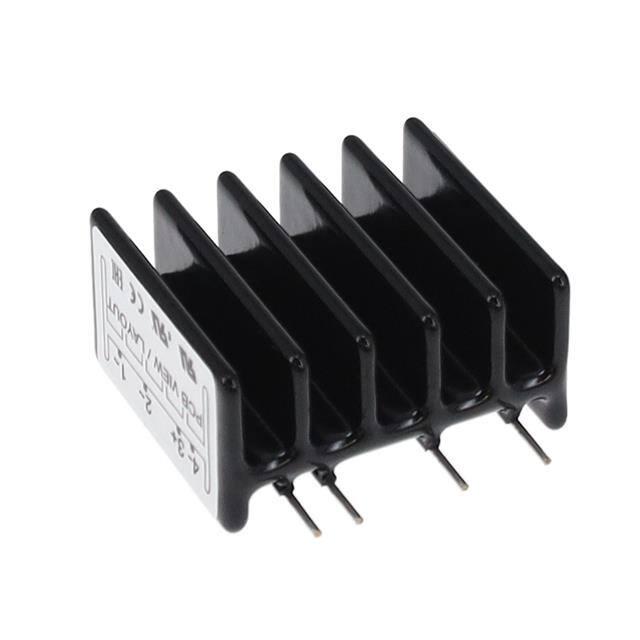
RP1A..D10, RP1B..D10
1-phase PCB mount solid state relays
Main features
• AC Solid State Relay for PCB mounting
• Zero switching or instant-on
• Rated operational current: 10 AACrms (25 AACrms with
forced air cooling)
• Rated operational voltage: Up to 480 VACrms
• Surface mount technology
• Control voltage: 4 to 32 VDC
• Opto-isolation: > 4000 VACrms
• Blocking voltage: Up to 1000 Vp
• Non-repetitive surge current: Up to 250 Ap
Description
The RP1..D10 is an SSR series for socket- or PCBmounting, providing an ideal interface between
logic controls and AC loads.
The RP1..D10 is designed for resistive and
inductive loads up to 480VACrms.
The integral heatsink allows switching of a high
current in this compact package. Opto-isolation
and load switching are performed by individual
components, providing higher reliability. This relay
can also drive high AC53a loads up to 7 AACrms.
The Solid State technology used can withstand
peak voltages of 1000V, making the RP1..D10
series suitable to drive AC loads such as loaded
induction motors.
Applications
These relays can be used to switch heaters, motors, lights, valves or solenoids.
Main functions
• Zero cross or Instant on AC switching
• Ratings up to 480 VACrms, 10 AACrms (25 AACrms with forced air cooling)
• 4-32 VDC control voltage (3-32 VDC for RP1.23D10)
21/04/2017 RP1A..D10, RP1B..D10 DS ENG
Carlo Gavazzi LTD
1
�RP1A..D10, RP1B..D10
References
Order code
RP1
D10
Enter the code entering the corresponding option instead of
Code
R
P
1
Option
A
B
23
40
48
-
D
10
Description
Notes
Solid State Relay (PCB)
Number of poles
Switching mode: zero switching
Switching mode: instant-On switching
Rated operational voltage: 230 VACrms
Rated operational voltage: 400 VACrms
Rated operational voltage: 480 VACrms
Control voltage: 4 to 32 VDC
Rated operational current: 10AACrms
3 to 32 VDC for RP1.23D10
Selection guide
Rated operational voltage
Blocking voltage
Control voltage
230 VACrms
400 VACrms
480 VACrms
650 Vp
850 Vp
1000 Vp
3 to 32 VDC
4 to 32 VDC
4 to 32 VDC
Rated operational current
10 AACrms
RP1A23D10
RP1A40D10
RP1A48D10
CARLO GAVAZZI compatible components
Purpose
Component name/code
DIN adaptors
RPM2
21/04/2017 RP1A..D10, RP1B..D10 DS ENG
Notes
DIN adaptor 600V with LED
Note that when the RP..10 is mounted on DIN rail (vertical mounting),
a derating factor has to be applied.
Carlo Gavazzi LTD
2
�RP1A..D10, RP1B..D10
Features
General
Material
Weight
Isolation: input to output
Black Epoxy coating
Approx. 40 g
4 kVACrms
Dimensions
11 M
22 mm
18 mm
9M
3M
4M
22 mm
37 mm
43 mm
M = 2.54 mm = 1/10 “
21/04/2017 RP1A..D10, RP1B..D10 DS ENG
Carlo Gavazzi LTD
3
�RP1A..D10, RP1B..D10
Performance
Mains supply
Operational voltage range
RP1A
RP1B
Operational frequency range
Blocking voltage
Zero voltage turn-on
RP1.23D10
RP1.40D10
RP1.48D10
12 - 265 VACrms
12 - 265 VACrms
20 - 440 VACrms
12 - 440 VACrms
45 - 65 Hz
< 850 Vp
< 10 VACrms
20 - 530 VACrms
12 - 530 VACrms
< 650 Vp
< 1000 Vp
Outputs
Rated operational current
AC 51 @ Ta = 25°C
AC 53a @ Ta = 25°C
Min. operational load current
Power factor
Rep. overload current t=1 s
Non-rep. surge current t=20 ms
Off-state leakage current @
rated voltage and frequency
I2t for fusing t=10 ms
Critical dV/dt off state min.
On-state voltage drop @ rated
current
10 AACrms
7 AACrms
10 mAACrms
> 0.5
16 AACrms
250 Ap
< 3 mAACrms
340 A2s
1000 V/μs
< 1.5 VACrms
Inputs
Control voltage
RP1.23D10
RP1.40D10, RP1.48D10
Pick-up voltage
RP1.23D10
RP1.40D10, RP1.48D10
Drop-out voltage
Max. input curent
RP1A..D10
RP1B..D10
Max. reverse voltage
Response time pick-up
RP1A..D10
RP1A..D10 @ Vin 5VDC
Response time drop-out
RP1B..D10
RP1B..D10 @ Vin 5VDC
21/04/2017 RP1A..D10, RP1B..D10 DS ENG
3-32 VDC
4-32 VDC
2.8 VDC
3.8 VDC
1.2 VDC
10 mA
17 mA
32 VDC
≤ 1/2 cycle
≤ 200 μs
≤ 1/2 cycle
≤ 1/2 cycle
Carlo Gavazzi LTD
4
�RP1A..D10, RP1B..D10
Derating curve
Load current [AACrms]
Load current [AACrms]
12
30
10
25
8
20
6
15
4
10
2.5ACrms
2.5 AACrms
2
0
12AACrms
5
0
20
30
40
50
60
70
80
20
Surrounding
Surroundingtemperature
temperature[¡C]
˚C
Fig. 1 Convection cooling
30
40
50
60
70
80
Surrounding temperature [°C]
Fig. 2 Forced air cooling at 15m3/h
Derating curve is used for finding max. load current at an elevated ambient temperature.
Note: the above indicated current ratings apply only for the RP..10 mounted with fins in the vertical orientation
to allow airflow through the heatsink fins. For other mounting orientations please consult your Carlo Gavazzi
Sales representative.
Thermal data
Operating temperature
Storage temperature
-30° to +80°C (-22° to +176°F)
-40° to +100°C (-40° to +212°F)
Compatibility and conformity
Standards compliance
LVD: EN 60947-4-3
EMCD: EN 61000-6-2, EN 61000-6-4
UL508
C22.2 No. 14-13
Approvals
21/04/2017 RP1A..D10, RP1B..D10 DS ENG
Carlo Gavazzi LTD
5
�
RP1A..D10, RP1B..D10
Electromagnetic compatibility (EMC) - immunity
EN/IEC 61000-4-2
Electrostatic discharge (ESD)
8 kV air discharge, 4 kV contact (PC1)
EN/IEC 61000-4-3
10 V/m, from 80 MHz to 1 GHz (PC1)
Radiated radio frequency
10 V/m, from 1.4 to 2 GHz (PC1)
10 V/m, from 2 to 2.7 GHz (PC1)
EN/IEC 61000-4-4
Electrical fast transient (burst) Output: 2 kV, 5 kHz (PC2)
Input: 1 kV, 5 kHz (PC2)
EN/IEC 61000-4-6
Conducted radio frequency
10V/m, from 0.15 to 80 MHz (PC1)
EN/IEC 61000-4-5
Output, line to line: 1 kV (PC2)
Electrical surge
Output, line to earth: 1 kV (PC2)1
Input, line to line: 500 V (PC2)2
Input, line to earth: 500 V (PC2)2
EN/IEC 61000-4-11
0% for 0.5, 1 cycle (PC2)
Voltage dips
40% for 10 cycles (PC2)
70% for 25 cycles (PC2)
EN/IEC 61000-4-11
Voltage Interruptions
0% for 5000ms (PC2)
Electromagnetic compatibility (EMC) - emissions
Radio interference field emisEN/IEC 55011
sion (radiated)
Class A: from 30 to 1000 MHz
From 0.15 to 30 MHz
EN/IEC 55011
Radio interference voltage
Class A (industrial) with filter capacitor across the Mains supply
emissions (conducted)
EN/IEC 60947-4-3
Class A (no filtering needed)
Note:
• Performance Criteria 1 (PC1): no degradation of performance or loss of function is allowed when the product is operated
as intended.
• Performance Criteria 2 (PC2): during the test, degradation of performance or partial loss of function is allowed. However
when the test is complete the product should return operating as intended by itself.
• Performance Criteria 3 (PC3): temporary loss of function is allowed, provided the function can be restored by manual
operation of the controls.
• Control input lines must be installed together to maintain products' susceptability to Radio Frequency interference.
• 1 A suppression device, such as a varistor, needs to be connected across the output terminals L1, T1 for immunity against
higher voltage levels.
• 2 A suppression device, such as a transil, needs to be connected across the control terminals A1, A2 for immunity against
higher voltage levels.
21/04/2017 RP1A..D10, RP1B..D10 DS ENG
Carlo Gavazzi LTD
6
�RP1A..D10, RP1B..D10
Functional diagram
(+) 3
1
REGULATION
ZC
Control
input
*
IO
2
(-) 4
ZC - Zero Crossing
IO - Instant On
* The varistor is not included in the solid state relay. Connecting a varistor across terminals 1-2 helps protect
the solid state relay against damages by over-voltage
Connection specifications
Terminals
Terminals soldering temperature
Copper alloy, tin-plated
max. 300°C for 5 seconds
COPYRIGHT ©2017
Content subject to change. Download the PDF: www.productselection.net
21/04/2017 RP1A..D10, RP1B..D10 DS ENG
Carlo Gavazzi LTD
7
�