Technical Data 10520
Effective April 2017
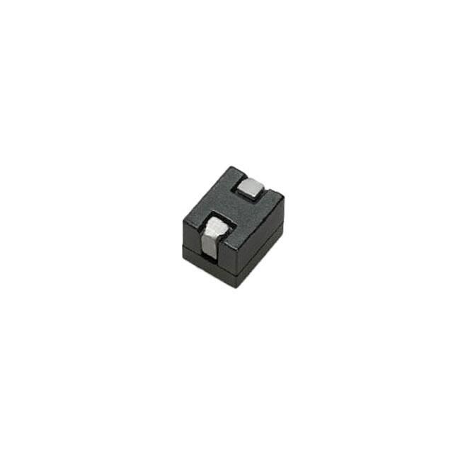
FP1008R5 and FP1008R6
High frequency, high current power inductors
Applications
Product features
•
High current carrying capacity
•
Low core loss
•
Magnetically shielded
•
Tight tolerance DCR for sensing circuits
•
Inductance Range from 100 nH to 300 nH
•
Current range from 36 A to 103 A
•
10.8 mm x 8.0 mm footprint surface mount
package in an 8.0 mm height
•
Moisture Sensitivity Level: 1
•
Ferrite core material
•
Multi-phase and Vcore regulators
•
Voltage Regulator Modules (VRMs) and high
power density VRMs
• Server and desktop
•
Central processing unit (CPU)
•
Graphics processing unit (GPU)
•
Application specific integrated circuit (ASIC)
•
Data networking and storage systems
•
Graphics cards and battery power systems
•
Point-of-Loadmodules (POL)
•
DCR sensing circuits
Environmental data
•
Storage temperature range (Component):
-40 °C to +125 °C
•
Operating temperature range: -40 °C to +125 °C
(ambient plus self-temperature rise)
•
Solder reflow temperature:
J-STD-020 (latest revision) compliant
•
Halogen free, lead free, RoHS compliant
HALOGEN
Pb HF
FREE
�FP1008R5 and FP1008R6
High frequency, high current power inductors
Technical Data 10520
Effective April 2017
Product specifications
OCL1
(nH) ±10%
FLL2
(nH) minimum
Irms3
(A)
Isat14
(A)
Isat25
(A)
Isat36
(A)
DCR (mΩ)
±5% @ 20 °C
K-factor7
FP1008R5-R120-R
120
86
79
103
90
84
0.170
342
FP1008R5-R150-R
150
108
79
85
68
64
0.170
342
FP1008R5-R180-R
180
130
79
70
56
53
0.170
342
FP1008R5-R220-R
220
158
79
58
44
42
0.170
342
FP1008R5-R270-R
270
194
79
44
34
32
0.170
342
FP1008R5-R300-R
300
216
79
36
28
26
0.170
342
FP1008R6-R100-R
100
72
74
103
86
81
0.180
342
FP1008R6-R120-R
120
86
74
103
90
84
0.180
342
FP1008R6-R150-R
150
108
74
85
68
64
0.180
342
Part Number8
R5 version
R6 version
FP1008R6-R180-R
180
130
74
70
56
53
0.180
342
FP1008R6-R220-R
220
158
74
58
44
42
0.180
342
FP1008R6-R270-R
270
194
74
44
34
32
0.180
342
FP1008R6-R300-R
300
216
74
36
28
26
0.180
342
1. Open Circuit Inductance (OCL) Test Parameters: 100 kHz, 0.1 Vrms, 0.0 Adc, +25 °C
2. Full Load Inductance (FLL) Test Parameters: 100 kHz, 0.1 Vrms, Isat1, +25 °C
3. Irms: DC current for an approximate temperature rise of 40 °C without core loss. Derating is
necessary for AC currents. PCB layout, trace thickness and width, air-flow, and proximity of
other heat generating components will affect the temperature rise. It is recommended that the
temperature of the part not exceed 125 °C under worst case operating conditions verified in the
end application.
4. Isat1: Peak current for approximately 20% rolloff @ +25 °C
5. Isat2: Peak current for approximately 20% rolloff @ +100 °C
6. Isat3: Peak current for approximately 20% rolloff @ +125 °C
7. K-factor: Used to determine Bp-p for core loss (see graph).
Bp-p = K * L * ∆I * 10-3. Bp-p:(Gauss), K: (K-factor from table), L:
(Inductance in nH), ∆I (Peak to peak ripple current in Amps).
8. Part Number Definition: FP1008Rx-Rxxx-R
FP1008R= Product code and size
x= Version indicator
-Rxxx= Inductance value in uH, R= decimal point
-R suffix = RoHS compliant
Dimensions (mm)
Part marking: FP1008Rx (x = Version), Rxxx= Inductance value in uH (R= decimal point) xxxx = Lot code
Tolerances are ±0.15 millimeters unless stated otherwise
Pad layout tolerances are ±0.1 millimeters unless stated otherwise
All soldering surfaces to be coplanar within 0.1 millimeter
DCR measured from point “A” to point “B”
Do not route traces or vias underneath the inductor
2
www.eaton.com/electronics
�FP1008R5 and FP1008R6
High frequency, high current power inductors
Technical Data 10520
Effective April 2017
Packaging information (mm)
Supplied in tape-and-reel packaging, 500 parts on a 13” diameter reel.
Temperature rise vs total loss
FP1008R6
60
60
50
50
Temperature Rise (°C)
Temperature Rise (°C)
FP1008R5
40
30
20
30
20
10
10
0
40
0.0
0.2
0.4
0.6
0.8
Total Loss (W)
1.0
1.2
1.4
1.6
0
0.0
0.2
0.4
0.6
0.8
Total Loss (W)
1.0
1.2
www.eaton.com/electronics
1.4
1.6
3
�FP1008R5 and FP1008R6
High frequency, high current power inductors
Technical Data 10520
Effective April 2017
Core loss vs. Bp-p
FP1008R5
1
0.1
Core Loss (W)
Core Loss (W)
0.1
0.01
0.001
0.0001
FP1008R6
1
0.01
0.001
100
1000
0.0001
10000
Bp-p (Gauss)
100
1000
10000
Bp-p (Gauss)
Inductance characteristics
FP1008R5-R120-R
140
140
120
120
Inductance (nH)
Inductance (nH)
100
80
60
-40 °C
40
+25 °C
4
20
40
80
60
-40 °C
+25 °C
+100 °C
20
+125 °C
0
100
40
+100 °C
20
0
FP1008R5-R150-R
160
60
www.eaton.com/electronics
Idc (A)
80
100
120
140
0
+125 °C
0
20
40
60
Idc (A)
80
100
120
�FP1008R5 and FP1008R6
High frequency, high current power inductors
Technical Data 10520
Effective April 2017
Inductance characteristics
FP1008R5-R180-R
200
FP1008R5-R220-R
240
180
200
160
Inductance (nH)
Inductance (nH)
140
120
100
80
80
+25 °C
+100 °C
20
40
+100 °C
+125 °C
0
10
20
+125 °C
30
40
50
Idc (A)
60
70
80
90
0
100
FP1008R5-R270-R
320
0
10
20
40
Idc (A)
50
60
70
80
FP1008R5-R300-R
300
240
250
Inductance (nH)
200
160
120
-40 °C
80
200
150
-40 °C
100
+25 °C
+100 °C
40
+25 °C
+100 °C
50
+125 °C
+125 °C
0
10
20
30
Idc (A)
40
50
60
0
70
FP1008R6-R100-R
120.0
0
10
20
30
Idc (A)
40
50
60
FP1008R6-R120-R
140
120
100.0
Inductance (nH)
100
Inductance (nH)
80.0
60.0
40.0
80
60
-40 °C
40
-40 °C
+25 °C
+25 °C
20.0
+100 °C
20
+100 °C
+125 °C
+125 °C
0.0
30
350
280
Inductance (nH)
-40 °C
+25 °C
40
0
120
-40 °C
60
0
160
0
20
40
60
80
Idc (A)
100
120
140
160
0
0
20
40
60
Idc (A)
80
100
120
www.eaton.com/electronics
140
5
�FP1008R5 and FP1008R6
High frequency, high current power inductors
Technical Data 10520
Effective April 2017
Inductance characteristics
FP1008R6-R150-R
160
FP1008R6-R180-R
200
180
140
160
Inductance (nH)
Inductance (nH)
120
100
80
60
40
120
100
60
+25 °C
40
20
40
60
80
Idc (A)
100
0
120
FP1008R6-R220-R
240
-40 °C
+25 °C
+100 °C
20
+125 °C
0
80
-40 °C
+100 °C
20
0
140
+125 °C
0
10
20
30
40
50
Idc (A)
60
70
80
90
100
FP1008R6-R270-R
320
280
200
160
Inductance (nH)
Inductance (nH)
240
120
80
+100 °C
0
10
20
30
40
Idc (A)
50
60
70
80
FP1008R6-R300-R
250
200
150
-40 °C
100
+25 °C
+100 °C
50
+125 °C
0
10
20
www.eaton.com/electronics
+25 °C
+100 °C
+125 °C
300
Inductance (nH)
-40 °C
40
+125 °C
350
6
120
80
+25 °C
0
160
-40 °C
40
0
200
30
Idc (A)
40
50
60
0
0
10
20
30
Idc (A)
40
50
60
70
�FP1008R5 and FP1008R6
High frequency, high current power inductors
Technical Data 10520
Effective April 2017
Solder reflow profile
TP
TC -5°C
tP
Max. Ramp Up Rate = 3°C/s
Max. Ramp Down Rate = 6°C/s
Temperature
TL
Preheat
A
T smax
t
Table 1 - Standard SnPb Solder (Tc)
Package
Thickness
Volume
mm3
很抱歉,暂时无法提供与“FP1008R5-R150-R”相匹配的价格&库存,您可以联系我们找货
免费人工找货- 国内价格 香港价格
- 500+11.41084500+1.47420
- 1000+10.761011000+1.39024
- 1500+10.398621500+1.34342
- 2500+9.959962500+1.28675
- 3500+9.681453500+1.25077
- 5000+9.395045000+1.21377
- 国内价格 香港价格
- 1+19.200711+2.48058
- 10+15.7556510+2.03551
- 100+12.95382100+1.67354