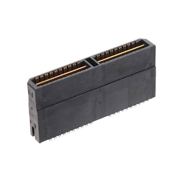
F-218 (Rev 10OCT17)
QTH–090–01–C–D–A
®
QTH–030–01–L–D–A
QTH–060–07–F–D–A
(0.50 mm) .0197"
QTH SERIES
HIGH-SPEED GROUND PLANE HEADER
Board Mates:
10 YEAR MFG
WITH 50 µ" GOLD
QSH
EXTENDED LIFE
Cable Mates:
PRODUCT
HQCD, HQDP
HIGH MATING
CYCLES
(See Also Available Note)
Standoffs:
SO
SPECIFICATIONS
For complete specifications and
recommended PCB layouts see
www.samtec.com?QTH
Insulator Material:
Liquid Crystal Polymer
Terminal Material:
Phosphor Bronze
Plating:
Au or Sn over 50 µ" (1.27 µm) Ni
Current Rating:
Contact:
2 A per pin
(2 pins powered)
Ground Plane:
25 A per ground plane
(1 ground plane powered)
Operating Temp Range:
-55 °C to +125 °C
Voltage Rating:
125 VAC (5 mm Stack Height)
Max Cycles:
100
RoHS Compliant:
Yes
Integral metal plane for
power or ground
Standard Stack Heights
from 5 mm to 25 mm
POWER/SIGNAL
APPLICATION
ALSO AVAILABLE
(MOQ Required)
• 15 mm, 22 mm and
30 mm stack height
• 30 µ" (0.76 µm) Gold
(Specify -H plating for Data Rate
cable mating applications.)
• Edge Mount & Guide Posts
• 80 (-DP), 120, 150 positions per row
• Retention Option
Contact Samtec.
HIGH-SPEED CHANNEL PERFORMANCE
QTH/QSH @ 5 mm Mated Stack Height
Rating based on Samtec reference channel.
For full SI performance data visit Samtec.com
or contact SIG@samtec.com
PROCESSING
Lead–Free Solderable:
Yes
SMT Lead Coplanarity:
(0.10 mm) .004" max (030-060)
(0.15 mm) .006" max (090)*
*(.004" stencil solution
may be available; contact
IPG@samtec.com)
Board Stacking:
For applications requiring
more than two connectors per
board contact ipg@samtec.com
LEAD
STYLE
PINS PER ROW
NO. OF PAIRS
QTH
Specify
LEAD
STYLE
from
chart
–030, –060, –090
(60 total pins per bank = –D)
–020, –040, –060
(20 pairs per bank = –D–DP)
RECOGNITIONS
–D = (No. of Pins per Row/30) x (20.00) .7875
01
FILE NO. E111594
• 100 GbE
• Hypertransport™
• XAUI
• PCI Express®
• SATA
• InfiniBand™
–F
= Gold Flash on
Signal Pins and
Ground Plane,
Matte Tin on tails
02
(0.50)
.0197
(0.20)
.008
A
A
–01 & –02
(0.76)
.030
(0.89)
.035
DIA
= Electro-Polished
Selective
50 µ" (1.27 µm) min Au
over 150 µ" (3.81 µm)
Ni on Signal Pins in
contact area,
10 µ" (0.25 µm) min Au
over 50 µ" (1.27 µm)
Ni on Ground Plane
in contact area,
Matte Tin over 50 µ"
(1.27 µm) min Ni
on all solder tails
*Note: –C Plating passes
10 year MFG testing
–L
A
TYPE
(0.64)
.025
= Single-Ended
–D–DP
= Differential Pair
(–01 only)
= (7.00 mm)
.275" DIA
Polyimide
film Pick &
Place Pad
(N/A with -05 &
-07 lead style)
–TR
= Tape & Reel
(–090 positions
maximum)
–L
QTH
LEAD
STYLE
–01
–02
–03
–04
–05
–07
–09
A
HEIGHT
WITH
QSH*
(4.27)
.168
(7.26)
.286
(10.27)
.404
(15.25)
.600
(18.26)
.718
(24.24)
.954
(13.26)
.522
(5.00)
.197
(8.00)
.315
(11.00)
.433
(16.00)
.630
(19.00)
.748
(25.00)
.984
(14.00)
.551
*Processing conditions
will affect mated height.
See SO Series for
board space tolerances
Due to technical progress, all designs, specifications and components are subject to change without notice.
WWW.SAMTEC.COM
OTHER
OPTION
–K
–D
–C*
(7.11)
.280
–03 thru –09
Note:
Some lengths, styles and
options are non-standard,
non-returnable.
PLATING
OPTION
= 10 µ" (0.25 µm)
Gold on Signal Pins
and Ground Plane,
Matte Tin on tails
–DP = (No. of Pairs per Row/20) x (20.00) .7875
(20.00) .7875
G b p s
–L
For complete scope of
recognitions see
www.samtec.com/quality
PROTOCOLS
25
Compatible with
UMPT/UMPS for
flexible two-piece
power/signal solutions
All parts within this catalog are built to Samtec’s specifications.
Customer specific requirements must be approved by Samtec and identified in a Samtec customer-specific drawing to apply.
= Latching
Option
(–01 lead
style only)
(N/A on
–060 (–D–DP)
& –090)
�
QTH-040-05-L-D-DP-A 价格&库存
很抱歉,暂时无法提供与“QTH-040-05-L-D-DP-A”相匹配的价格&库存,您可以联系我们找货
免费人工找货- 国内价格
- 1+102.43800
- 10+97.66440
- 36+89.39160
- 108+82.17720
- 国内价格 香港价格
- 1+143.996681+18.71911