a d ivision of CUI INC
date 03/2011 page 1 of 5
SERIES:
VLED15
DESCRIPTION:
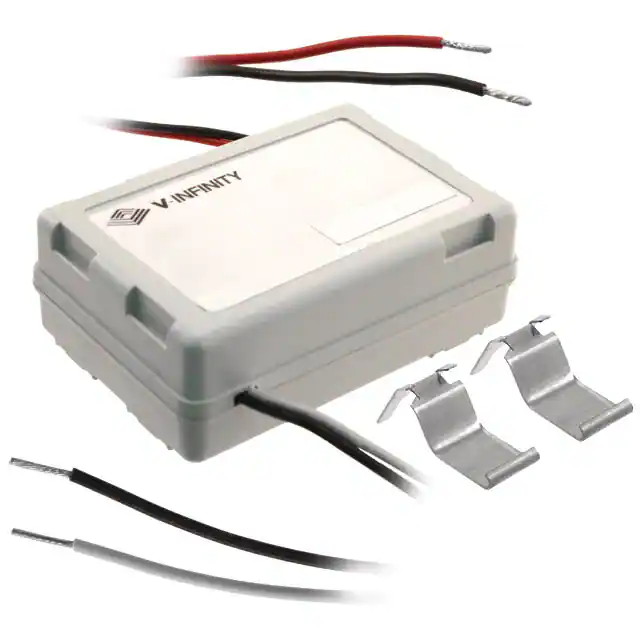
LED DRIVER
FEATURES
•constant current •high efficiency •120 and 230 V ac inputs available •0.35 ~ 1.5 A output current •operates with industry standard dimmers •compact encapsulated assembly •active power factor correction •over voltage, over current, over temperature, short circuit protection: auto recovery •high temperature operation (up to 90°C case) •UL approved, ENEC approved, CE Mark •long life > 50,000 hours
RoHS
outut voltage1
min. (V dc) max. (V dc)
MODEL
VLED15-120-350 VLED15-120-480 VLED15-120-600 VLED15-120-700 VLED15-120-800 VLED15-120-900 VLED15-120-900L VLED15-120-1000 VLED15-120-1200 VLED15-120-1250 VLED15-120-1400 VLED15-120-1500 VLED15-230-350 VLED15-230-480 VLED15-230-600 VLED15-230-700 VLED15-230-800 VLED15-230-900 VLED15-230-900L VLED15-230-1000 VLED15-230-1200 VLED15-230-1250 VLED15-230-1400 VLED15-230-1500
notes:
2 2
output current
max. (mA)
ouput power
max. (W)
input voltage
nominal load (V ac)
24 10 8 16 8 10 8 10 10 8 8 5 24 10 8 16 8 10 8 10 10 8 8 5
48 13.5 12 24 12 16 12 16 14.1 12 11.5 10 48 13.5 12 24 12 16 12 16 14.1 12 11.5 10
350 480 600 700 800 900 900 1,000 1,200 1,250 1,400 1,500 350 480 600 700 800 900 900 1,000 1,200 1,250 1,400 1,500
16.8 6.5 7.2 16.8 9.6 14.4 10.8 16 16.92 15 16.1 15 16.8 6.5 7.2 16.8 9.6 14.4 10.8 16 16.92 15 16.1 15
115 115 115 115 115 115 115 115 115 115 115 115 230 230 230 230 230 230 230 230 230 230 230 230
1. total LED forward voltage must be within these ratings under all conditions including dimming 2. 80°C maximum case rating
20050 SW 112th Ave. Tualatin, Oregon 97062
phone 503.612.2300
fax 503.612.2382 www.v-infinity.com
�a d ivision of CUI INC
date 03/2011 page 2 of 5
SERIES:
VLED15
DESCRIPTION:
LED DRIVER
INPUT
parameter current frequency range power factor harmonics inrush current 120 V ac meets EN61000-3-2, 3 25°C 5 A conditions/description 115 V ac 47 90 min nom max 0.22 63 units A Hz %
OUTPUT
parameter voltage accuracy load regulation over voltage protection over current protection short circuit protection control dimming range (conduction angle/output) auto restart auto restart auto restart output dims without any flicker use with incandescent dimmer 30 147 degrees conditions/description of set point min nom ±5 ±5 max units % %
SAFETY & COMPLIANCE
parameter safety approvals EMC/EMI conditions/description UL60950-1, LPS, UL8750, EN61347-2-13 EN55015 class B, FCC class 47 CFR part 15 class B, EN61000-4-(2,3,4,5,6,11), IEC 61000-3-(2,3) ANSI c62.41-1991 category A1, 2.5 kV Ringwave yes 120 V ac 0.25 mA min nom max units
RoHS compliant leakage current
ENVIRONMENTAL
parameter operating temperature operating humidity storage temperature surface temperature over temperature protection exposed surfaces, under all operating conditions auto restart conditions/description case temperature without derating non-condensing min -30 5 -40 nom max 90 95 85 90 units °C % °C °C
RELIABILITY
parameter MTBF conditions/description at 90°C case temperature, electrolytic life min 50,000 nom max units hours
20050 SW 112th Ave. Tualatin, Oregon 97062
phone 503.612.2300
fax 503.612.2382 www.v-infinity.com
�a d ivision of CUI INC
date 03/2011 page 3 of 5
SERIES:
VLED15
DESCRIPTION:
LED DRIVER
ISOLATION SPECIFICATIONS
parameter isolation conditions/description meets the UL60950-1 reinforced, double insulation NEC (Class 2) EN60598-1 class II min nom max units
DIMMING REQUIREMENTS
Dimming of the driver shall be possible with standard triac based incandescent dimmers that chops the AC voltage as shown below or with Electronic Low Voltage dimmers that employ reverse phase control.
Chopped AC Input to Driver
AC Wall Power
During the rapid rise time of the AC voltage when the dimmer turns on, the driver shall not generate any voltage or current oscillations and inrush current shall be controlled. During the on time of the AC input, the driver shall regulate the output. The RMS value of the driver output current shall be proportional to the on time of the AC input voltage. Care must be taken to assure that the minimum load requirements are met. Multiple drivers/LEDs may be connected to the dimmer in order to meet the minimum load requirement.
DIMMING RANGE
When operating with an incandescent dimmer, the RMS output current shall vary depending upon the conduction angle and RMS value of the applied AC input voltage. The following graph shows the typical output versus conduction angle at various line voltages.
Typical Io vs Conduc on Angle
1.2 Output Current (A) Normalized to I Set 1 0.8 0.6 0.4 0.2 0 0 20 40 60 80 100 120 140 160 VAC Conduc on Angle (Degrees) 100V (200V) 115V (230V) 132V (264V)
The specified dimming range shall be from 30 degrees through 147 degrees conduction angle. Operation throughout this dimming range shall be monotonic and produce a smooth transition of light output in both directions of the dimming range. At 120 V ac or 240 V ac input, the driver shall achieve full rated output current at less than 147 degree conduction angle.
20050 SW 112th Ave. Tualatin, Oregon 97062
phone 503.612.2300
fax 503.612.2382 www.v-infinity.com
�a d ivision of CUI INC
date 03/2011 page 4 of 5
SERIES:
VLED15
DESCRIPTION:
LED DRIVER
DIMMING REQUIREMENTS
The VLED15 series of drivers operate from either 90VAC to 135 V ac or 176 V ac to 265 V ac, at 47 to 63 Hz. The drivers will operate at voltages down to 20 V ac for the 120 V versions and 40 V for the 240 V ac versions. The following graph shows the typical output current versus AC input voltage without a dimmer attached and with a typical LED as the load. Nominal output current shall be achieved at
很抱歉,暂时无法提供与“VLED15-230-900L”相匹配的价格&库存,您可以联系我们找货
免费人工找货