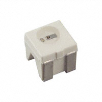
Leistungsstarke IR-Lumineszenzdiode High Power Infrared Emitter SFH 4200 SFH 4205
SFH 4200
SFH 4205
Wesentliche Merkmale • • • • • • Leistungsstarke GaAs-LED (35mW) Hoher Wirkunsgrad bei kleinen Strömen Homogene Abstrahlung Typische Peakwellenlänge 950nm IR Reflow und TTW Löten geeignet Feuchte-Empfindlichkeitsstufe 2 nach JEDEC Standard J-STD-020A
Features • • • • • • High Power GaAs-LED (35mW) High Efficiency at low currents Homogeneous Radiation Pattern Typical peak wavelength 950nm Suitable for IR reflow and TTW soldering Moisture Sensitivity Level 2 according to JEDEC Standard J-STD-020A
Anwendungen • Schnelle Datenübertragung mit Übertragungsraten bis 100 Mbaud (IR Tastatur, Joystick, Multimedia) • Analoge und digitale Hi-Fi Audio- und Videosignalübertragung • Alarm- und Sicherungssysteme • IR Freiraumübertragung • IR-Scheinwerfer für Kameras
Applications • High data transmission rate up to 100 Mbaud (IR keyboard, Joystick, Multimedia) • Analog and digital Hi-Fi audio and video signal transmission • Alarm and safety equipment • IR free air transmission • IR spotlight for cameras
Typ Type SFH 4200 SFH 4205
1)
Bestellnummer Strahlstärkegruppierung 1) (IF = 100mA, tp = 20 ms) Ordering Code Radiant intensity grouping 1) Ie (mW/sr) Q62702-P978 Q62702-P5165 10.5 (>4) 10.5 (>4)
gemessen bei einem Raumwinkel Ω = 0.01 sr measured at a solid angle of Ω = 0.01 sr
2003-12-09
1
�SFH 4200, SFH 4205
Grenzwerte (TA = 25 °C) Maximum Ratings Bezeichnung Parameter Betriebs- und Lagertemperatur Operating and storage temperature range Sperrspannung Reverse voltage Durchlaßstrom Forward current Stoßstrom, tp = 10 µs, D = 0 Surge current Verlustleistung Power dissipation Symbol Symbol Wert Value – 40 … + 100 3 100 2.2 180 450 Einheit Unit °C V mA A mW K/W
Top; Tstg VR IF (DC) IFSM Ptot
Wärmewiderstand Sperrschicht - Umgebung bei RthJA Montage auf FR4 Platine, Padgröße je 16 mm2 Thermal resistance junction - ambient mounted on PC-board (FR4), padsize 16 mm2 each Wärmewiderstand Sperrschicht - Lötstelle bei RthJS Montage auf Metall-Block Thermal resistance junction - soldering point, mounted on metal block
200
K/W
2003-12-09
2
�SFH 4200, SFH 4205
Kennwerte (TA = 25 °C) Characteristics Bezeichnung Parameter Wellenlänge der Strahlung Wavelength at peak emission IF = 100 mA, tp = 20 ms Spektrale Bandbreite bei 50% von Imax Spectral bandwidth at 50% of Imax IF = 100 mA, tp = 20 ms Abstrahlwinkel Half angle Aktive Chipfläche Active chip area Abmessungen der aktiven Chipfläche Dimensions of the active chip area Symbol Symbol λpeak Wert Value 950 Einheit Unit nm
∆λ
40
nm
ϕ
± 60 0.09 0.3 × 0.3 10
Grad deg. mm2 mm ns
A L×B L×W
Schaltzeiten, Ie von 10% auf 90% und von 90% tr, tf auf 10%, bei IF = 100 mA, tp = 20 ms, RL = 50 Ω Switching times, Ιe from 10% to 90% and from 90% to10%, IF = 100 mA, tp = 20 ms, RL = 50 Ω Durchlaßspannung, Forward voltage IF = 100 mA, tp = 20 ms IF = 1 A, tp = 100 µs Sperrstrom, Reverse current VR = 3 V Gesamtstrahlungsfluß, Total radiant flux IF = 100 mA, tp = 20 ms Temperaturkoeffizient von Ie bzw. Φe,
VF VF IR
1.5 (≤ 1.8) 3.2 (≤ 4.3) 0.01 (≤ 10)
V V µA
Φe
35
mW
TCI
– 0.44
%/K
IF = 100 mA
Temperature coefficient of Ie or Φe, IF = 100 mA
Temperaturkoeffizient von VF, IF = 100 mA Temperature coefficient of VF, IF = 100 mA Temperaturkoeffizient von λ, IF = 100 mA Temperature coefficient of λ, IF = 100 mA
TCV TCλ
– 1.5 + 0.2
mV/K nm/K
2003-12-09
3
�SFH 4200, SFH 4205
Strahlstärke Ie in Achsrichtung gemessen bei einem Raumwinkel Ω = 0.01 sr Radiant Intensity Ie in Axial Direction at a solid angle of Ω = 0.01 sr Bezeichnung Parameter Strahlstärke Radiant intensity IF = 100 mA, tp = 20 ms Strahlstärke Radiant intensity IF = 1 A, tp = 100 µs Symbol Ie min. Ie typ. Ie typ. Werte Values 4 10.5 60 Einheit Unit mW/sr mW/sr mW/sr
2003-12-09
4
�SFH 4200, SFH 4205
Relative Spectral Emission Irel = f (λ)
100
OHF00777
Radiant Intensity
Ie = f (IF ) Ie 100 mA
Single pulse, tp = 20 µs
10 2 Ιe
OHF00809
Max. Permissible Forward Current IF = f (T A )
120
OHF00359
Ι erel
80
ΙF
mA 100
Ι e (100 mA)
80
60
10 0
R thJA = 375 K/W 60
40
10 -1
40
20
10
-2
20
10 -3 10 0
0
800 850
900
950 1000
nm 1100
10 1
10 2
λ
10 3 mA 10 4 ΙF
0
0
20
40
60
80
100 ˚C 120 TA
Forward Current IF = f (VF) single pulse, tp = 20 µs
10 4 mA 10
3 OHF00784
Permissible Pulse Handling Capability IF = f (τ), TA = 25 °C, duty cycle D = parameter
IF
101 A 5
OHF00040
ΙF
P D= T
t
tP
IF T D=
0.005 0.01 0.02 0.05 0.1 0.2 0.5 1
10 2 10 1 10 0
100 5
10 -1 10 -2 10 -3
0 0.5 1 1.5 2 2.5 3 3.5
V 4.5
10-1 -5 10 10-4 10-3 10-2 10-1 100 101 s 10 2
VF
tp
10˚ 0˚
Radiation Characteristics Irel = f (ϕ
40˚ 30˚ 20˚
OHL01660
ϕ
1.0
50˚
0.8
0.6 60˚ 0.4 70˚ 0.2 80˚ 90˚ 100˚ 1.0 0.8 0.6 0.4 0˚ 20˚ 40˚ 60˚ 80˚ 100˚ 120˚ 0
2003-12-09
5
�SFH 4200, SFH 4205
Maßzeichnung Package Outlines
SFH 4200
3.0 (0.118) 2.6 (0.102) 2.3 (0.091) 2.1 (0.083)
2.1 (0.083) 1.7 (0.067) 0.1 (0.004) (typ.) 0.9 (0.035) 0.7 (0.028)
(2.4) (0.095)
1.1 (0.043)
3.7 (0.146) 3.3 (0.130) 4˚±1 0.5 (0.020)
Cathode marking
3.4 (0.134) 3.0 (0.118)
0.18 (0.007) 0.12 (0.005)
0.6 (0.024) 0.4 (0.016)
GPLY6724
SFH 4205
(2.4 (0.094))
2.8 (0.110)
2.4 (0.094)
4.2 (0.165) 3.8 (0.150)
0.7 (0.028)
1.1 (0.043) Cathode 2.54 (0.100) spacing (1.4 (0.055)) 0.9 (0.035) Anode
(2.85 (0.112))
Cathode marking
(0.3 (0.012))
(2.9 (0.114))
(R1)
4.2 (0.165) 3.8 (0.150)
3.8 (0.150) 3.4 (0.134)
GPLY6880
Maße werden wie folgt angegeben: mm (inch) / Dimensions are specified as follows: mm (inch)
2003-12-09
6
�SFH 4200, SFH 4205
Löthinweise Soldering Conditions Bauform Types Tauch-, Schwall- und Schlepplötung Dip, Wave and Drag Soldering Lötbadtemperatur Reflowlötung Reflow Soldering Maximale Durchlaufzeit Max. Transit Time 10 s
Maximal zulässige LötzonenLötzeit temperatur Temperature of Soldering Zone 245 °C
Max. Perm. Temperature of the Soldering Bath Soldering Time TOPLED SIDELED 260 °C 10 s
Zusätzliche Informationen über allgemeine Lötbedingungen erhalten Sie auf Anfrage. For additional information on general soldering conditions please contact us.
Published by OSRAM Opto Semiconductors GmbH & Co. OHG Wernerwerkstrasse 2, D-93049 Regensburg © All Rights Reserved. Attention please! The information describes the type of component and shall not be considered as assured characteristics. Terms of delivery and rights to change design reserved. Due to technical requirements components may contain dangerous substances. For information on the types in question please contact our Sales Organization. Packing Please use the recycling operators known to you. We can also help you – get in touch with your nearest sales office. By agreement we will take packing material back, if it is sorted. You must bear the costs of transport. For packing material that is returned to us unsorted or which we are not obliged to accept, we shall have to invoice you for any costs incurred. Components used in life-support devices or systems must be expressly authorized for such purpose! Critical components 1 , may only be used in life-support devices or systems 2 with the express written approval of OSRAM OS. 1 A critical component is a component usedin a life-support device or system whose failure can reasonably be expected to cause the failure of that life-support device or system, or to affect its safety or effectiveness of that device or system. 2 Life support devices or systems are intended (a) to be implanted in the human body, or (b) to support and/or maintain and sustain human life. If they fail, it is reasonable to assume that the health of the user may be endangered. 2003-12-09 7
�