rev. page page date date 1 of 11
08/2009
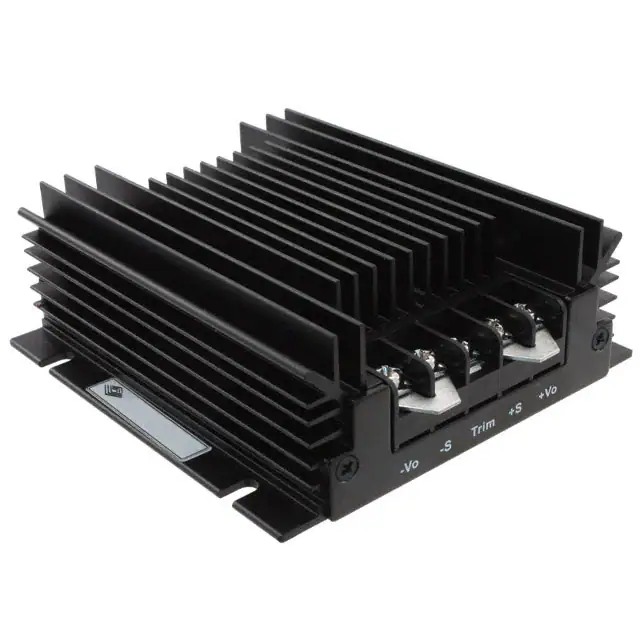
PART NUMBER: VHK50W
DESCRIPTION: chassis mount dc-dc converter
description
The VHK50W series of rugged DC-DC converters are designed for high reliability applications, featuring integral heat sink, over-temperature protection, over-current protection and input transient voltage protection. With an external input fuse, the converter can protect accidental input polarity reversal. The wide 4:1 input range (9-36V or 1875V) is very useful to stabilize an input source like batteries in various discharging and charging conditions. Additionally, high efficiency, fast response, tight regulations, remote sense and remote On/Off control make these converters very useful in many industrial and communications applications.
features
·25-50W isolated output ·Efficiency to 83% ·RoHS Compliant ·4:1 input range ·Regulated output ·Continuous short circuit protection ·Metal enclosure with integrated heatsink ·Rugged design ·Over-temperature shutdown
M ODEL
VHK50W-Q24-S3R3 VHK50W-Q24-S5 VHK50W-Q24-S12 VHK50W-Q24-S15 VHK50W-Q24-S24 VHK50W-Q24-S28 VHK50W-Q24-S48 VHK50W-Q48-S3R3 VHK50W-Q48-S5 VHK50W-Q48-S12 VHK50W-Q48-S15 VHK50W-Q48-S24 VHK50W-Q48-S28 VHK50W-Q48-S48
notes:
input voltage nominal range (V dc) (V dc)
output voltage (V dc)
output current 1 (A)
input current no load 2 full load 2 (mA) (mA)
efficiency typ. 3 (%)
24 24 24 24 24 24 24 48 48 48 48 48 48 48
9.0~36.0 9.0~36.0 9.0~36.0 9.0~36.0 9.0~36.0 9.0~36.0 9.0~36.0 18.0~75.0 18.0~75.0 18.0~75.0 18.0~75.0 18.0~75.0 18.0~75.0 18.0~75.0
3.3 5 12 15 24 28 48 3.3 5 12 15 24 28 48
10 10 4.16 3.33 2.08 1.78 1.04 10 10 4.16 3.33 2.08 1.78 1.04
50 50 50 50 50 50 50 50 50 50 50 50 50 50
1833 2637 2537 2538 2537 2537 2537 905 1302 1267 1265 1264 1264 1253
75 79 82 82 82 82 82 76 80 83 83 83 83 83
1. see output derating curves (page 4) 2. input currents are measured at nominal input voltage 3. efficiency is measured at nominal line, full load
I NPUT
parameter input voltage range under voltage lockout conditions/description min 9 18 nom 24 48 8.8 8 17 16 max 36 75 units V dc V dc V dc V dc V dc V dc
remote on/off control 4 input filter
notes:
24 Vin power up 24 Vin power down 48 Vin power up 48 Vin power down section 15 in the application notes PI type
4. add suffix “N” to the model number for negative logic on/off control
*V-Infinity reserves the right to make changes to its products or to discontinue any product or service without notice, and to advise customers to verify the most up-todate product information before placing orders. V-Infinity assumes no liability or responsibility for customer’s applications using V-Infinity products other than repair or replacing (at V-I’s option) V-Infinity products not meeting V-I’s published specifications. Nothing will be covered outside of standard product warranty.
20050 SW 112th Ave. Tualatin, Oregon 97062 phone 503.612.2300 fa x 503.612.2383 phone fax
www.v-infinity.com
�page date
2 of 11
08/2009
PART NUMBER: VHK50W
DESCRIPTION: chassis mount dc-dc converter
OUTPUT
parameter voltage accuracy transient response external trim adj. range ripple & noise (20MHz BW) conditions/description 25% step load change 3.3V, 5V 12V& 15V 24V 28V 48V temperature coefficient short circuit protection continuous line regulation 5 load regulation 6 over voltage protection trip range, % Vo nom. over current protection % nominal output current ±0.03 ±0.2 ±1 140 160 min nom max ±1 500 ±10 40 100 60 150 100 240 100 280 200 480 units % μ sec % mV RMS mV p-p mV RMS mV p-p mV RMS mV p-p mV RMS mV p-p mV RMS mV p-p %/°C % % % %
115 110
GENERAL SPECIFICATIONS
parameter switching frequency operating ambient temp. 7 storage temperature thermal shutdown case temp. case material conditions/description derated from 60 to 85°C min -40 -55 85 aluminum / steel nom 300 max 85 105 units KHz °C °C °C
ISOLATION SPECIFICATIONS
parameter isolation voltage conditions/description input/output input/case output/case min 1500 1500 1500 100 nom max units V dc V dc V dc MΩ
isolation resistance
notes: 5. 6. 7. measured from high line to low line at full load measured from full load to zero load at nominal input see output derating curves (page 4)
*V-Infinity reserves the right to make changes to its products or to discontinue any product or service without notice, and to advise customers to verify the most up-todate product information before placing orders. V-Infinity assumes no liability or responsibility for customer’s applications using V-Infinity products other than repair or replacing (at V-I’s option) V-Infinity products not meeting V-I’s published specifications. Nothing will be covered outside of standard product warranty.
20050 SW 112th Ave. Tualatin, Oregon 97062 phone 503.612.2300 fa x 503.612.2383 phone fax
www.v-infinity.com
�REV. A B
DESCRIPTION NEW DRAWING dimension updates
DATE 4/22/2008 8/27/2008
86.3 3.398
B 107.5 4.232
38.0 1.496 15.6 0.614 B (TYP) 101.76 4.006
9.70 0.382 (TYP)
91.0 3.583 (2 PLCS) 6789 18.75 0.738 (2 PLCS) B
70.0 2.756
TOLERANCE: ±0.3mm UNLESS OTHERWISE SPECIFIED
RoHS
1 B 26.50 1.043
2
3
4
5 Terminal # 1 2 3 4 5 6 7 8 9 Description - V out -S Trim +S + V out Case Remote - V in + V in
9.5 0.374 B (TYP)
20050 SW 112th Ave. Tualatin, OR 97062 Phone: 503-612-2300 800-275-4899 Fax: 503-612-2383 Website: www.cui.com
TITLE:
*DIN rail mounting kit available (part# VHK-DIN)
VHK VHKXXW Series
APPROVED BY: UNITS:
REV:
B
PART NO.
MM [INCHES]
SCALE:
PC FILE NAME:
DRAWN BY:
VHKXXW Series
COPYRIGHT 2008 BY CUI INC.
Material
Aluminum/Steel
ZRJ
1:2
�page date
4 of 11
08/2009
PART NUMBER: VHK50W
DESCRIPTION: chassis mount dc-dc converter
APPLICATION NOTES
1. OUTPUT DE-RATING The operating ambient temperature range for VHK50W is -40 ~ +85°C, with the actual output power subject to the following de-rating curves at free-air convection and at forced air conditions. To ensure long-term reliability, it is important to ensure proper cooling at the worst operating conditions. Please note the derating curves may improve if the converter is mounted on a metal surface to allow heat conduction.
VHK50W Power Derating Curves @ Nominal Input
120%
Natural Convection
100%
0.5 m/S (100LFM)
Relative Output Power - % of nominal output
80%
1.0 m/S (200LFM)
1.5 m/S (300LFM)
60%
2.0 m/S (400LFM)
40%
2.5 m/S (500LFM)
20%
3.0 m/S (600LFM)
3.5 m/S (700LFM)
0% -40 55 60 65 70 75 80 85 Ambient Temperature - degrees C
FIGURE 1. OUTPUT DERATING 2. INPUT VOLTAGE RANGE It is important to ensure the input voltage measured at the converter input pins is within the range for that converter. Make sure wire losses and voltage ripples are accounted for. One possible problem is driving the converter with a linear unregulated power supply. For example, if the average voltage measured by a DMM is 9V, with a voltage ripple of 3Vpp, the actual input can swing from 7.5V to 10.5V. This will be outside the specified input range of 9-36V and the converter may not function properly. On the other end, make sure the actual input voltage does not exceed the highest voltage of 36V or75V.
3 . LEAD WIRES Make sure the input and output wires are of adequate AWG size to minimize voltage drop, and ensure the voltage across the input terminals is above the converter's rated minimum voltage at all times. It is recommended to have the wire pairs twisted, respectively for the input pair and the output pair, so as to minimize noise pickup.
20050 SW 112th Ave. Tualatin, Oregon 97062 phone 503.612.2300 fa x 503.612.2383 phone fax
www.v-infinity.com
�page date
5 of 11
08/2009
PART NUMBER: VHK50W
DESCRIPTION: chassis mount dc-dc converter
4. INPUT CURRENT The input voltage source must be able to provide enough current to the converter, otherwise it may not start up or operate properly. A typical symptom is not starting or unusually low output voltage. In general, it is recommended to be able to provide at least: I peak = 150%*Pout/( η *Vmin) where Pout is the maximum output power, Vmin is the minimum input voltage and η is the converter's efficiency. As an example, for VHK50W-Q24-S5 to operate with 9~36V input, 50W output and an efficiency of 81%, the minimum source current is recommended to be: I peak = 150% * 50 / (81% * 9) = 10.29A .
5. INPUT FUSE To limit the input current and to facilitate input reversal protection and input OVP protection, a fast-acting input fuse is recommended for the input line. The fuse rating will depend on the input range and should allow for the maximum current at the lowest input voltage, as shown in this equation: I peak = 150%*Pout/( η *Vmin) . In the previous example of VHK50W-Q24-S5, the peak input current at 9V was calculated to be 10.29A. A 10A or a 15A fuse may be suitable for this application. Make sure the fuse voltage rating is higher than the maximum input voltage.
6 . INPUT OVP It is important to ensure the input voltage does not exceed the maximum rated input voltage for that model. To suppress voltage transients of short durations, the converter includes a transient voltage suppression device (TVS) at the input. The built-in TVS has a rated breakdown voltage of 39V for the VHK50W-Q24-XX models and 82V for the VHK50W-Q48 models. With small transients of short-durations, the TVS will limit the input voltage without interrupting the converters operations. For large transients, the TVS may conduct a large amount of current that may trip the input fuse. Without the input fuse, the converter may suffer permanent damages. When the fuse is open, replace it with one of same type and ratings.
7 . INPUT REVERSAL PROTECTION If the input voltage is reversed for any reason, the built-in protection circuits in the converter will limit the reverse voltage to one diode drop which is no more than 1V. With an external input fuse connected, the fuse will open and thus remove power from the converter. Check the wiring and make corrections as needed. The input fuse will need to be replaced. Make sure the new fuse is of the same type and rating. Without the input fuse, the converter may suffer permanent damages in a reversal situation.
8. REMOTE SENSE The converter provides regulated outputs at the output terminals. When there is a large current and/or the output cable is of some length, the voltage at the end of the output cable may be noticeably lower than at the terminals. The converter can compensate up to 0.5V of voltage drop through remote sense terminals. To ensure accurate regulation, run two separate wires (twisted) from the desired regulation points to the remote sense terminals, as shown below. Even if the load current is low, still connect +Vo to +S and -Vo to -S.
+Vo +S Trim (-) -S -Vo
FIGURE 2. REMOTE SENSE
(+) Load
20050 SW 112th Ave. Tualatin, Oregon 97062 phone 503.612.2300 fa x 503.612.2383 phone fax
www.v-infinity.com
�page date
6 of 11
08/2009
PART NUMBER: VHK50W
DESCRIPTION: chassis mount dc-dc converter
9. OUTPUT TRIMMING ( OPTIONAL) The output voltages are preset to nominal values as indicated by the models table at the factory. If desired, the output voltage may optionally be trimmed to a different value (+/- 10%) with external resistors and/or potentiometer as shown below.
+Vin
FIGURE 3. TRIMMING WITH EXTERNAL POTENTIOMETER
+Vo +S Trim -S
10KΩ Trimpot R load
-Vin
-Vo
To trim the output voltage with fixed resistors, the output voltage can be calculated as follows.
Trim-Up
+Vin +Vo +Vin
Trim-Down
+Vo
R trim-down
Trim
R trim-up
R load
Trim
R load
-Vin
-Vo
-Vin
-Vo
FIGURE 4: TRIM-UP VOLTAGE SETUP The value of R trim-up is defined as:
FIGURE 5: TRIM-DOWN VOLTAGE SETUP The value of R trim-down is defined as:
Rtrim-up =
R1 - R2 x (Vo - Vo, nom) (KΩ) o V - Vo, nom
Rtrim-down =
R1 - R2 x (Vo, nom - Vo) (KΩ) Vo, nom - Vo
Where: R trim-up is the external resistor in K Ω . V o,nom is the nominal output voltage. V o is the desired output voltage. R 1 , R 2 , R 3 , V r , and V f are internal to the unit and are defined in Table 1. For example, to trim-up the output voltage of 5.0V module (VHK50W-Q48-S5) by 8% to 5.4V, R trim-up is calculated as follows:
o V - Vo, nom = 5.4 - 5.0 = 0.4 V R1 = 5.8 KΩ R2 = 3.3 KΩ 5.8 - 3.3 x 0.4 = 11.2 (KΩ) 0.4
Where: R trim-down is the external resistor in K Ω . V o,nom is the nominal output voltage. V o is the desired output voltage. R 1 , R 2 , and V r are internal to the unit and are defined in Table 1. For example, to trim-up the output voltage of 5.0V module (VHK50W-Q48-S5) by 8% to 4.6V, R trim-down is calculated
Vo, nom - Vo = 5.0 - 4.6 = 0.4 V R1 = 5.8 KΩ R2 = 5.32 KΩ
as follows:
Rtrim-up =
3.3V 5V 12V 15V 24V 28V 48V
Rtrim-down =
3.3V 5V 12V 15V 24V 28V 48V
5.8 - 5.32 x 0.4 = 9.18 (KΩ) 0.4
Table 1
3.168 5.8 18.945 25.189 25.189 608.6 74.25
Ω
7.2 3.3 4.636 7.191 6.977 173.7 13.3
Ω
Table 2
6.18 5.8 86.45 150 430 608.6 1638
Ω
15 5.32 60.1 68 120 173.7 306
Ω
20050 SW 112th Ave. Tualatin, Oregon 97062 phone 503.612.2300 fa x 503.612.2383 phone fax
www.v-infinity.com
�page date
7 of 11
08/2009
PART NUMBER: VHK50W
DESCRIPTION: chassis mount dc-dc converter
10. OUTPUT OCP AND SHORT-CIRCUIT PROTECTION Output overload and short circuit conditional will cause the output voltage to decline or shutdown altogether. If the case temperature
is not over 85°C, the output recovers automatically when the short or OCP conditions are removed. In the case of slight overloading, the output voltage may not shut down, but the converter may build up heat over time, causing over-temperature shutdown.
11. OVER-TEMPERATURE PROTECTION When the case temperature reaches about 85°C, the converter's built-in protection circuit will shut down the output. When the temperature is reduced enough to a safe operating level, the converter will recover to normal operations automatically.
1 2. OUTPUT OVP In case the output voltage exceeds the OVP threshold, the converter shuts down.
1 3. OUTPUT PARALLEL CONNECTIONS The converter is not designed for load share on the output. One may be inclined to use this circuit to force current sharing by trimming the output voltages for each converter. However, this circuit me not reliably or accurately divide the load current, as the device characteristics of the converters or the diodes may not be balanced over a range of operating conditions. We generally do not recommend this circuit to increase power output over a single converter. Instead, we recommend this setup for redundancy only, having one converter as a backup in case of a failure. Make sure the OR-ing diodes can handle the voltage and full load current.
+Vin +Vo
-Vin
FIGURE 6. OUTPUT PARALLEL CONNECTIONS
+Vin
-Vo
+Vo
-Vin
-Vo
20050 SW 112th Ave. Tualatin, Oregon 97062 phone 503.612.2300 fa x 503.612.2383 phone fax
www.v-infinity.com
�page date
8 of 11
08/2009
PART NUMBER: VHK50W
DESCRIPTION: chassis mount dc-dc converter
14. OUTPUT SERIES CONNECTIONS Two or more converters can be connected in series to obtain a higher output voltage. To prevent output reverse biasing each other in case of a short, add a Schottky diode on each output in reverse polarity, as shown in the diagram. In the event of a short, the converters will forward-bias the diodes and the output reversal will be limited to one diode drop (about 0.5V) only, so as not to damage the converters. The forward current will cause each converter to go into short-circuit protection. For proper diode selection,
make sure that: 1) the diodes voltage rating is higher than each converter output; 2) the rated diode current can carry the short-circuit current; 3) the diodes do not overheat before the short is removed.
+Vin +Vo
FIGURE 7. OUTPUT SERIES CONNECTIONS
-Vin
-Vo
+Vin
+Vo
-Vin
-Vo
1 5. REMOTE OUTPUT ON/OFF CONTROL The converter output can be enabled or disabled through the On/Off pin. The control logic is shown in this table. A common control circuit is shown below. The standard version defaults to positive logic. For negative logic, indicate the selection when ordering.
REM SW
+Vo
REM (pin 2)
SW High signal here disable output
-Vin
-Vo
-Vin (pin 4)
FIGURE 9. REMOTE ON/OFF CONTROL WITH TRANSISTOR SWITCH
FIGURE 8. REMOTE ON/OFF CONTROL
Logic Table Negative logic SW Closed (V REM 2.4 V) Output off
16. ISOLATION
Positive logic Output off Output on
The input and output of the converter are electrically isolated. If needed, an output terminal can be connected to an input terminal, resulting in the converter non-isolated.
20050 SW 112th Ave. Tualatin, Oregon 97062 phone 503.612.2300 fa x 503.612.2383 phone fax
www.v-infinity.com
�page date
9 of 11
08/2009
PART NUMBER: VHK50W
DESCRIPTION: chassis mount dc-dc converter
17. INPUT FILTERING AND EMI INTERFERENCE The VHK50W converters have input capacitors that control input current ripple and the associated EMI interference. However, it has not been tested to a formal standard for conducted emissions. Additional filtering may be needed to ensure compliance to an EMI standard. Refer to FIGURE 10.1 and 10.2 for reference circuits.
FIGURE 10.1. EMI FILTER FOR VHK50W, 3.3 ~ 24 V
L1 C1 C2
+Vin
+Vo
-Vin
CASE -Vo
C3
VHK50W Series C2 47μF/50V EMI to meet class A ESR


 工商网监
湘ICP备2023018690号
工商网监
湘ICP备2023018690号
