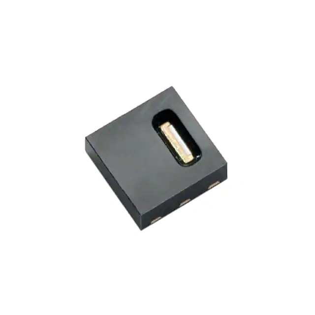
Datasheet SHT21P
Humidity and Temperature Sensor IC
Fully calibrated
Analog output, PWM interface
Low power consumption
Excellent long term stability
DFN type package – reflow solderable
Product Summary
The SHT21 humidity and temperature sensor of Sensirion
has become an industry standard in terms of form factor
and intelligence: Embedded in a reflow solderable Dual
Flat No leads (DFN) package of 3 x 3mm foot print and
1.1mm height it provides calibrated, linearized sensor
signals in analog Pulse Width Modulated (PWM) format.
PWM signal runs on a base frequency of 120Hz, the data
signal is provided on SDA line. Pulling SCL high or low
allows for switching between humidity and temperature,
respectively. The sensor measures twice per second. The
PWM signal may be converted to an analog ratiometric
interface by adding a low pass filter.
The SHT2x sensors contain a capacitive type humidity
sensor, a band gap temperature sensor and specialized
analog and digital integrated circuit – all on a single
CMOSens® chip. This yields in an unmatched sensor
performance in terms of accuracy and stability as well as
minimal power consumption.
Every sensor is individually calibrated and tested. Lot
identification is printed on the sensor.
Dimensions
Sensor Chip
3.0
SHT21P features a generation 4C CMOSens® chip.
Besides the capacitive relative humidity sensor and the
band gap temperature sensor, the chip contains an
amplifier, A/D converter, OTP memory and a digital
processing unit.
3.0
SHT21
P0AC4
0.3 typ
2.4 max
With this set of features and the proven reliability and
long-term stability, the SHT2x sensors offer an
outstanding performance-to-price ratio. For testing SHT2x
two evaluation kits EK-H4 and EK-H5 are available.
1.4 max
1.1
2.2
0.2
0.3
NC
VDD
SCL
0.75
0.4
Bottom
View
Material Contents
While the sensor itself is made of Silicon the sensors’
housing consists of a plated Cu lead-frame and green
epoxy-based mold compound. The device is free of Pb, Cd
and Hg – hence it is fully RoHS and WEEE compliant.
0.4
1.5
2.4
1.0
Additional Information
1.0
NC
VSS
SDA
Figure 1: Drawing of SHT21P sensor package, dimensions
are given in mm (1mm = 0.039inch), tolerances are ±0.1mm.
The die pad (center pad) is internally connected to VSS. The NC
pads must be left floating. Numbering of E/O pads starts at lower
right corner (indicated by notch in die pad) and goes clockwise
(compare Table 2).
www.sensirion.com
Additional information such as Application Notes is
available from the web page www.sensirion.com/sht21.
For more information please contact Sensirion via
info@sensirion.com.
Version 4 – May 2014
1/10
�Sensor Performance
Relative Humidity123
Temperature456
Parameter
Resolution
Condition
12 bit
Value
0.04
Units
%RH
Parameter
Resolution
Condition
14 bit
Value
0.01
Units
°C
Accuracy
tolerance 1
typ
2.0
see Figure 2
%RH
typ
0.3
see Figure 3
°C
%RH
Accuracy
tolerance 1
Repeatability
0.1
%RH
Repeatability
°C
Hysteresis
1
80%RH). For
more details please see Section 1.1 of the Users Guide.
www.sensirion.com
Typical value for operation in normal RH/T operating range. Max. value is <
0.5 %RH/y. Value may be higher in environments with vaporized solvents, outgassing tapes, adhesives, packaging materials, etc. For more details please
refer to Handling Instructions.
5 Values of Supply Current and Power Dissipation are based upon fixed VDD =
3.0V and T = 25°C.
6 Response time depends on heat conductivity of sensor substrate.
7
Max. value is < 0.04°C/y.
Version 4 – May 2014
2/10
�Users Guide SHT21P
1 Extended Specifications
Normal
Range
40
Max.
Range
20
0
-40
-20
0
20
40
60
80
100 120
Temperature (°C)
Figure 4 Operating Conditions
Relative Humidity [%RH]
1.2 RH accuracy at various temperatures
Typical RH accuracy at 25°C is defined in Figure 2. For
other temperatures, typical accuracy has been evaluated
to be as displayed in Figure 5.
100
90
80
70
60
50
40
30
20
10
0
±3.5
±3.5
±3
±3
±2.5
±2.5
±2.5
±2.5
±2.5
±3
±3.5
±3
±3
±2.5
±2.5
±2
±2
±2
±2
±2.5
±3
±3.5
±3
±2.5
±2
±2
±2
±2
±2
±2
±2
±2.5
±3
0
10
20
±3
±2.5
±2
±2
±2
±2
±2
±2
±2
±2.5
±3
±3
±2.5
±2
±2
±2
±2
±2
±2
±2
±2.5
±3
±3
±2.5
±2.5
±2
±2
±2
±2
±2
±2
±2.5
±3
±3.5
±3
±2.5
±2.5
±2
±2
±2
±2
±2
±2.5
±3
30 40 50 60
Temperature [°C]
±4
±3.5
±3
±2.5
±2.5
±2
±2
±2
±2
±2.5
±3
±4
±4
±3.5
±3
±2.5
±2.5
±2
±2
±2
±2.5
±3
70
80
Figure 5 Typical accuracy of relative humidity measurements
given in %RH for temperatures 0 – 80°C.
The solder mask9 design for the land pattern preferably is
of type Non-Solder Mask Defined (NSMD) with solder
mask openings larger than metal pads. For NSMD pads,
the solder mask opening should be about 120μm to
150μm larger than the pad size, providing a 60μm to 75μm
design clearance between the copper pad and solder
mask. Rounded portions of package pads should have a
matching rounded solder mask-opening shape to minimize
the risk of solder bridging. For the actual pad dimensions,
each pad on the PCB should have its own solder mask
opening with a web of solder mask between adjacent
pads.
0.4
0.3
0.2
60
0.4
80
On the PCB the I/O lands8 should be 0.2mm longer than
the package I/O pads. Inward corners may be rounded to
match the I/O pad shape. The I/O land width should match
the DFN-package I/O-pads width 1:1 and the land for the
die pad should match 1:1 with the DFN package – see
Figure 6.
2.4
0.2
100
2.1 Soldering Instructions
The DFN’s die pad (centre pad) and perimeter I/O pads
are fabricated from a planar copper lead-frame by overmolding leaving the die pad and I/O pads exposed for
mechanical and electrical connection. Both the I/O pads
and die pad should be soldered to the PCB. In order to
prevent oxidation and optimize soldering, the bottom side
of the sensor pads is plated with Ni/Pd/Au.
0.7
Relative Humidity (%)
1.1 Operating Range
The sensor works stable within recommended Normal
Range – see Figure 4. Long term exposure to conditions
outside Normal Range, especially at humidity >80%RH,
may temporarily offset the RH signal (+3%RH after 60h).
After return into the Normal Range it will slowly return
towards calibration state by itself. Prolonged exposure to
extreme conditions may accelerate ageing.
2 Application Information
1.5
For details on how Sensirion is specifying and testing
accuracy performance please consult Application Note
“Statement on Sensor Specification”.
1.0
1.0
Figure 6 Recommended metal land pattern for SHT2x. Values
in mm. Die pad (centre pad) may be left floating or be connected
to ground, NC pads shall be left floating. The outer dotted line
represents the outer dimension of the DFN package.
For solder paste printing a laser-cut, stainless steel stencil
with electro-polished trapezoidal walls and with 0.125mm
stencil thickness is recommended. For the I/O pads the
8
The land pattern is understood to be the metal layer on the PCB, onto which
the DFN pads are soldered to.
9 The solder mask is understood to be the insulating layer on top of the PCB
covering the connecting lines.
www.sensirion.com
Version 4 – May 2014
3/10
�Datasheet SHT21P
stencil apertures should be 0.1mm longer than PCB pads
and positioned with 0.1mm offset away from the centre of
the package. The die pad aperture should cover about 70
– 90% of the pad area – say up to 1.4mm x 2.3mm
centered on the thermal land area. It can also be split in
two openings.
Due to the low mounted height of the DFN, “no clean”
type 3 solder paste10 is recommended as well as Nitrogen
purge during reflow.
Temperature
TP
tP
TL
TS (max)
critical zone
It is of great importance to understand that a humidity
sensor is not a normal electronic component and needs to
be handled with care. Chemical vapors at high
concentration in combination with long exposure times
may offset the sensor reading.
For this reason it is recommended to store the sensors in
original packaging including the sealed ESD bag at
following conditions: Temperature shall be in the range of
10°C – 50°C and humidity at 20 – 60%RH (sensors that
are not stored in ESD bags). For sensors that have been
removed from the original packaging we recommend to
store them in ESD bags made of metal-in PE-HD11.
tL
preheating
2.2 Storage Conditions and Handling Instructions
Moisture Sensitivity Level (MSL) is 1, according to
IPC/JEDEC J-STD-020. At the same time, it is
recommended to further process the sensors within 1 year
after date of delivery.
Time
Figure 7 Soldering profile according to JEDEC standard. TP 50°C for 24h to outgas
contaminants before packing.
VDD
SCL
SHT2x
PWM bit stream
C = 100nF
Select RH or T
SDA
VSS
Figure 9 Typical application circuit, including decoupling of
VDD and VSS by a capacitor.
2.8 SDA – Bit Stream Pad
On SDA the sensor is providing PWM output. The signal is
carrying humidity or temperature data depending on SCL
being high or low, respectively. See Table 4 for detailed
I/O characteristic of the sensor.
3 Electrical Characteristics
3.1 Absolute Maximum Ratings
The electrical characteristics of SHT21P are defined in
Table 1. The absolute maximum ratings as given in Table
3 are stress ratings only and give additional information.
Functional operation of the device at these conditions is
not implied. Exposure to absolute maximum rating
conditions for extended periods may affect the sensor
reliability (e.g. hot carrier degradation, oxide breakdown).
www.sensirion.com
Version 4 – May 2014
5/10
�Datasheet SHT21P
Parameter
VDD to VSS
Digital IO Pins (SDA, SCL)
to VSS
Input Current on any Pin
min
-0.3
max
5
Units
V
-0.3
VDD + 0.3
V
-100
100
mA
ESD immunity is qualified according to JEDEC JESD22A114 method (Human Body Model at 4kV), JEDEC
JESD22-A115 method (Machine Model 200V) and ESDA
ESD-STM5.3.1-1999 and AEC-Q100-011 (Charged
Device Model, 750V corner pins, 500V other pins). Latchup immunity is provided at a force current of 100mA with
Tamb = 125°C according to JEDEC JESD78. For exposure
beyond named limits the sensor needs additional
protection circuit.
3.2 Input / Output Characteristics
The electrical characteristics such as power consumption,
low and high level input and output voltages depend on
the supply voltage. For proper communication with the
sensor it is essential to make sure that signal design is
strictly within the limits given in Table 4.
Output Low Voltage, VOL
Output High Voltage, VOH
Output Sink Current, IOL
min
typ
max
Units
40
V
V
µA
0
VDD
tPW
VDD
SDA
Table 3 Electrical absolute maximum ratings
Parameter
tF
0V
Figure 10 PWM signal. Base frequency runs constantly at
approximately 120 Hz, hence tF is about 8.3ms. The signal is
provided on tPW as a ratio of tF.
The measured data – either humidity or temperature – is
provided as ratio of tPW and tF. tPW shall always be given as
ratio of tF to make it independent of variations of the base
frequency.
5 Conversion of Signal Output
Resolution is set to 10 bit relative humidity and 12 bit
temperature reading and cannot be changed. The sensor
reading is linear and hence it can be converted to a
physical value by an easy linear equation.
5.1 Relative Humidity Conversion
With the relative humidity signal output the relative
humidity RH is obtained by the following formula (result in
%RH):
RH 6 125
t PW
tF
Table 4 DC characteristics of output pad. VDD = 2.1 V to 3.6 V,
T = -40 °C to 125 °C, unless otherwise noted.
The physical value RH given above corresponds to
the relative humidity above liquid water according to
World Meteorological Organization (WMO). For
4 Communication with Sensor
relative humidity values above ice RHi the values need to
be transformed as from relative humidity above water RHw
at a certain temperature t follows – compare also
Application Note “Introduction to Humidity”:
4.1 Start up Sensor
As a first step, the sensor is powered up to VDD (between
2.1V and 3.6V). After power-up, the sensor needs at most
150ms for reaching idle state. During that time SDA is in
undefined state. Then the sensor starts measuring and
providing data on PWM bit-stream.
4.2 PWM Specification
Pulse Width Modulation runs on a constant frequency and
the measured information is provided as duty cycle on that
frequency – see Figure 10. Such information is measured
humidity for SCL pulled high and temperature for SCL
pulled low.
β t
β t
RH i RH w exp w exp i
λw t
λi t
Units are %RH for relative humidity and °C for
temperature. The corresponding coefficients are defined
as follows: βw = 17.62, λw = 243.12°C, βi = 22.46, λi =
272.62°C.
5.2 Temperature Conversion
The temperature T is calculated by inserting the ratio of
tPW and tF into the following formula (result in °C):
T 46.85 175.72
www.sensirion.com
Version 4 – May 2014
t PW
tF
6/10
�Datasheet SHT21P
6 Environmental Stability
The SHT2x sensor series were tested based on AECQ100 Rev. G qualification test method where applicable.
Sensor specifications are tested to prevail under the AECQ100 temperature grade 1 test conditions listed in Table
513. Sensor performance under other test conditions
cannot be guaranteed and is not part of the sensor
specifications. Especially, no guarantee can be given for
sensor performance in the field or for customer’s specific
application.
Environment Standard
HTOL
125°C, 408 hours
TC
-50°C - 125°C, 1000 cycles
Results17
Pass
Pass
UHST
130°C / 85%RH / ≈2.3bar, 96h
Pass
THB
85°C / 85%RH, 1000h
Pass
HTSL
150°C, 1000h
Pass
ELFR
125°C, 48h
Pass
ESD immunity HBM 4kV, MM 200V, CDM
Pass
750V/500V (corner/other pins)
Latch-up
force current of ±100mA with Tamb Pass
= 125°C
Table 5: Qualification tests: HTOL = High Temperature
Operating Lifetime, TC = Temperature Cycles, UHST =
Unbiased Highly accelerated Stress Test, THB = Temperature
Humidity Biased, HTSL = High Temperature Storage Lifetime,
ELFR = Early Life Failure Rate. For details on ESD see Sect.
4.1.
If sensors are qualified for reliability and behavior in
extreme conditions, please make sure that they
experience same conditions as the reference sensor. It
should be taken into account that response times in
assemblies may be longer, hence enough dwell time for
the measurement shall be granted. For detailed
information please consult Application Note “Qualification
Guide”.
frame at diced edge is not covered with respective
protective coating. The total weight of the sensor is 25mg.
7.2 Filter Cap and Sockets
For SHT2x a filter cap SF2 is available. It is designed for
fast response times and compact size. Please find the
datasheet on Sensirion’s web page.
For testing of SHT2x sensors sockets, such as from
Plastronics, part number 10LQ50S13030 are
recommended (see e.g. www.locknest.com).
7.3 Traceability Information
All SHT21 are laser marked with an alphanumeric, fivedigit code on the sensor – see Figure 11.
SHT21
P0AC4
Figure 11 Laser marking on sensor. For details see text.
The marking on the sensor consists of two lines with five
digits each. The first line denotes the sensor type
(SHT21). The first digit of the second line defines the
output mode (D = digital, Sensibus and I2C, P = PWM, S =
SDM). The second digit defines the manufacturing year (0
= 2010, 1 = 2011, etc.). The last three digits eventually
represent an alphanumeric tracking code. That code can
be decoded by Sensirion only and allows for tracking on
batch level through production, calibration and testing –
and will be provided upon justified request.
Reels are also labeled, as displayed in Figure 12 and
Figure 13, and give additional traceability information.
Lot No.:
Quantity:
RoHS:
XXO-NN-YRRRTTTTT
RRRR
Compliant
Lot No.
7 Packaging
7.1 Packaging Type
SHT2x sensors are provided in DFN packaging (in
analogy with QFN packaging). DFN stands for Dual Flat
No leads.
The sensor chip is mounted to a lead frame made of Cu
and plated with Ni/Pd/Au. Chip and lead frame are over
molded by green epoxy-based mold compound. Please
note that side walls of sensors are diced and hence lead
Figure 12: First label on reel: XX = Sensor Type (21 for SHT21),
O = Output mode (D = Digital, P = PWM, S = SDM), NN =
product revision no., Y = last digit of year, RRR = number of
sensors on reel divided by 10 (200 for 2000 units), TTTTT =
Traceability Code.
13
Sensor operation temperature range is -40 to 125°C (AEC-Q100 temperature
grade 1).
17 According to accuracy and long term drift specification given on Page 2.
www.sensirion.com
Version 4 – May 2014
7/10
�Datasheet SHT21P
Device Type:
Description:
1-100PPP-NN
Humidity & Temperature Sensor
SHTxx
Part Order No. 1-100PPP-NN or Customer Number
Date of Delivery: DD.MM.YYYY
Order Code:
46CCCC / 0
Figure 13: Second label on reel: For Device Type and Part
Order Number (See Packaging Information on page 2), Delivery
Date (also Date Code) is date of packaging of sensors (DD =
day, MM = month, YYYY = year), CCCC = Sensirion order
number.
7.4 Shipping Package
SHT2x are provided in tape & reel shipment packaging,
sealed into antistatic ESD bags. For SHT21P standard
packaging sizes are 400, 1500 and 5000 units per reel.
Each reel contains 440mm (55 pockets) header tape and
200mm (25 pockets) trailer tape.
0.3
Ø1.5 MIN
Ø1.5 MIN
3.3
5.5
R0.3 MAX
12.0
8.0
2.0
4.0
1.75
The drawing of the packaging tapes with sensor
orientation is shown in Figure 13. The reels are provided in
sealed antistatic bags.
1.3
3.3
0.25
R0.25
Figure 14 Sketch of packaging tape and sensor orientation.
Header tape is to the right and trailer tape to the left on this
sketch.
www.sensirion.com
Version 4 – May 2014
8/10
�Datasheet SHT21P
Revision History
Date
19 Aug 2009
29 Jan 2010
5 May 2010
31 May 2011
December 2011
May 2014
www.sensirion.com
Version
0.6
1.0
1.1
2
3
4
Page(s)
1, 6
1–9
1–9
1 – 4,
6 – 10
Changes
Figure 1 adapted, add details to Section 1.2, 5.1 and Chapter 7
Completely revised version. Require Change Protocol for details.
Elimination of errors and addition of information (ask for change protocol)
Updated temperature accuracy specifications, MSL and standards. Elimination of
errors. For detailed information, please require complete change list at
info@sensirion.com.
1, 7
Minor text adaptations and corrections.
1-4, 7-8 Sensor window dimension updated, several minor adjustments
Version 4 – May 2014
9/10
�Datasheet SHT21P
Warning, Personal Injury
Important Notices
Do not use this product as safety or emergency stop devices or in
any other application where failure of the product could result in
personal injury. Do not use this product for applications other
than its intended and authorized use. Before installing, handling,
using or servicing this product, please consult the data sheet and
application notes. Failure to comply with these instructions could
result in death or serious injury.
If the Buyer shall purchase or use SENSIRION products for any
unintended or unauthorized application, Buyer shall defend, indemnify
and hold harmless SENSIRION and its officers, employees,
subsidiaries, affiliates and distributors against all claims, costs,
damages and expenses, and reasonable attorney fees arising out of,
directly or indirectly, any claim of personal injury or death associated
with such unintended or unauthorized use, even if SENSIRION shall be
allegedly negligent with respect to the design or the manufacture of the
product.
ESD Precautions
The inherent design of this component causes it to be sensitive to
electrostatic discharge (ESD). To prevent ESD-induced damage and/or
degradation, take customary and statutory ESD precautions when
handling this product.
See application note “ESD, Latchup and EMC” for more information.
Warranty
SENSIRION warrants solely to the original purchaser of this product for
a period of 12 months (one year) from the date of delivery that this
product shall be of the quality, material and workmanship defined in
SENSIRION’s published specifications of the product. Within such
period, if proven to be defective, SENSIRION shall repair and/or
replace this product, in SENSIRION’s discretion, free of charge to the
Buyer, provided that:
notice in writing describing the defects shall be given to
SENSIRION within fourteen (14) days after their appearance;
such defects shall be found, to SENSIRION’s reasonable
satisfaction, to have arisen from SENSIRION’s faulty design,
material, or workmanship;
the defective product shall be returned to SENSIRION’s factory at
the Buyer’s expense; and
the warranty period for any repaired or replaced product shall be
limited to the unexpired portion of the original period.
This warranty does not apply to any equipment which has not been
installed and used within the specifications recommended by
SENSIRION for the intended and proper use of the equipment.
EXCEPT FOR THE WARRANTIES EXPRESSLY SET FORTH
HEREIN, SENSIRION MAKES NO WARRANTIES, EITHER EXPRESS
OR IMPLIED, WITH RESPECT TO THE PRODUCT. ANY AND ALL
WARRANTIES, INCLUDING WITHOUT LIMITATION, WARRANTIES
OF MERCHANTABILITY OR FITNESS FOR A PARTICULAR
PURPOSE, ARE EXPRESSLY EXCLUDED AND DECLINED.
SENSIRION is only liable for defects of this product arising under the
conditions of operation provided for in the data sheet and proper use of
the goods. SENSIRION explicitly disclaims all warranties, express or
implied, for any period during which the goods are operated or stored
not in accordance with the technical specifications.
SENSIRION does not assume any liability arising out of any application
or use of any product or circuit and specifically disclaims any and all
liability, including without limitation consequential or incidental
damages. All operating parameters, including without limitation
recommended parameters, must be validated for each customer’s
applications by customer’s technical experts. Recommended
parameters can and do vary in different applications.
SENSIRION reserves the right, without further notice, (i) to change the
product specifications and/or the information in this document and (ii) to
improve reliability, functions and design of this product.
© Copyright 2014 by Sensirion.
CMOSens® is a trademark of Sensirion
All rights reserved
Headquarters and Subsidiaries
SENSIRION AG
Laubisruetistr. 50
CH-8712 Staefa ZH
Switzerland
Sensirion Inc., USA
phone: +1 805 409 4900
info_us@sensirion.com
www.sensirion.com
Sensirion Korea Co. Ltd.
phone: +82 31 337 7700~3
info@sensirion.co.kr
www.sensirion.co.kr
phone: +41 44 306 40 00
fax:
+41 44 306 40 30
info@sensirion.com
www.sensirion.com
Sensirion Japan Co. Ltd.
phone: +81 3 3444 4940
info@sensirion.co.jp
www.sensirion.co.jp
Sensirion China Co. Ltd.
phone: +86 755 8252 1501
info@sensirion.com.cn
www.sensirion.com.cn
Sensirion AG (Germany)
phone: +41 44 927 11 66
info@sensirion.com
www.sensirion.com
To find your local representative, please visit www.sensirion.com/contact
www.sensirion.com
Version 4 – May 2014
10/10
�