LV-MaxSonar® - EZ™ Series
LV-MaxSonar®-EZ™ Series
High Performance Sonar Range Finder
MB1000, MB1010, MB1020, MB1030, MB10402
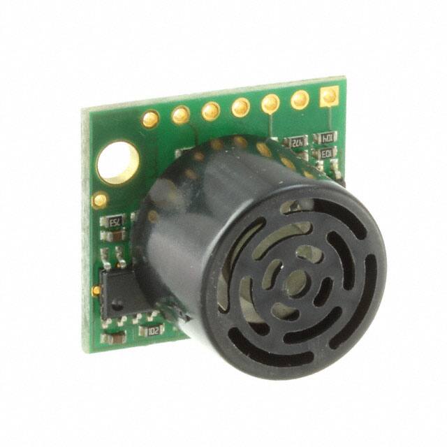
With 2.5V - 5.5V power the LV-MaxSonar-EZ provides very short to long-range
detection and ranging in a very small package. The LV-MaxSonar-EZ detects objects
from 0-inches to 254-inches (6.45-meters) and provides sonar range information from 6inches out to 254-inches with 1-inch resolution. Objects from 0-inches to 6-inches typically range as 6-inches1. The
interface output formats included are pulse width output, analog voltage output, and RS232 serial output. Factory
calibration and testing is completed with a flat object. 1See Close Range Operation
Features
Continuously variable gain for control
and side lobe suppression
Object detection to zero range objects
2.5V to 5.5V supply with 2mA typical
current draw
Readings can occur up to every 50mS,
(20-Hz rate)
Free run operation can continually
measure and output range information
Triggered operation provides the range
reading as desired
Interfaces are active simultaneously
Serial, 0 to Vcc, 9600 Baud, 81N
Analog, (Vcc/512) / inch
Pulse width, (147uS/inch)
Learns ringdown pattern when
commanded to start ranging
Designed for protected indoor
environments
Sensor operates at 42KHz
High output square wave sensor drive
(double Vcc)
Actual operating temperature range from
–40°C to +65°C, Recommended
operating temperature range from 0°C to
+60°C 1
Benefits
Very low cost ultrasonic rangefinder
Reliable and stable range data
Quality beam characteristics
Mounting holes provided on the circuit
board
Very low power ranger, excellent for
multiple sensor or battery-based systems
Fast measurement cycles
Sensor reports the range reading directly
and frees up user processor
Choose one of three sensor outputs
Triggered externally or internally
Applications and Uses
UAV blimps, micro planes and some
helicopters
Bin level measurement
Proximity zone detection
People detection
Robot ranging sensor
Autonomous navigation
Multi-sensor arrays
Distance measuring
Long range object detection
Wide beam sensitivity
Notes:
1
Please reference page 4 for minimum operating
voltage verses temperature information.
2
Please reference page 12 for part number key.
LV-MaxSonar-EZ Mechanical Dimensions
K
Paint Dot Location
Part NumMB1000 MB1010 MB1020 MB1030 MB1040
ber
Paint
Black
Brown
Red
Orange Yellow
Dot Color
J
Close Range Operation
Applications requiring 100% reading-to-reading reliability should not use MaxSonar sensors at a distance closer than
6 inches. Although most users find MaxSonar sensors to work reliably from 0 to 6 inches for detecting objects in many
applications, MaxBotix® Inc. does not guarantee operational reliability for objects closer than the minimum reported
distance. Because of ultrasonic physics, these sensors are unable to achieve 100% reliability at close distances.
_______________________________________________________________________________________________________________________________________
Warning: Personal Safety Applications
We do not recommend or endorse this product be used as a component in any personal safety applications. This product is
not designed, intended or authorized for such use. These sensors and controls do not include the self-checking redundant
circuitry needed for such use. Such unauthorized use may create a failure of the MaxBotix® Inc. product which may result
in personal injury or death. MaxBotix® Inc. will not be held liable for unauthorized use of this component.
MaxBotix® Inc.
Copyright 2005 - 2015 MaxBotix Incorporated
Patent 7,679,996
MaxBotix Inc., products are engineered and assembled in the USA.
Page 1
Web: www.maxbotix.com
PD11832g
�LV-MaxSonar® - EZ™ Series
About Ultrasonic Sensors
Our ultrasonic sensors are in air, non-contact object detection and ranging sensors that detect objects within an area. These
sensors are not affected by the color or other visual characteristics of the detected object. Ultrasonic sensors use high
frequency sound to detect and localize objects in a variety of environments. Ultrasonic sensors measure the time of flight
for sound that has been transmitted to and reflected back from nearby objects. Based upon the time of flight, the sensor
then outputs a range reading.
_______________________________________________________________________________________________________________________________________
Pin Out Description
Pin 1-BW-*Leave open or hold low for serial output on the TX output. When BW pin is held high the TX output sends a
pulse (instead of serial data), suitable for low noise chaining.
Pin 2-PW- This pin outputs a pulse width representation of range. The distance can be calculated using the scale factor of
147uS per inch.
Pin 3-AN- Outputs analog voltage with a scaling factor of (Vcc/512) per inch. A supply of 5V yields ~9.8mV/in. and
3.3V yields ~6.4mV/in. The output is buffered and corresponds to the most recent range data.
Pin 4-RX– This pin is internally pulled high. The LV-MaxSonar-EZ will continually measure range and output if RX
data is left unconnected or held high. If held low the sensor will stop ranging. Bring high for 20uS or more to
command a range reading.
Pin 5-TX- When the *BW is open or held low, the TX output delivers asynchronous serial with an RS232 format, except
voltages are 0-Vcc. The output is an ASCII capital “R”, followed by three ASCII character digits representing the
range in inches up to a maximum of 255, followed by a carriage return (ASCII 13). The baud rate is 9600, 8 bits, no
parity, with one stop bit. Although the voltage of 0-Vcc is outside the RS232 standard, most RS232 devices have
sufficient margin to read 0-Vcc serial data. If standard voltage level RS232 is desired, invert, and connect an RS232
converter such as a MAX232. When BW pin is held high the TX output sends a single pulse, suitable for low noise
chaining. (no serial data)
Pin 6-+5V- Vcc – Operates on 2.5V - 5.5V. Recommended current capability of 3mA for 5V, and 2mA for 3V. Please
reference page 4 for minimum operating voltage verses temperature information.
Pin 7-GND- Return for the DC power supply. GND (& Vcc) must be ripple and noise free for best operation.
_______________________________________________________________________________________________________________________________________
Range “0” Location
Range Zero
The range is measured from the front of the transducer.
The LV-MaxSonar-EZ reports the range to distant targets starting from the front of the sensor as shown in the diagram
below.
In general, the LV-MaxSonar-EZ will report the range to the leading edge of the closest detectable object. Target
detection has been characterized in the sensor beam patterns.
Sensor Minimum Distance
The sensor minimum reported distance is 6-inches (15.2 cm). However, the LV-MaxSonar-EZ will range and report
targets to the front sensor face. Large targets closer than 6-inches will typically range as 6-inches.
_______________________________________________________________________________________________________________________________________
Sensor Operation from 6-inches to 20-inches
Because of acoustic phase effects in the near field, objects between 6-inches and 20-inches may experience acoustic phase
MaxBotix® Inc.
Copyright 2005 - 2015 MaxBotix Incorporated
Patent 7,679,996
MaxBotix Inc., products are engineered and assembled in the USA.
Page 2
Web: www.maxbotix.com
PD11832g
�LV-MaxSonar® - EZ™ Series
cancellation of the returning waveform resulting in inaccuracies of up to 2-inches. These effects become less prevalent as
the target distance increases, and has not been observed past 20-inches.
General Power-Up Instruction
Each time the LV-MaxSonar-EZ is powered up, it will calibrate during its first read cycle. The sensor uses this stored
information to range a close object. It is important that objects not be close to the sensor during this calibration cycle. The
best sensitivity is obtained when the detection area is clear for fourteen inches, but good results are common when clear
for at least seven inches. If an object is too close during the calibration cycle, the sensor may ignore objects at that
distance.
The LV-MaxSonar-EZ does not use the calibration data to temperature compensate for range, but instead to compensate
for the sensor ringdown pattern. If the temperature, humidity, or applied voltage changes during operation, the sensor may
require recalibration to reacquire the ringdown pattern. Unless recalibrated, if the temperature increases, the sensor is
more likely to have false close readings. If the temperature decreases, the sensor is more likely to have reduced up close
sensitivity. To recalibrate the LV-MaxSonar-EZ, cycle power, then command a read cycle.
_______________________________________________________________________________________________________________________________________
Timing Diagram
Timing Description
250mS after power-up, the LV-MaxSonar-EZ is ready to accept the RX command. If the RX pin is left open or held high,
the sensor will first run a calibration cycle (49mS), and then it will take a range reading (49mS). After the power up delay,
the first reading will take an additional ~100mS. Subsequent readings will take 49mS. The LV-MaxSonar-EZ checks the
RX pin at the end of every cycle. Range data can be acquired once every 49mS.
Each 49mS period starts by the RX being high or open, after which the LV-MaxSonar-EZ sends the transmit burst, after
which the pulse width pin (PW) is set high. When a target is detected the PW pin is pulled low. The PW pin is high for up
to 37.5mS if no target is detected. The remainder of the 49mS time (less 4.7mS) is spent adjusting the analog voltage to
the correct level. When a long distance is measured immediately after a short distance reading, the analog voltage may not
reach the exact level within one read cycle. During the last 4.7mS, the serial data is sent.
MaxBotix® Inc.
Copyright 2005 - 2015 MaxBotix Incorporated
Patent 7,679,996
MaxBotix Inc., products are engineered and assembled in the USA.
Page 3
Web: www.maxbotix.com
PD11832g
�LV-MaxSonar® - EZ™ Series
Voltage vs Temperature
The graph below shows minimum operating voltage of the sensor verses temperature.
MaxBotix® Inc.
Copyright 2005 - 2015 MaxBotix Incorporated
Patent 7,679,996
MaxBotix Inc., products are engineered and assembled in the USA.
Page 4
Web: www.maxbotix.com
PD11832g
�LV-MaxSonar® - EZ™ Series
Using Multiple Sensors in a single system
When using multiple ultrasonic sensors in a single system, there can be interference (cross-talk) from the other sensors.
MaxBotix Inc., has engineered and supplied a solution to this problem for the LV-MaxSonar-EZ sensors. The solution is
referred to as chaining. We have 3 methods of chaining that work well to avoid the issue of cross-talk.
The first method is AN Output Commanded Loop. The first sensor will range, then trigger the next sensor to range and so
on for all the sensor in the array. Once the last sensor has ranged, the array stops until the first sensor is triggered to range
again. Below is a diagram on how to set this up.
The next method is AN Output Constantly Looping. The first sensor will range, then trigger the next sensor to range and
so on for all the sensor in the array. Once the last sensor has ranged, it will trigger the first sensor in the array to range
again and will continue this loop indefinitely. Below is a diagram on how to set this up.
The final method is AN Output Simultaneous Operation. This method does not work in all applications and is sensitive to
how the other sensors in the array are positioned in comparison to each other. Testing is recommend to verify this method
will work for your application. All the sensors RX pins are conned together and triggered at the same time causing all the
sensor to take a range reading at the same time. Once the range reading is complete, the sensors stop ranging until
triggered next time. Below is a diagram on how to set this up.
MaxBotix® Inc.
Copyright 2005 - 2015 MaxBotix Incorporated
Patent 7,679,996
MaxBotix Inc., products are engineered and assembled in the USA.
Page 5
Web: www.maxbotix.com
PD11832g
�LV-MaxSonar® - EZ™ Series
Independent Sensor Operation
The LV-MaxSonar-EZ sensors have the capability to operate independently when the user desires. When using the
LV-MaxSonar-EZ sensors in single or independent sensor operation, it is easiest to allow the sensor to free-run. Free-run
is the default mode of operation for all of the MaxBotix Inc., sensors. The LV-MaxSonar-EZ sensors have three separate
outputs that update the range data simultaneously: Analog Voltage, Pulse Width, and RS232 Serial. Below are diagrams
on how to connect the sensor for each of the three outputs when operating in a single or independent sensor operating
environment.
_______________________________________________________________________________________________________________________________________
Selecting an LV-MaxSonar-EZ
Different applications require different sensors. The LV-MaxSonar-EZ product line offers varied sensitivity to allow you
to select the best sensor to meet your needs.
The LV-MaxSonar-EZ Sensors At a Glance
People Detection
Wide Beam
High Sensitivity
MB1000
Large Targets
Narrow Beam
Noise Tolerance
Best Balance
MB1010
MB1020
MB1030
MB1040
The diagram above shows how each product balances sensitivity and noise tolerance. This does not effect the maximum
range, pin outputs, or other operations of the sensor. To view how each sensor will function to different sized targets
reference the LV-MaxSonar-EZ Beam Patterns.
__________________________________________________________________________________________________
Background Information Regarding our Beam Patterns
Each LV-MaxSonar-EZ sensor has a calibrated beam pattern. Each sensor is matched to provide the
approximate detection pattern shown in this datasheet. This allows end users to select the part
number that matches their given sensing application. Each part number has a consistent field of
detection so additional units of the same part number will have similar beam patterns. The beam
plots are provided to help identify an estimated detection zone for an application based on the
acoustic properties of a target versus the plotted beam patterns.
People Sensing:
For users that
desire to detect
people, the
detection area to
the 1-inch
diameter dowel, in
Each beam pattern is a 2D representation of the detection area of the sensor. The beam pattern is
actually shaped like a 3D cone (having the same detection pattern both vertically and horizontally). general, represents
the area that the
Detection patterns for dowels are used to show the beam pattern of each sensor. Dowels are long
cylindered targets of a given diameter. The dowels provide consistent target detection characteristics sensor will
for a given size target which allows easy comparison of one MaxSonar sensor to another MaxSonar reliably detect
people.
sensor.
For each part number, the four patterns (A, B, C, and D) represent the detection zone for a given target size. Each beam
pattern shown is determined by the sensor’s part number and target size.
The actual beam angle changes over the full range. Use the beam pattern for a specific target at any given distance to
calculate the beam angle for that target at the specific distance. Generally, smaller targets are detected over a narrower
beam angle and a shorter distance. Larger targets are detected over a wider beam angle and a longer range.
MaxBotix® Inc.
Copyright 2005 - 2015 MaxBotix Incorporated
Patent 7,679,996
MaxBotix Inc., products are engineered and assembled in the USA.
Page 6
Web: www.maxbotix.com
PD11832g
�LV-MaxSonar® - EZ™ Series
MB1000 LV-MaxSonar-EZ0
The LV-MaxSonar-EZ0 is the highest sensitivity and widest beam sensor of the LV-MaxSonar-EZ sensor series. The
wide beam makes this sensor ideal for a variety of applications including people detection, autonomous navigation, and
wide beam applications.
MB1000 Features and
Benefits
Widest and most sensitive beam
pattern in LV-MaxSonar-EZ line
Low power consumption
Easy to use interface
Will pick up the most noise clutter
when compared to other sensors in
the LV-MaxSonar-EZ line
Detects smaller objects
MaxBotix® Inc.
Copyright 2005 - 2015 MaxBotix Incorporated
Patent 7,679,996
Best sensor to detect soft object in
LV-MaxSonar-EZ line
Requires use of less sensors to
cover a given area
Can be powered by many different
types of power sources
MB1000 Applications and
Uses
Great for people detection
Security
Motion detection
Can detect people up to
Used with battery power
approximately 10 feet
Autonomous navigation
Educational and hobby robotics
Collision avoidance
MaxBotix Inc., products are engineered and assembled in the USA.
Page 7
Web: www.maxbotix.com
PD11832g
�LV-MaxSonar® - EZ™ Series
MB1010 LV-MaxSonar-EZ1
The LV-MaxSonar-EZ1 is the original MaxSonar product. This is our most popular indoor ultrasonic sensor and is a
great low-cost general-purpose sensor for a customer not sure of which LV-MaxSonar-EZ sensor to use.
MB1010 Features and
Benefits
Most popular ultrasonic sensor
Low power consumption
Easy to use interface
Can detect people to 8 feet
Great balance between sensitivity
and object rejection
Can be powered by many different
types of power sources
MaxBotix® Inc.
Copyright 2005 - 2015 MaxBotix Incorporated
Patent 7,679,996
MB1010 Applications and
Uses
Great for people detection
Security
Motion detection
Used with battery power
Autonomous navigation
Educational and hobby robotics
Collision avoidance
MaxBotix Inc., products are engineered and assembled in the USA.
Page 8
Web: www.maxbotix.com
PD11832g
�LV-MaxSonar® - EZ™ Series
MB1020 LV-MaxSonar-EZ2
The LV-MaxSonar-EZ2 is a good compromise between sensitivity and side object rejection. The LV-MaxSonar-EZ2 is an
excellent choice for applications that require slightly less side object detection and sensitivity than the MB1010
LV-MaxSonar-EZ1.
MB1020 Features and
Benefits
Great for applications where the
MB1010 is too sensitive.
Excellent side object rejection
Can be powered by many different
types of power sources
Can detect people up to
MB1020 Applications and
Uses
Landing flying objects
Used with battery power
Autonomous navigation
Educational and hobby robotics
Large object detection
approximately 6 feet
MaxBotix® Inc.
Copyright 2005 - 2015 MaxBotix Incorporated
Patent 7,679,996
MaxBotix Inc., products are engineered and assembled in the USA.
Page 9
Web: www.maxbotix.com
PD11832g
�LV-MaxSonar® - EZ™ Series
MB1030 LV-MaxSonar-EZ3
The LV-MaxSonar-EZ3 is a narrow beam sensor with good side object rejection. The LV-MaxSonar-EZ3 has slightly
wider beam width than theMB1040 LV-MaxSonar-EZ4 which makes it a good choice for when the LV-MaxSonar-EZ4
does not have enough sensitivity for the application.
MB1030 Features and
Benefits
Can detect people up to
approximately 5 feet
MB1030 Applications and
Uses
Excellent side object rejection
Landing flying objects
Low power consumption
Used with battery power
Easy to use interface
Autonomous navigation
Great for when MB1040 is not
Educational and hobby robotics
sensitive enough
Large object detection
Can be powered by many different
types of power sources
MaxBotix® Inc.
Copyright 2005 - 2015 MaxBotix Incorporated
Patent 7,679,996
MaxBotix Inc., products are engineered and assembled in the USA.
Page 10
Web: www.maxbotix.com
PD11832g
�LV-MaxSonar® - EZ™ Series
MB1040 LV-MaxSonar-EZ4
The LV-MaxSonar-EZ4 is the narrowest beam width sensor that is also the least sensitive to side objects offered in
the LV-MaxSonar-EZ sensor line. The LV-MaxSonar-EZ4 is an excellent choice when only larger objects need to be
detected.
MB1040 Features and
Benefits
MB1040 Applications and
Uses
Best side object rejection in the
Landing flying objects
LV-MaxSonar-EZ sensor line
Used with battery power
Low power consumption
Autonomous navigation
Easy to use interface
Educational and hobby robotics
Best for large object detection
Collision avoidance
Can be powered by many different
types of power sources
Can detect people up to
approximately 4 feet
MaxBotix® Inc.
Copyright 2005 - 2015 MaxBotix Incorporated
Patent 7,679,996
MaxBotix Inc., products are engineered and assembled in the USA.
Page 11
Web: www.maxbotix.com
PD11832g
�LV-MaxSonar® - EZ™ Series
Part Numbers
All part numbers are a combination of a six-character base followed by a dash and a three-digit product code.
Please review the following table for more information on the three-digit product code.
M
B
1
0
X
-
0
Base
0
0
0
Housing
Options
Wire
0
Not Applicable
0
No Options (Bagged)
0
No Wire
1
3/4” NPS WR
1
F-Option
1
Wire Attached
2
3/4” NPS WRC
2
P-Option
3
Ultra Compact
3
F-Option and P-Option
4
Ultra Compact Flush Mount
4
No Options (Trayed)
5
1” NPS
5
TTL (Bagged)
6
1” BSPP
6
TTL (Trayed)
7
30MM 1.5
8
Extended Horn
The following table displays all of the active and valid part numbers for this product.
Active Part Numbers for
MB1000, MB1010, MB1020, MB1030, MB1040, MB1060 and MB1061
MB1000-000
MB1010-000
MB1020-000
MB1030-000
MB1040-000
MB1060-000
MB1000-040
MB1010-040
MB1020-040
MB1030-040
MB1040-040
MB1061-000
MaxBotix® Inc.
Copyright 2005 - 2015 MaxBotix Incorporated
Patent 7,679,996
MaxBotix Inc., products are engineered and assembled in the USA.
Page 12
Web: www.maxbotix.com
PD11832g
�LV-MaxSonar® - EZ™ Series
After reviewing this datasheet, do you have any more questions?
We offer Technical Support on all of our products even if you purchased them through one of our many vendors
worldwide.
You can fill out a Technical Support form for assistance on a sensor here --> Technical Support
Not sure which sensor you need for your application?
We offer Sensor Selection Assistance, click the link here to fill out a form for support --> Sensor Selection Help
Looking for tutorials to help you get started?
Frequently Asked Questions about Our Sensors
We receive many questions about our products and services. This resource offers answers to common inquiries
we receive about our product lines and their application.
Fully Calibrated Beam Patterns
All of our sensors are factory calibrated to provide consistent beam patterns, detection zones, to fit into a wide
variety of applications. In our product lines, each model number comes with a different beam pattern that reflects
the sensitivity and the detection zone of how it sees a target. Additionally, we strive to maintain consistency between our finished products, and you will see little to no deviation between sensors of the same model. This allows you to have confidence in your final application when using multiple sensors.
Understanding Range Readings
The success of an application may hinge upon knowing the exact location of a target. However, a sensor may
report one meter even if the target is not exactly one meter away from the sensor. Sensor specifications, such as
resolution, precision, and accuracy, help you to understand sensor performance.
How to Use Multiple Ultrasonic Sensors
This guide covers three ways to run your sensors in a Multiple Sensor environment and issues you may face.
Contact us now with any questions at sales@maxbotix.com or call +1-218-454-0766.
Please call during our preferred business hours of 8:00 am – 4:30 pm EST on Monday through Thursday and 8:00 am –
2:00 pm EST on Friday, or you may leave us a voicemail anytime.
MaxBotix® Inc.
Copyright 2005 - 2015 MaxBotix Incorporated
Patent 7,679,996
MaxBotix Inc., products are engineered and assembled in the USA.
Page 13
Web: www.maxbotix.com
PD11832g
�