Bridgelux Gen 7 V13 Array Series
®
Product Data Sheet DS101
1
�V Series
Introduction
The V Series™ LED Array products deliver high quality light in a compact and cost-effective solid-state lighting package.
These chip on board (CoB) arrays can be efficiently driven at twice the nominal drive current, enabling design flexibility not
previously possible. This high flux density light source is designed to support a wide range of high quality, low cost directional
luminaires and replacement lamps for commercial and residential applications.
The V13 LED Array is available in a variety of electrical, CCT and CRI combinations providing substantial design flexibility and
energy efficiencies.
Lighting system designs incorporating these LED arrays deliver increased system level efficacy and longer service life. Typical
applications include, replacement lamps, and task, accent, spot, track, wide area, security, wall pack and down lights.
Bridgelux Décor Series is our state of the art color line designed specifically for premium applications, producing unmatched
LED light quality with brilliant color-rendering options and offer pleasing and inspiring lighting palettes. Bridgelux Décor
Series color points are available on Vero® SE Series, Vero® Series, V Series™ and H Series™.
Décor Series Class A is based on human response testing, providing color points with a combined GAI and CRI metric.
Décor Series™ Ultra products provide a high CRI of 97 and a minimum R9 value of 93, which emphasizes the reds and color
tones to which the human eye is most receptive - perfect for the most luxurious retail shops and world renowned museums.
Décor Series Ultra is designed as a replacement for halogen lamps.
Décor Series™ Street and Landmark is designed to be a direct replacement for high pressure sodium lamps.
Décor Series™ Showcase is the optimal solution for replacing ceramic metal halide lamps, incorporating the same pure white
light with enhanced spectrum coverage and higher efficacy.
Features
Benefits
• Efficacy of 170 lm/W typical
• Enhanced optical control
• Compact high flux density light source
• Clean white light without pixilation
• Uniform high quality illumination
• High quality true color reproduction
• Minimum 65, 70, 80, 90 and 95 CRI options
• Significantly reduced thermal resistance and
increased operating temperatures
• Streamlined thermal path
• ENERGY STAR® / ANSI compliant color binning
structure with 2, 3 and 4 SDCM options
• Uniform consistent white light
• Lower operating costs
• More energy efficient than incandescent, halogen
and fluorescent lamps
• Easy to use with daylight and motion detectors to
enable increased energy savings
• Low voltage DC operation
• Reduced maintenance costs
• Instant light with unlimited dimming
• Environmentally friendly, no disposal issue
• Vf bin code backside marking
�Contents
Product Feature Map
2
Product Nomenclature
2
Product Selection Guide
3
Performance at Commonly Used Drive Currents
8
Electrical Characteristics
14
Eye Safety
15
Absolute Maximum Ratings
16
Performance Curves
17
Typical Radiation Pattern
20
Typical Color Spectrum
21
Mechanical Dimensions
22
Color Binning Information
23
Packaging and Labeling
24
Design Resources
26
Precautions
26
Disclaimers
26
About Bridgelux
27
1
�Product Feature Map
Bridgelux arrays are fully engineered devices that
provide consistent thermal and optical performance on an
engineered mechanical platform. The V Series arrays are
the most compact chip-on-board devices across all of
Bridgelux’s LED Array products. The arrays incorporate
several features to simplify design integration and
assembly. Please visit www.bridgelux.com for more
information on the V Series family of products.
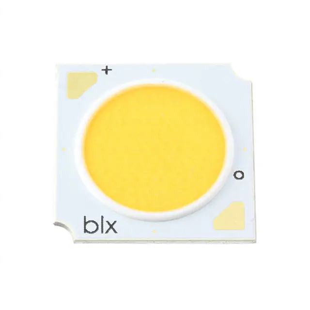
Polarity symbols
Designed to comply with global
safety standards for creepage
and clearance distances
Fully engineered substrate
for consistent thermal, mechanical
and optical properties
White ring around LES
Yellow phosphor Light
Emitting Surface (LES)
Case Temperature (Tc) Measurement Point
Solder Pads
Note: Part number and lot codes are scribed on back of array
Product Nomenclature
The part number designation for Bridgelux V Series LED arrays is explained as follows:
1 2 3 4
5 6 7 8 9 10 11
– 12
– 13 14
BXRE – 30 E 200 0 – C – 7 3
CCT Bin Options
Product Family
Nominal CCT
20 = 2,000K
27 = 2,700K
30 = 3,000K
35 = 3,500K
40 = 4,000K
50 = 5,000K
57 = 5,700K
65 = 6,500K
Gen. 7
2 = 2 SDCM
3 = 3 SDCM
4 = 4 SDCM
Array Configuration
CRI
B = 63 CRI typ.
C = 70 CRI min.
E = 80 CRI min.
G = 90 CRI min.
H = 97 CRI typ.
A = Class A
Color Targeting Designator
0 = Cold Targeted
1 = Hot Targeted
C = Décor Series Showcase Target
Flux Indicator
200x = 2000 lm
2
�Product Selection Guide
The following product configurations are available:
Table 1: Selection Guide, Pulsed Measurement Data (Tj = Tc = 25°C)
Part Number
Nominal
CCT1
(K)
CRI2
Nominal Drive
Current3
(mA)
Typical Pulsed
Flux4,5,6
Tc = 25ºC
(lm)
Minimum
Pulsed Flux6,7
Tc = 25ºC
(lm)
Typical Vf
(V)
Typical
Power
(W)
Typical
Efficacy
(lm/W)
BXRE-17E2000-C-74
1750
80
630
2014
1813
34.8
21.9
92
BXRE-20B2001-B-73
2000
65
450
2455
1992
34.8
15.6
157
157
BXRE-20B2001-C-73
2000
65
630
3437
2853
34.8
21.9
BXRE-25E2000-C-74
2500
80
630
3350
3015
34.8
21.9
153
BXRE-27E2000-B-7x
2700
80
450
2502
2090
34.8
15.6
160
BXRE-27E2000-C-7x
2700
80
630
3503
2926
34.8
21.9
160
BXRE-27G20H0-B-7x
2700
90
450
2142
1928
34.8
15.6
137
BXRE-27G20H0-C-7x
2700
90
630
2999
2699
34.8
21.9
137
BXRE-27G2000-B-7x
2700
90
450
2064
1858
34.8
15.6
132
BXRE-27G2000-C-7x
2700
90
630
2890
2601
34.8
21.9
132
BXRE-27H2000-B-7x
2700
97
450
1830
1647
34.8
15.6
117
BXRE-30C2001-B-74
3000
70
450
2783
2505
34.8
15.6
178
BXRE-30C2001-C-74
3000
70
630
3897
3507
34.8
21.9
178
BXRE-30E2000-B-7x
3000
80
450
2658
2392
34.8
15.6
170
BXRE-30E2000-C-7x
3000
80
630
3722
3350
34.8
21.9
170
BXRE-30G20H0-B-7x
3000
90
450
2252
2027
34.8
15.6
144
BXRE-30G20H0-C-7x
3000
90
630
3153
2837
34.8
21.9
144
BXRE-30G2000-B-7x
3000
90
450
2158
1942
34.8
15.6
138
BXRE-30G2000-C-7x
3000
90
630
3021
2719
34.8
21.9
138
BXRE-30G200C-B-73
3000
90
450
2080
1872
34.8
15.6
133
BXRE-30G200C-C-73
3000
90
630
2912
2621
34.8
21.9
133
BXRE-30A2001-B-738,9
3000
93
450
1939
1745
34.8
15.6
124
BXRE-30A2001-C-738,9
3000
93
630
2715
2443
34.8
21.9
124
BXRE-30H2000-B-7x
3000
97
450
1955
1759
34.8
15.6
125
BXRE-35E2000-B-7x
3500
80
450
2721
2449
34.8
15.6
174
BXRE-35E2000-C-7x
3500
80
630
3809
3428
34.8
21.9
174
BXRE-35G2000-B-7x
3500
90
450
2236
2013
34.8
15.6
143
BXRE-35G2000-C-7x
3500
90
630
3131
2818
34.8
21.9
143
BXRE-35A2001-B-738,9
3500
93
450
2064
1858
34.8
15.6
132
BXRE-35A2001-C-738,9
3500
93
630
2890
2601
34.8
21.9
132
BXRE-40C2001-B-74
4000
70
450
2862
2575
34.8
15.6
183
BXRE-40C2001-C-74
4000
70
630
4006
3606
34.8
21.9
183
BXRE-40E2000-B-7x
4000
80
450
2737
2463
34.8
15.6
175
BXRE-40E2000-C-7x
4000
80
630
3831
3170
34.8
21.9
175
Notes for Table 1:
1. Nominal CCT as defined by ANSI C78.377-2011. Products with a CCT of 5000K-6500K are hot targeted to Tc = 85°C.
2. CRI values are typical for Decor Series Ultra, Décor Series Street and Landmark and Decor Series Class A products. CRI values are minimums for all other
products. Minimum R9 value for 80 CRI products is 0, the minimum R9 values for 90 CRI products is 50, the minimum R9 values for 97 CRI products is 93.
Bridgelux maintains a ± 3 tolerance on R9 values.
3. Drive current is referred to as nominal drive current.
4. Products tested under pulsed condition (10ms pulse width) at nominal test current where Tj (junction temperature) = Tc (case temperature) = 25°C.
5. Typical performance values are provided as a reference only and are not a guarantee of performance.
6. Bridgelux maintains a ±7% tolerance on flux measurements.
7. Minimum flux values at the nominal test current are guaranteed by 100% test.
8. Nominal CCT is defined by the Lighting Research Center’s Class A definition. The center of the Class A color bin is on the corresponding isothermal line.
9. GAI value is 80. To help ensure optimal fixture level performance, GAI is measured at the fixture level, on axis, at a case temperature of 70°C. GAI may vary
depending on fixture design and performance.
3
�Product Selection Guide
The following product configurations are available:
Table 1: Selection Guide, Pulsed Measurement Data (Tj = Tc = 25°C)
Part Number
Nominal
CCT1
(K)
CRI2
Nominal Drive
Current3
(mA)
Typical Pulsed
Flux4,5,6
Tc = 25ºC
(lm)
Minimum
Pulsed Flux6,7
Tc = 25ºC
(lm)
Typical Vf
(V)
Typical
Power
(W)
Typical
Efficacy
(lm/W)
BXRE-40G2000-B-7x
4000
90
450
2283
1938
34.8
15.6
146
BXRE-40G2000-C-7x
4000
90
630
3196
2713
34.8
21.9
146
BXRE-50C2001-B-7x
5000
70
450
2877
2482
34.8
15.6
184
BXRE-50C2001-C-7x
5000
70
630
4028
3475
34.8
21.9
184
177
BXRE-50E2001-B-7x
5000
80
450
2768
2491
34.8
15.6
BXRE-50E2001-C-7x
5000
80
630
3875
3266
34.8
21.9
177
BXRE-50G2001-B-7x
5000
90
450
2393
1986
34.8
15.6
153
BXRE-50G2001-C-7x
5000
90
630
3350
2780
34.8
21.9
153
BXRE-57C2001-B-7x
5700
70
450
2799
2395
34.8
15.6
179
BXRE-57C2001-C-7x
5700
70
630
3919
3353
34.8
21.9
179
BXRE-57E2001-B-7x
5700
80
450
2658
2374
34.8
15.6
170
BXRE-57E2001-C-7x
5700
80
630
3722
3322
34.8
21.9
170
BXRE-65C2001-B-7x
6500
70
450
2799
2439
34.8
15.6
179
BXRE-65C2001-C-7x
6500
70
630
3919
3414
34.8
21.9
179
BXRE-65E2001-B-7x
6500
80
450
2690
2417
34.8
15.6
172
BXRE-65E2001-C-7x
6500
80
630
3766
3383
34.8
21.9
172
Notes for Table 1:
1. Nominal CCT as defined by ANSI C78.377-2011. Products with a CCT of 5000K-6500K are hot targeted to Tc = 85°C.
2. CRI values are typical for Decor Series Ultra, Décor Series Street and Landmark and Decor Series Class A products. CRI values are minimums for all other
products. Minimum R9 value for 80 CRI products is 0, the minimum R9 values for 90 CRI products is 50, the minimum R9 values for 97 CRI products is 93.
Bridgelux maintains a ± 3 tolerance on R9 values.
3. Drive current is referred to as nominal drive current.
4. Products tested under pulsed condition (10ms pulse width) at nominal test current where Tj (junction temperature) = Tc (case temperature) = 25°C.
5. Typical performance values are provided as a reference only and are not a guarantee of performance.
6. Bridgelux maintains a ±7% tolerance on flux measurements.
7. Minimum flux values at the nominal test current are guaranteed by 100% test.
8. Nominal CCT is defined by the Lighting Research Center’s Class A definition. The center of the Class A color bin is on the corresponding isothermal line.
9. GAI value is 80. To help ensure optimal fixture level performance, GAI is measured at the fixture level, on axis, at a case temperature of 70°C. GAI may vary
depending on fixture design and performance.
4
�Product Selection Guide
Table 2: Selection Guide, Stabilized DC Performance (Tc = 70°C) 7,8
Part Number
Nominal
CCT1
(K)
GAI2
CRI3
Nominal
Drive
Current4
(mA)
Typical DC
Flux5,6
Tc = 70ºC
(lm)
Minimum DC
Flux6,9
Tc = 70ºC
(lm)
Typical Vf
(V)
Typical
Power
(W)
Typical
Efficacy
(lm/W)
BXRE-30A2001-B-73
3000
80
93
450
1751
1576
34.4
15.5
113
BXRE-30A2001-C-73
3000
80
93
630
2452
2207
34.4
21.7
113
BXRE-35A2001-B-73
3500
80
93
450
1876
1688
34.4
15.5
121
BXRE-35A2001-C-73
3500
80
93
630
2622
2360
34.4
21.7
121
Notes for Table 2:
1. Nominal CCT is defined by the Lighting Research Center’s Class A definition. The center of the Class A color bin is on the corresponding isothermal line.
2. To help ensure optimal fixture level performance, GAI is measured at the fixture level, on axis, at a case temperature of 70°C. GAI may vary depending on
fixture design and performance.
3. All CRI values are measured at Tj = Tc = 25°C. CRI Values are specified as typical.
4. Drive current is referred to as nominal drive current.
5. Typical performance values are provided as a reference only and are not a guarantee of performance.
6. Bridgelux maintains a ±7% tolerance on flux measurements.
7. Typical stabilized DC performance values are provided as reference only and are not a guarantee of performance.
8. Typical performance is estimated based on operation under DC (direct current) with LED array mounted onto a heat sink with thermal interface material
and the case temperature maintained at specified temperature. Based on Bridgelux test setup, values may vary depending on the thermal design of the
luminaire and/or the exposed environment to which the product is subjected.
9. Minimum flux values at elevated temperatures are provided for reference only and are not guaranteed by 100% production testing. Based on Bridgelux
test setup, values may vary depending on the thermal design of the luminaire and/or the exposed environment to which the product is subjected.
5
�Product Selection Guide
Table 3: Selection Guide, Stabilized DC Performance (Tc = 85°C) 4,5
Part Number
Nominal CCT1
(K)
CRI2
Nominal Drive
Current3
(mA)
Typical DC
Flux4,5
Tc = 85ºC
(lm)
Minimum DC
Flux6
Tc = 85ºC
(lm)
Typical Vf
(V)
Typical
Power
(W)
Typical
Efficacy
(lm/W)
BXRE-17E2000-C-74
1750
80
630
1813
1631
33.9
21.4
85
BXRE-20B2001-B-73
2000
65
450
2210
1989
33.9
15.3
145
BXRE-20B2001-C-73
2000
65
630
3093
2784
33.9
21.4
145
BXRE-25E2000-C-74
2500
80
630
3015
2713
33.9
21.4
141
BXRE-27E2000-B-7x
2700
80
450
2252
2027
33.9
15.3
148
BXRE-27E2000-C-7x
2700
80
630
3153
2837
33.9
21.4
148
BXRE-27G20H0-B-7x
2700
90
450
1928
1735
33.9
15.3
126
BXRE-27G20H0-C-7x
2700
90
630
2699
2429
33.9
21.4
126
BXRE-27G2000-B-7x
2700
90
450
1858
1672
33.9
15.3
122
BXRE-27G2000-C-7x
2700
90
630
2601
2341
33.9
21.4
122
BXRE-27H2000-B-7x
2700
97
450
1647
1482
33.9
15.3
108
BXRE-30C2001-B-74
3000
70
450
2505
2255
33.9
15.3
164
BXRE-30C2001-C-74
3000
70
630
3507
3156
33.9
21.4
164
BXRE-30E2000-B-7x
3000
80
450
2393
2153
33.9
15.3
157
BXRE-30E2000-C-7x
3000
80
630
3350
3015
33.9
21.4
157
BXRE-30G20H0-B-7x
3000
90
450
2027
1824
33.9
15.3
133
BXRE-30G20H0-C-7x
3000
90
630
2837
2554
33.9
21.4
133
BXRE-30G2000-B-7x
3000
90
450
1942
1748
33.9
15.3
127
BXRE-30G2000-C-7x
3000
90
630
2719
2447
33.9
21.4
127
BXRE-30G200C-B-73
3000
90
450
1872
1685
33.9
15.3
123
BXRE-30G200C-C-73
3000
90
630
2621
2358
33.9
21.4
123
BXRE-30A2001-B-738,9
3000
93
450
1745
1571
33.9
15.3
114
BXRE-30A2001-C-738,9
3000
93
630
2443
2199
33.9
21.4
114
BXRE-30H2000-B-7x
3000
97
450
1759
1583
33.9
15.3
115
BXRE-35E2000-B-7x
3500
80
450
2449
2204
33.9
15.3
161
BXRE-35E2000-C-7x
3500
80
630
3428
3086
33.9
21.4
161
BXRE-35G2000-B-7x
3500
90
450
2013
1811
33.9
15.3
132
BXRE-35G2000-C-7x
3500
90
630
2818
2536
33.9
21.4
132
BXRE-35A2001-B-738,9
3500
93
450
1858
1672
33.9
15.3
122
BXRE-35A2001-C-73
3500
93
630
2601
2341
33.9
21.4
122
BXRE-40C2001-B-74
4000
70
450
2575
2318
33.9
15.3
169
BXRE-40C2001-C-74
4000
70
630
3606
3245
33.9
21.4
169
BXRE-40E2000-B-7x
4000
80
450
2463
2217
33.9
15.3
161
8,9
Notes for Table 3:
1. Nominal CCT as defined by ANSI C78.377-2011. Products with a CCT of 5000K-6500K are hot targeted to Tc = 85°C.
2. All CRI values are measured at Tj = Tc = 25°C. CRI values are typical for Decor Series Ultra, Décor Series Street and Landmark and Decor Series Class A
products. CRI values are minimums for all other products. Minimum R9 value for 80 CRI products is 0, the minimum R9 values for 90 CRI products is 50, the
minimum R9 values for 97 CRI products is 93. Bridgelux maintains a ± 3 tolerance on R9 values.
3. Drive current is referred to as nominal drive current.
4. Typical stabilized DC performance values are provided as reference only and are not a guarantee of performance.
5. Typical performance is estimated based on operation under DC (direct current) with LED array mounted onto a heat sink with thermal interface
material and the case temperature maintained at 85°C. Based on Bridgelux test setup, values may vary depending on the thermal design of the
luminaire and/or the exposed environment to which the product is subjected.
6. Minimum flux values at elevated temperatures are provided for reference only and are not guaranteed by 100% production testing. Based on Bridgelux test
setup, values may vary depending on the thermal design of the luminaire and/or the exposed environment to which the product is subjected.
7. Nominal CCT is defined by the Lighting Research Center’s Class A definition. The center of the Class A color bin is on the corresponding isothermal line.
8. GAI value is 80. To help ensure optimal fixture level performance, GAI is measured at the fixture level, on axis, at a case temperature of 70°C. GAI may vary
6
depending on fixture design and performance.
�Product Selection Guide
Table 3: Selection Guide, Stabilized DC Performance (Tc = 85°C) 4,5 (continued)
Part Number
Nominal CCT1
(K)
CRI2
Nominal Drive
Current3
(mA)
BXRE-40E2000-C-7x
4000
80
630
BXRE-40G2000-B-7x
4000
90
450
BXRE-40G2000-C-7x
4000
90
630
BXRE-50C2001-B-7x
5000
70
450
BXRE-50C2001-C-7x
5000
70
630
BXRE-50E2001-B-7x
5000
80
450
BXRE-50E2001-C-7x
5000
80
630
Typical DC
Flux4,5
Tc = 85ºC
(lm)
Minimum DC
Flux6
Tc = 85ºC
(lm)
Typical Vf
(V)
3448
3103
33.9
21.4
161
2055
1849
33.9
15.3
135
2877
2589
33.9
21.4
135
2590
2331
33.9
15.3
170
3625
3263
33.9
21.4
170
2491
2242
33.9
15.3
163
3487
3139
33.9
21.4
163
141
Typical
Power
(W)
Typical
Efficacy
(lm/W)
BXRE-50G2001-B-7x
5000
90
450
2153
1938
33.9
15.3
BXRE-50G2001-C-7x
5000
90
630
3015
2713
33.9
21.4
141
BXRE-57C2001-B-7x
5700
70
450
2519
2267
33.9
15.3
165
BXRE-57C2001-C-7x
5700
70
630
3527
3174
33.9
21.4
165
BXRE-57E2001-B-7x
5700
80
450
2393
2153
33.9
15.3
157
BXRE-57E2001-C-7x
5700
80
630
3350
3015
33.9
21.4
157
BXRE-65C2001-B-7x
6500
70
450
2519
2267
33.9
15.3
165
BXRE-65C2001-C-7x
6500
70
630
3527
3174
33.9
21.4
165
BXRE-65E2001-B-7x
6500
80
450
2421
2179
33.9
15.3
159
BXRE-65E2001-C-7x
6500
80
630
3389
3050
33.9
21.4
159
Notes for Table 3:
1. Nominal CCT as defined by ANSI C78.377-2011. Products with a CCT of 5000K-6500K are hot targeted to Tc = 85°C.
2. All CRI values are measured at Tj = Tc = 25°C. CRI values are typical for Decor Series Ultra, Décor Series Street and Landmark and Decor Series Class A
products. CRI values are minimums for all other products. Minimum R9 value for 80 CRI products is 0, the minimum R9 values for 90 CRI products is 50,
the minimum R9 values for 97 CRI products is 93. Bridgelux maintains a ± 3 tolerance on R9 values.
3. Drive current is referred to as nominal drive current.
4. Typical stabilized DC performance values are provided as reference only and are not a guarantee of performance.
5. Typical performance is estimated based on operation under DC (direct current) with LED array mounted onto a heat sink with thermal interface
material and the case temperature maintained at 85°C. Based on Bridgelux test setup, values may vary depending on the thermal design of the
luminaire and/or the exposed environment to which the product is subjected.
6. Minimum flux values at elevated temperatures are provided for reference only and are not guaranteed by 100% production testing. Based on Bridgelux
test setup, values may vary depending on the thermal design of the luminaire and/or the exposed environment to which the product is subjected.
7. Nominal CCT is defined by the Lighting Research Center’s Class A definition. The center of the Class A color bin is on the corresponding isothermal line.
8. GAI value is 80. To help ensure optimal fixture level performance, GAI is measured at the fixture level, on axis, at a case temperature of 70°C. GAI may
vary depending on fixture design and performance.
7
�Performance at Commonly Used Drive Currents
V Series LED arrays are tested to the specifications shown using the nominal drive currents in Table 1. V Series may also
be driven at other drive currents dependent on specific application design requirements. The performance at any
drive current can be derived from the current vs. voltage characteristics shown in Figures 1 & 2 and the flux vs. current
characteristics shown in Figures 3 & 4. The performance at commonly used drive currents is summarized in Table 4.
Table 4: Product Performance at Commonly Used Drive Currents
Part Number
CRI
BXRE-17E2000-C-74
80
BXRE-20B2001-B-7x
65
BXRE-20B2001-C-73
65
BXRE-25E2000-C-74
80
BXRE-27E2000-B-7x
80
BXRE-27E2000-C-7x
80
BXRE-27G20H0-B-7x
90
BXRE-27G20H0-C-7x
90
Drive
Current1
(mA)
Typical Vf
Tc = 25ºC
(V)
Typical
Power
Tc = 25ºC
(W)
Typical
Flux2
Tc = 25ºC
(lm)
Typical
DC Flux3
Tc = 85ºC
(lm)
Typical
Efficacy
Tc = 25ºC
(lm/W)
158
315
630
945
1260
113
225
450
675
900
158
315
630
945
1260
158
315
630
945
1260
113
225
450
675
900
158
315
630
945
1260
113
225
450
675
900
158
315
630
945
1260
32.3
33.2
34.8
36.1
37.3
32.3
33.2
34.8
36.0
37.2
32.3
33.2
34.8
36.1
37.3
32.3
33.2
34.8
36.1
37.3
32.3
33.2
34.8
36.0
37.2
32.3
33.2
34.8
36.1
37.3
32.3
33.2
34.8
36.0
37.2
32.3
33.2
34.8
36.1
37.3
5.1
10.4
21.9
34.1
47.0
3.6
7.5
15.6
24.3
33.5
5.1
10.4
21.9
34.1
47.0
5.1
10.4
21.9
34.1
47.0
3.6
7.5
15.6
24.3
33.5
5.1
10.4
21.9
34.1
47.0
3.6
7.5
15.6
24.3
33.5
5.1
10.4
21.9
34.1
47.0
548
1057
2014
2894
3693
673
1298
2455
3552
4530
935
1804
3437
4939
6302
911
1758
3350
4813
6142
686
1323
2502
3620
4616
952
1838
3503
5034
6423
587
1133
2142
3100
3953
815
1574
2999
4310
5499
519
996
1813
2707
3442
621
1191
1992
3224
4091
885
1700
2853
4619
5874
863
1657
3015
4501
5724
633
1214
2252
3286
4170
902
1733
3153
4707
5986
542
1040
1928
2813
3570
772
1484
2699
4031
5126
108
101
92
85
79
185
174
157
146
135
184
173
157
145
134
179
168
153
141
131
189
177
160
149
138
187
176
160
148
137
161
152
137
127
118
160
151
137
126
117
Notes for Table 4:
1. Alternate drive currents are provided for reference only and are not a guarantee of performance.
2. Bridgelux maintains a ± 7% tolerance on flux measurements.
3. Typical stabilized DC performance values are provided as reference only and are not a guarantee of performance.
8
�Performance at Commonly Used Drive Currents
Table 4: Product Performance at Commonly Used Drive Currents (Continued)
Part Number
CRI
BXRE-27G2000-B-7x
90
BXRE-27G2000-C-7x
90
BXRE-27H2000-B-7x
97
BXRE-30C2001-B-74
70
BXRE-30C2001-C-74
70
BXRE-30E2000-B-7x
80
BXRE-30E2000-C-7x
80
BXRE-30G20H0-B-7x
90
BXRE-30G20H0-C-7x
90
Drive
Current1
(mA)
Typical Vf
Tc = 25ºC
(V)
Typical
Power
Tc = 25ºC
(W)
Typical
Flux2
Tc = 25ºC
(lm)
Typical
DC Flux3
Tc = 85ºC
(lm)
Typical
Efficacy
Tc = 25ºC
(lm/W)
113
225
450
675
900
158
315
630
945
1260
113
225
450
675
900
113
225
450
675
900
158
315
630
945
1260
113
225
450
675
900
158
315
630
945
1260
113
225
450
675
900
158
315
630
945
1260
32.3
33.2
34.8
36.0
37.2
32.3
33.2
34.8
36.1
37.3
32.3
33.2
34.8
36.0
37.2
32.3
33.2
34.8
36.0
37.2
32.3
33.2
34.8
36.1
37.3
32.3
33.2
34.8
36.0
37.2
32.3
33.2
34.8
36.1
37.3
32.3
33.2
34.8
36.0
37.2
32.3
33.2
34.8
36.1
37.3
3.6
7.5
15.6
24.3
33.5
5.1
10.4
21.9
34.1
47.0
3.6
7.5
15.6
24.3
33.5
3.6
7.5
15.6
24.3
33.5
5.1
10.4
21.9
34.1
47.0
3.6
7.5
15.6
24.3
33.5
5.1
10.4
21.9
34.1
47.0
3.6
7.5
15.6
24.3
33.5
5.1
10.4
21.9
34.1
47.0
566
1092
2064
2987
3809
786
1516
2890
4153
5299
501
968
1830
2647
3376
757
1461
2783
4000
5104
1068
2061
3897
5638
7190
728
1406
2658
3846
4905
1012
1953
3722
5348
6824
617
1191
2252
3258
4155
857
1654
3153
4530
5780
522
1002
1858
2711
3440
744
1429
2601
3884
4939
463
888
1647
2403
3049
717
1377
2505
3741
4757
986
1891
3507
5118
6494
672
1290
2393
3491
4430
958
1841
3350
5002
6360
570
1093
2027
2957
3753
812
1559
2837
4237
5388
156
146
132
123
114
154
145
132
122
113
138
130
117
109
101
208
196
178
164
152
210
197
178
165
153
200
188
170
158
147
199
187
170
157
145
170
160
144
134
124
168
158
144
133
123
Notes for Table 4:
1. Alternate drive currents are provided for reference only and are not a guarantee of performance.
2. Bridgelux maintains a ± 7% tolerance on flux measurements.
3. Typical stabilized DC performance values are provided as reference only and are not a guarantee of performance.
9
�Performance at Commonly Used Drive Currents
Table 4: Product Performance at Commonly Used Drive Currents (Continued)
Part Number
CRI
BXRE-30G2000-B-7x
90
BXRE-30G2000-C-7x
90
BXRE-30G200C-B-73
90
BXRE-30G200C-C-73
90
BXRE-30A2001-B-73
93
BXRE-30A2001-C-73
93
BXRE-30H2000-B-7x
97
BXRE-35E2000-B-7x
80
BXRE-35E2000-C-7x
80
Drive
Current1
(mA)
Typical Vf
Tc = 25ºC
(V)
Typical
Power
Tc = 25ºC
(W)
Typical
Flux2
Tc = 25ºC
(lm)
Typical
DC Flux3
Tc = 85ºC
(lm)
Typical
Efficacy
Tc = 25ºC
(lm/W)
113
225
450
675
900
158
315
630
945
1260
113
225
450
675
900
158
315
630
945
1260
113
225
450
675
900
158
315
630
945
1260
113
225
450
675
900
113
225
450
675
900
158
315
630
945
1260
32.3
33.2
34.8
36.0
37.2
32.3
33.2
34.8
36.1
37.3
32.3
33.2
34.8
36.0
37.2
32.3
33.2
34.8
36.1
37.3
32.3
33.2
34.8
36.0
37.2
32.3
33.2
34.8
36.1
37.3
32.3
33.2
34.8
36.0
37.2
32.3
33.2
34.8
36.0
37.2
32.3
33.2
34.8
36.1
37.3
3.6
7.5
15.6
24.3
33.5
5.1
10.4
21.9
34.1
47.0
3.6
7.5
15.6
24.3
33.5
5.1
10.4
21.9
34.1
47.0
3.6
7.5
15.6
24.3
33.5
5.1
10.4
21.9
34.1
47.0
3.6
7.5
15.6
24.3
33.5
3.6
7.5
15.6
24.3
33.5
5.1
10.4
21.9
34.1
47.0
591
1141
2158
3122
3982
821
1585
3021
4341
5540
570
1100
2080
3009
3837
798
1540
2912
4213
5372
531
1025
1939
2806
3578
744
1436
2715
3928
5009
536
1034
1955
2828
3607
746
1439
2721
3937
5020
1036
1999
3809
5474
6985
546
1047
1942
2834
3596
778
1494
2719
4060
5163
526
1009
1872
2731
3466
736
1413
2621
3824
4852
490
941
1745
2546
3231
687
1317
2443
3565
4524
494
949
1759
2567
3257
688
1320
2449
3573
4534
981
1884
3428
5119
6510
163
153
138
128
119
161
152
138
127
118
157
147
133
124
115
157
147
133
123
114
146
137
124
115
107
146
137
124
115
107
147
139
125
116
108
205
193
174
162
150
203
191
174
160
149
Notes for Table 4:
1. Alternate drive currents are provided for reference only and are not a guarantee of performance.
2. Bridgelux maintains a ± 7% tolerance on flux measurements.
3. Typical stabilized DC performance values are provided as reference only and are not a guarantee of performance.
10
�Performance at Commonly Used Drive Currents
Table 4: Product Performance at Commonly Used Drive Currents (Continued)
Part Number
CRI
BXRE-35G2000-B-7x
90
BXRE-35G2000-C-7x
90
BXRE-35A2001-B-73
93
BXRE-35A2001-C-73
93
BXRE-40C2001-B-74
70
BXRE-40C2001-C-74
70
BXRE-40E2000-B-7x
80
BXRE-40E2000-C-7x
80
BXRE-40G2000-B-7x
90
Drive
Current1
(mA)
Typical Vf
Tc = 25ºC
(V)
Typical
Power
Tc = 25ºC
(W)
Typical
Flux2
Tc = 25ºC
(lm)
Typical
DC Flux3
Tc = 85ºC
(lm)
Typical
Efficacy
Tc = 25ºC
(lm/W)
113
225
450
675
900
158
315
630
945
1260
113
225
450
675
900
158
315
630
945
1260
113
225
450
675
900
158
315
630
945
1260
113
225
450
675
900
158
315
630
945
1260
113
225
450
675
900
32.3
33.2
34.8
36.0
37.2
32.3
33.2
34.8
36.1
37.3
32.3
33.2
34.8
36.0
37.2
32.3
33.2
34.8
36.1
37.3
32.3
33.2
34.8
36.0
37.2
32.3
33.2
34.8
36.1
37.3
32.3
33.2
34.8
36.0
37.2
32.3
33.2
34.8
36.1
37.3
32.3
33.2
34.8
36.0
37.2
3.6
7.5
15.6
24.3
33.5
5.1
10.4
21.9
34.1
47.0
3.6
7.5
15.6
24.3
33.5
5.1
10.4
21.9
34.1
47.0
3.6
7.5
15.6
24.3
33.5
5.1
10.4
21.9
34.1
47.0
3.6
7.5
15.6
24.3
33.5
5.1
10.4
21.9
34.1
47.0
3.6
7.5
15.6
24.3
33.5
613
1183
2236
3235
4126
851
1643
3131
4499
5740
566
1092
2064
2987
3809
786
1516
2890
4153
5299
784
1513
2862
4140
5280
1089
2102
4006
5757
7346
750
1447
2737
3959
5049
1042
2010
3831
5505
7025
626
1207
2283
3303
4213
566
1085
2013
2937
3727
806
1549
2818
4207
5350
522
1002
1858
2711
3440
744
1429
2601
3884
4939
724
1389
2575
3758
4769
1032
1982
3606
5384
6847
692
1328
2463
3594
4560
987
1895
3448
5149
6547
577
1108
2055
2998
3805
169
158
143
133
123
167
157
143
132
122
156
146
132
123
114
154
145
132
122
113
216
203
183
170
158
214
201
183
169
156
206
194
175
163
151
205
192
175
161
149
172
162
146
136
126
Notes for Table 4:
1. Alternate drive currents are provided for reference only and are not a guarantee of performance.
2. Bridgelux maintains a ± 7% tolerance on flux measurements.
3. Typical stabilized DC performance values are provided as reference only and are not a guarantee of performance.
11
�Performance at Commonly Used Drive Currents
Table 4: Product Performance at Commonly Used Drive Currents (Continued)
Part Number
CRI
BXRE-40G2000-C-7x
90
BXRE-50C2001-B-7x
70
BXRE-50C2001-C-7x
70
BXRE-50E2001-B-7x
80
BXRE-50E2001-C-7x
80
BXRE-50G2001-B-7x
90
BXRE-50G2001-C-7x
90
BXRE-57C2001-B-7x
70
BXRE-57C2001-C-7x
70
Drive
Current1
(mA)
Typical Vf
Tc = 25ºC
(V)
Typical
Power
Tc = 25ºC
(W)
Typical
Flux2
Tc = 25ºC
(lm)
Typical
DC Flux3
Tc = 85ºC
(lm)
Typical
Efficacy
Tc = 25ºC
(lm/W)
158
315
630
945
1260
113
225
450
675
900
158
315
630
945
1260
113
225
450
675
900
158
315
630
945
1260
113
225
450
675
900
158
315
630
945
1260
113
225
450
675
900
158
315
630
945
1260
32.3
33.2
34.8
36.1
37.3
32.3
33.2
34.8
36.0
37.2
32.3
33.2
34.8
36.1
37.3
32.3
33.2
34.8
36.0
37.2
32.3
33.2
34.8
36.1
37.3
32.3
33.2
34.8
36.0
37.2
32.3
33.2
34.8
36.1
37.3
32.3
33.2
34.8
36.0
37.2
32.3
33.2
34.8
36.1
37.3
5.1
10.4
21.9
34.1
47.0
3.6
7.5
15.6
24.3
33.5
5.1
10.4
21.9
34.1
47.0
3.6
7.5
15.6
24.3
33.5
5.1
10.4
21.9
34.1
47.0
3.6
7.5
15.6
24.3
33.5
5.1
10.4
21.9
34.1
47.0
3.6
7.5
15.6
24.3
33.5
5.1
10.4
21.9
34.1
47.0
869
1677
3196
4593
5861
788
1522
2877
4163
5309
1095
2114
4028
5789
7386
758
1464
2768
4005
5107
1054
2033
3875
5568
7105
656
1265
2393
3462
4414
911
1758
3350
4813
6142
767
1480
2799
4050
5165
1065
2056
3919
5631
7185
823
1581
2877
4295
5462
728
1396
2590
3779
4795
1037
1993
3625
5414
6884
700
1343
2491
3635
4613
998
1917
3487
5208
6622
605
1161
2153
3142
3987
863
1657
3015
4501
5724
708
1358
2519
3676
4665
1009
1938
3527
5266
6697
171
161
146
135
125
217
204
184
171
159
215
202
184
170
157
209
196
177
165
153
207
195
177
163
151
180
170
153
142
132
179
168
153
141
131
211
198
179
166
154
209
197
179
165
153
Notes for Table 4:
1. Alternate drive currents are provided for reference only and are not a guarantee of performance.
2. Bridgelux maintains a ± 7% tolerance on flux measurements.
3. Typical stabilized DC performance values are provided as reference only and are not a guarantee of performance.
12
�Performance at Commonly Used Drive Currents
Table 4: Product Performance at Commonly Used Drive Currents (Continued)
Part Number
CRI
BXRE-57E2001-B-7x
80
BXRE-57E2001-C-7x
80
BXRE-65C2001-B-7x
70
BXRE-65C2001-C-7x
70
BXRE-65E2001-B-7x
80
BXRE-65E2001-C-7x
80
Drive
Current1
(mA)
Typical Vf
Tc = 25ºC
(V)
Typical
Power
Tc = 25ºC
(W)
Typical
Flux2
Tc = 25ºC
(lm)
Typical
DC Flux3
Tc = 85ºC
(lm)
Typical
Efficacy
Tc = 25ºC
(lm/W)
113
225
450
675
900
158
315
630
945
1260
113
225
450
675
900
158
315
630
945
1260
113
225
450
675
900
158
315
630
945
1260
32.3
33.2
34.8
36.0
37.2
32.3
33.2
34.8
36.1
37.3
32.3
33.2
34.8
36.0
37.2
32.3
33.2
34.8
36.1
37.3
32.3
33.2
34.8
36.0
37.2
32.3
33.2
34.8
36.1
37.3
3.6
7.5
15.6
24.3
33.5
5.1
10.4
21.9
34.1
47.0
3.6
7.5
15.6
24.3
33.5
5.1
10.4
21.9
34.1
47.0
3.6
7.5
15.6
24.3
33.5
5.1
10.4
21.9
34.1
47.0
728
1406
2658
3846
4905
1012
1953
3722
5348
6824
767
1480
2799
4050
5165
1065
2056
3919
5631
7185
737
1422
2690
3892
4963
1024
1976
3766
5411
6904
672
1290
2393
3491
4430
958
1841
3350
5002
6360
708
1358
2519
3676
4665
1009
1938
3527
5266
6697
680
1305
2421
3532
4482
970
1863
3389
5060
6435
200
188
170
158
147
199
187
170
157
145
211
198
179
166
154
209
197
179
165
153
203
191
172
160
148
201
189
172
159
147
Notes for Table 4:
1. Alternate drive currents are provided for reference only and are not a guarantee of performance.
2. Bridgelux maintains a ± 7% tolerance on flux measurements.
3. Typical stabilized DC performance values are provided as reference only and are not a guarantee of performance.
13
�Electrical Characteristics
Table 5: Electrical Characteristics
Forward Voltage
Pulsed, Tc = 25ºC (V) 1, 2, 3, 8
Part Number
Drive Current
(mA)
Typical
Coefficient
of Forward
Voltage4
∆Vf/∆Tc
(mV/ºC)
Typical
Thermal
Resistance
Junction
to Case5,6
Rj-c (ºC/W)
Driver Selection
Voltages7
(V)
Vf Min.
Hot
Tc = 105ºC
(V)
Vf Max.
Cold
Tc = -40ºC
(V)
0.28
31.0
38.3
-14.1
0.34
33.3
40.9
37.4
-14.1
0.20
31.0
38.3
40.1
-14.1
0.24
33.4
41.0
Minimum
Typical
Maximum
450
32.1
34.8
37.4
-14.1
900
34.4
37.2
40.0
630
32.1
34.8
1260
34.5
37.3
BXRE-xxx200x-B-7x
BXRE-xxx200x-C-7x
Notes for Table 5:
1. Parts are tested in pulsed conditions, Tc = 25°C. Pulse width is 10ms.
2. Voltage minimum and maximum are provided for reference only and are not a guarantee of performance.
3. Bridgelux maintains a tester tolerance of ± 0.10V on forward voltage measurements.
4. Typical coefficient of forward voltage tolerance is ± 0.1mV for nominal current.
5. Thermal resistance values are based from test data of a 3000K 80 CRI product.
6. Thermal resistance value was calculated using total electrical input power; optical power was not subtracted from input power. The thermal interface
material used during testing is not included in the thermal resistance value.
7. Vf min hot and max cold values are provided as reference only and are not guaranteed by test. These values are provided to aid in driver design and selection over the operating range of the product.
8. This product has been designed and manufactured per IEC 62031:2014. This product has passed dielectric withstand voltage testing at 1160 V. The working
voltage designated for the insulation is 80V d.c. The maximum allowable voltage across the array must be determined in the end product application.
14
�Eye Safety
Table 6: Eye Safety Risk Group (RG) Classifications
Part Number
BXRE-xxx200x-B-7x
BXRE-xxx200x-C-7x
CCT1,5
Drive
Current 5
(mA)
2700K/3000K
4000K2
5000K3
450
RG1
RG1
RG1
RG1
675
RG1
RG1
RG1
RG2
900
RG1
RG1
RG2
RG2
630
RG1
RG1
RG1
RG1
945
RG1
RG1
RG2
RG2
1260
RG1
RG2
RG2
RG2
6500K4
Notes for Table 6:
1. Eye safety classification for the use of Bridgelux V Series LED arrays is in accordance with specification IEC/TR 62778: Application of IEC 62471 for the
assessment of blue light hazard to light sources and luminaires.
2. For products classified as RG2 at 4000K, Ethr= 1847.5 lx.
3. For products classified as RG2 at 5000K Ethr= 1315.8 lx.
4. For products classified as RG2 at 6500K, Ethr= 1124.5 lx.
5. Please contact your Bridgelux sales representative for Ethr values at specific drive currents and CCTs not listed.
15
�Absolute Maximum Ratings
Table 7: Maximum Ratings
Parameter
Maximum Rating
LED Junction Temperature (Tj)
150°C
Storage Temperature
-40°C to +105°C
Operating Case Temperature1 (Tc)
105°C
Soldering Temperature2
300°C or lower for a maximum of 6 seconds
BXRE-xxx200x-B-7x
BXRE-xxx200x-C-7x
Maximum Drive Current3
900mA
1260mA
Maximum Peak Pulsed Drive Current4
1290mA
1800mA
Maximum Reverse Voltage5
-60V
-60V
Notes for Table 7:
1. For IEC 62717 requirement, please consult your Bridgelux sales representative.
2. Refer to Bridgelux Application Note AN101: Handling and Assembly of Bridgelux V Series LED Arrays
3. Arrays may be driven at higher currents however lumen maintenance may be reduced.
4. Bridgelux recommends a maximum duty cycle of 10% and pulse width of 20 ms when operating LED Arrays at maximum peak pulsed
current specified. Maximum peak pulsed currents indicate values where LED Arrays can be driven without catastrophic failures.
5. Light emitting diodes are not designed to be driven in reverse voltage and will not produce light under this condition. Maximum rating
provided for reference only.
16
�Performance Curves
Figure 1: V13B Drive Current vs. Voltage
Figure 2: V13C Drive Current vs. Voltage
1000
1300
900
1150
700
Forward Current (mA)
Forward Current (mA)
800
600
500
400
300
200
100
0
1000
850
700
550
400
250
32
33
34
35
36
37
100
38
32
33
34
Forward Voltage (V)
36
37
38
Figure 4: V13C Typical Relative Flux vs. Current
Figure 3: V13B Drive Current vs. Voltage
200%
200%
180%
180%
160%
160%
140%
140%
Relative Luminous Flux
Relative Luminous Flux
35
Forward Voltage (V)
120%
100%
80%
60%
120%
100%
80%
60%
40%
40%
20%
20%
0%
0%
0
100
200
300
400
500
600
Forward Current (mA)
700
800
900
1000
100
250
400
550
700
850
1000
1150
1300
Forward Current (mA)
Notes for Figures 1-4:
1. Bridgelux does not recommend driving high power LEDs at low currents. Doing so may produce unpredictable results. Pulse width modulation (PWM) is
recommended for dimming effects.
2. Products tested under pulsed condition (10ms pulse width) at nominal test current where Tj (junction temperature) = Tc (case temperature) = 25°C.
17
�Performance Curves
Figure 5: Typical DC Flux vs. Case Temperature
Figure 6: Typical DC ccy Shift vs. Case Temperature
0
103%
Neutral White
50
75
100
125
0.000
Cool White
25°C Pulsed
97%
-0.003
ccy Shift
Relative Luminous Flux
100%
25
0.003
Warm White
94%
91%
-0.006
-0.009
88%
Warm White
-0.012
85%
-0.015
82%
0
25
50
75
100
125
Case Temperature (°C)
Neutral White
Cool White
25°C Pulsed
Case Temperature (°C)
Figure 7: Typical DC ccx Shift vs. Case Temperature
0
25
50
75
100
125
0.000
-0.002
ccx Shift
-0.004
-0.006
-0.008
Warm White
-0.010
-0.012
Neutral White
Cool White
25°C Pulsed
Case Temperature (°C)
Notes for Figures 5-7:
1. Characteristics shown for warm white based on 3000K and 80 CRI.
2. Characteristics shown for neutral white based on 4000K and 80 CRI.
3. Characteristics shown for cool white based on 5000K and 70 CRI.
4. Characteristics shown for warm white includes Decor Series Class A
5. For other color SKUs, the shift in color will vary. Please contact your Bridgelux Sales Representative for more information.
18
�Performance Curves
Figure 8: 2000K, 65 CRI Color Shift vs. Case Temperature
Figure 9: 3000K, 90 CRI Color Shift vs. Case Temperature1,3
0.403
0.4101
0.41
0.4099
0.4098
15°C
25°C
0.4097
45°C
0.4
45°C
ccy
ccy
Pulsed Center
Point Tc=25°C
25°C
0.401
0.4096
0.4095
65°C
0.399
65°C
0.398
0.4094
85°C
0.4093
0.397
85°C
0.4092
0.526
0.527
0.528
0.529
0.53
0.531
105°C
0.396
105°C
0.4091
0.409
0.525
15°C
0.402
Pulsed Center
Point Tc=25°C
0.395
0.444
0.532
0.4445
0.445
0.4455
0.446
0.4465
0.447
ccx
ccx
Figure 10: 2700K, 97 CRI Color Shift vs. Case Temperature1
Figure 11: 3000K, 97 CRI Color Shift vs. Case Temperature1
0.4110
0.4050
15°C
Pulsed Center
Point
Tc = 25°C
0.4100
25°C
25°C
0.4090
45°C
0.4010
45°C
ccy
ccy
0.4080
Pulsed Center
Point
Tc = 25°C
15°C
0.4030
0.4070
65°C
70°C
0.3990
0.4060
85°C
85°C
0.4050
0.3970
105°C
0.4040
105°C
0.4030
0.457
0.3950
0.4323
0.4572
0.4574
0.4576
0.4578
0.4328
0.4333
0.4343
0.4348
0.4353
ccx
Figure 12: 3000K Class A Color Shift vs. Case Temperature1
Figure 13: 3500K Class A Color Shift vs. Case Temperature1
0.37
0.369
15°C
0.368
25°C
0.367
0.366
15°C
Pulsed
Center Point
Tc=25°C
0.368
25°C
0.366
45°C
Pulsed
Center Point
Tc=25°C
45°C
0.365
ccy
ccy
0.4338
0.458
ccx
0.364
0.364
70°C
0.363
70°C
0.362
85°C
85°C
0.362
0.361
0.36
0.416
0.36
105°C
0.4165
105°C
0.417
ccx
0.4175
0.418
0.4185
0.358
0.392
0.393
0.394
0.395
0.396
0.397
ccx
Note for Figures 8-12:
1. Measurements made under DC test conditions at the nominal drive current.
2. Typical color shift is shown with a tolerance of ±0.002.
3. Characteristics shown for Decor Series Showcase products, BXRE-30G200C-x-73
19
�Typical Radiation Pattern
Figure 13: Typical Spatial Radiation Pattern
Note for Figure 13:
1. Typical viewing angle is 120⁰.
2. The viewing angle is defined as the off axis angle from the centerline where intensity is ½ of the peak value.
Figure 14: Typical Polar Radiation Pattern
20
�Typical Color Spectrum
Figure 15: Typical Color Spectrum
110%
3000K
100%
4000K
5000K
Relative Spectral Power Distribution
90%
6500K
80%
70%
60%
50%
40%
30%
20%
10%
0%
400
450
500
550
600
650
700
750
800
Wavelength (nm)
Note for Figure 15:
1. Color spectra measured at nominal current for Tj = Tc = 25°C.
2. Color spectra shown is 3000K and 80 CRI.
3. Color spectra shown is 4000K and 80 CRI.
4. Color spectra shown is 5000K and 70 CRI.
4. Color spectra shown is 6500K and 70 CRI.
Figure 16: Typical Color Spectrum for Décor Series
1
17E
25E
0.9
20B
27H
30H
0.8
Relative Spectral Power Distribution
30G (Décor Series Showcase)
0.7
0.6
0.5
0.4
0.3
0.2
0.1
0
400
450
500
550
600
Wavelength (nm)
650
700
750
800
Note for Figure 16:
1. Color spectra measured at nominal current for Tj = Tc = 25°C.
21
�Mechanical Dimensions
Figure 17: Drawing for V13 LED Array
Notes for Figure 17:
1. Drawings are not to scale.
2. Drawing dimensions are in millimeters.
3. Unless otherwise specified, tolerances are ±0.1mm.
4. Solder pad labeled “+” denotes positive contact.
5. Refer to Application Notes AN101 for product handling, mounting and heat sink recommendations.
6. The optical center of the LED Array is nominally defined by the mechanical center of the array to a tolerance of ± 0.2mm.
7. Bridgelux maintains a flatness of 0.10mm across the mounting surface of the array.
22
�Color Binning Information
Figure 18: Warm and Neutral White Test Bins in xy Color
Figure 19: Cool White Test Bins in xy Color Space
Space
0.44
0.39
2500K
4SDCM
3 SDCM
4 SDCM
2700K
0.42
4 SDCM
2000K
3SDCM
0.37
3000K
5700K
4000K
0.35
1750K
4SDCM
Y
Y
5000K
0.36
3500K
0.4
3 SDCM
0.38
0.34
0.38
6500K
0.33
0.36
0.32
0.31
0.34
0.36
0.39
0.42
0.45
X
0.48
0.51
0.3
0.54
0.3
0.31
0.32
0.33
0.34
0.35
0.36
X
Note: Pulsed Test Conditions, Tc = 25°C
Table 8: Warm and Neutral White xy Bin Coordinates and Associated Typical CCT
Bin Code
1750K
2000K
2500K
ANSI Bin
(for reference only)
-
-
-
(2580K - 2870K) (2870K - 3220K) (3220K - 3710K) (3710K - 4260K)
73 (3 SDCM)
-
-
-
(2651K - 2794K) (2968K - 3136K) (3369K - 3586K) (3851K - 4130K)
72 (2 SDCM)
-
-
-
(2674K - 2769K) (2995K - 3107K) (3404K - 3548K) (3895K - 4081K)
Center Point (x,y)
(0.5167, 0.336)
(0.5280, 0.4100) (0.4765, 0.4137)
2700K
3000K1
(0.4578, 0.4101)
3500K1
(0.4338, 0.403)
(0.4073, 0.3917)
(0.4465, 0.4024)2
4000K1
(0.3818, 0.3797)
Note for Table 8:
1. Color Binning information excludes Décor Series Class A products. Please contact your Bridgelux Sales Representative for more information.
2. Center Point for Decor Series Showcase.
Table 9: Cool White xy Bin Coordinates and Associated Typical CCT (product is hot targeted to Tc = 85°C)
Bin Code
5000K
5700K
6500K
ANSI Bin (for reference only)
(4745K - 5311K)
(5312K - 6022K)
(6022K - 7042K)
74 (4 SDCM)
(4801K - 5282K)
(5829K - 5481K)
(6270K - 6765K)
73 (3 SDCM)
(4835K - 5215K)
(4590K - 5820K)
(6250K - 6745K)
Center Point (x,y)
(0.3447, 0.3553)
(0.3287, 0.3417)
(0.3123, 0.3282)
23
�Packaging and Labeling
Figure 20: Drawing for V13 Packaging Tray
Notes for Figure 20:
1. Each tube holds 25 V13 COB arrays.
2. One tube is sealed in an anti-static bag. Four bags are placed in a shipping box. Depending on quantities ordered, a bigger shipping box, containing four
boxes may be used to ship products.
3. Each bag and box is to be labeled as shown above.
4. Dimensions for each tube are 21.3 (W) x 9.5(H) x 505 (L). Dimensions for the anti-static bag are 75 (W) x 615 (L) x 3.1 (T) mm. Dimensions for the shipping
box are 58.7 x 13.3 x 7.9 cm.
24
�Packaging and Labeling
Figure 21: Gen. 7 Product Labeling
Bridgelux COB arrays have laser markings on the back side of the substrate to help with product identification. In
addition to the product identification markings, Bridgelux COB arrays also contain markings for internal Bridgelux
manufacturing use only. The image below shows which markings are for customer use and which ones are for
Bridgelux internal use only. The Bridgelux internal manufacturing markings are subject to change without notice,
however these will not impact the form, function or performance of the COB array.
Customer Use- 2D Barcode
Scannable barcode provides
product part number and other
Bridgelux internal production
information.
Customer Use- Product part number
30E4000C 73 2F
Customer Use- Vf Bin Code
included to enable greater
luminaire design flexibility.
Refer to AN92 for bin code
definitions.
25
�Design Resources
Application Notes
3D CAD Models
Bridgelux has developed a comprehensive set of
application notes and design resources to assist
customers in successfully designing with the V Series
product family of LED array products. For all available
application notes visit www.bridgelux.com.
Three dimensional CAD models depicting the product
outline of all Bridgelux V Series LED arrays are available
in both IGS and STEP formats. Please contact your
Bridgelux sales representative for assistance.
Optical Source Models
LM80
Optical source models and ray set files are available
for all Bridgelux products. For a list of available formats,
visit www.bridgelux.com.
LM80 testing has been completed and the LM80 report
is now available. Please contact your Bridgelux sales
representative for LM-80 report.
Precautions
CAUTION: CHEMICAL EXPOSURE HAZARD
Exposure to some chemicals commonly used in
luminaire manufacturing and assembly can cause
damage to the LED array. Please consult Bridgelux
Application Note AN101 for additional information.
CAUTION: RISK OF BURN
Do not touch the V Series LED array during operation.
Allow the array to cool for a sufficient period of time
before handling. The V Series LED array may reach
elevated temperatures such that could burn skin when
touched.
CAUTION
CONTACT WITH LIGHT EMITTING SURFACE (LES)
Avoid any contact with the LES. Do not touch the
LES of the LED array or apply stress to the LES
(yellow phosphor resin area). Contact may cause
damage to the LED array.
Optics and reflectors must not be mounted in contact
with the LES (yellow phosphor resin area).
Disclaimers
MINOR PRODUCT CHANGE POLICY
STANDARD TEST CONDITIONS
The rigorous qualification testing on products offered
by Bridgelux provides performance assurance. Slight
cosmetic changes that do not affect form, fit, or function
may occur as Bridgelux continues product optimization.
Unless otherwise stated, array testing is performed
at the nominal drive current.
26
�About Bridgelux: Bridging Light and Life™
At Bridgelux, we help companies, industries and people experience the power and possibility
of light. Since 2002, we’ve designed LED solutions that are high performing, energy efficient,
cost effective and easy to integrate. Our focus is on light’s impact on human behavior, delivering products that create better environments, experiences and returns—both experiential and
financial. And our patented technology drives new platforms for commercial and industrial
luminaires.
For more information about the company, please visit
bridgelux.com
twitter.com/Bridgelux
facebook.com/Bridgelux
youtube.com/user/Bridgelux
linkedin.com/company/bridgelux-inc-_2
WeChat ID: BridgeluxInChina
46430 Fremont Boulevard
Fremont, CA 94538 U.S.A.
Tel (925) 583-8400
www.bridgelux.com
© 2016-2019 Bridgelux, Inc. All rights reserved. Product specifications are subject to change without notice. Bridgelux, the Bridgelux stylized logo design, Vero,
V Series and V Series HD are registered trademarks, and Decor Series is a trademark of Bridgelux, Inc. All other trademarks are the property of their respective owners.
Bridgelux Gen 7 V13 Array Series Product Data Sheet DS101 Rev. N (07/2019)
27
�