Bridgelux Vero SE 13 Array
®
®
Product Data Sheet DS121
1
�Vero SE
Introduction
Vero® SE Series is a revolutionary light source system that integrates Bridgelux’s seventh generation COB technology with
poke-in connectivity enabling solder-free installation. Vero SE LED light sources streamline assembly processes, lower
manufacturing cost, simplify luminaire design, improve light quality and increase design flexibility.
Vero SE is available in four different light emitting surface (LES) configurations that operate reliably over a broad current
range. With Vero SE, secondary connector and holder components are not required, allowing for rapid integration of arrays
into fixtures and an efficient field replaceable solution. Vero SE arrays deliver increased lumen density for improved beam
control and precision lighting with 2 and 3 SDCM color control standards for clean and consistent uniform lighting.
Bridgelux Décor Series is our state of the art color line designed specifically for premium applications, producing unmatched
LED light quality with brilliant color-rendering options and offer pleasing and inspiring lighting palettes. Bridgelux Décor
Series color points are available on Vero® SE Series, Vero® Series, V Series™ and V Series™ HD.
Décor Series Class A is based on human response testing, providing color points with a combined GAI and CRI metric.
Décor Series™ Ultra products provide a high CRI of 97 and a minimum R9 value of 93, which emphasizes the reds and color
tones to which the human eye is most receptive - perfect for the most luxurious retail shops and world renowned museums.
Décor Series Ultra is also a good replacement for halogen lamps.
Décor Series™ Showcase is the optimal solution for replacing ceramic metal halide lamps, incorporating the same pure white
light with enhanced spectrum coverage and higher efficacy.
Features
• Poke-in connectivity
• Efficacy of 157 lm/W typical
• Lumen output performance ranges from
511 to 6,931 lumens
Benefits
• Poke-in connectivity enables solderless, connector
free installation
• Broad application coverage for interior and
exterior lighting
• Broad range of CCT options from 2700K to 6500K
• Flexibility for application driven lighting design
requirements
• CRI options; minimum 70, 80, and 90
• High quality, true color reproduction
• Color control: 2 and 3 SDCM for 2700K-4000K CCT
• Uniform consistent white light
• Reliable operation at up to 2X nominal drive current
• Flexibility in design optimization
• Radial die pattern and improved lumen density
• Enhanced ease of use and assembly
• Top side part number markings
• Ability to configure multiple Vero SE arrays in series
and parallel reduces customer driver cost
• No exposed solder pads or electrical connections
• Vf bin code backside marking
• Improved inventory management and
quality control
�Contents
Product Feature Map
2
Product Nomenclature
2
Product Selection Guide
3
Performance at Commonly Used Drive Currents
10
Electrical Characteristics
19
Eye Safety
20
Absolute Maximum Ratings
21
Performance Curves
22
Typical Radiation Pattern
25
Typical Color Spectrum
26
Mechanical Dimensions
27
Color Binning Information
28
Packaging and Labeling
29
Design Resources
31
Precautions
31
Disclaimers
31
About Bridgelux
32
1
�Product Feature Map
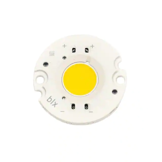
Vero SE 13 is the second smallest form factor in the
product family of the next generation solid state light
sources. In addition to delivering the performance and
light quality required for many lighting applications,
Vero SE incorporates several features to simplify the
design integration and manufacturing process, accelerate
time to market and reduce system costs. Please visit www.
bridgelux.com for more information on the Vero SE family
of products.
2D Bar code provides full
manufacturing traceability
Polarity indication marks simplify
manufacturing operator instructions
Wire release mechanisms x4
Tc Measurement point
Optic mounting holes
Radial die configuration improves lumen
density and beam control
Mounting holes
Top side part number marking improves
inventory management and outgoing
quality control
Zhaga Book 3 compatible
mounting locations
Test ports for probing
Dual poke-in connectivity
Product Nomenclature
The part number designation for Bridgelux Vero SE LED arrays is explained as follows:
1 2 3 4
–
5 6 7 8 9 10 11
– 12
– 13 14
– 15 16
BXRC – 30 E 200 0 – C – 7 3 – SE
Product Family
Nominal CCT
27 = 2,700K
30 = 3,000K
35 = 3,500K
40 = 4,000K
50 = 5,000K
57 = 5,700K
65 = 6,500K
Special Edition
CCT Bin Options
Gen. 7
Array Configuration
CRI
C = 70 CRI min.
E = 80 CRI min.
G = 90 CRI min.
H = 97 CRI typ.
A = Class A
2 = 2 SDCM
3 = 3 SDCM
4 = 4 SDCM
Color Targeting Designator
0 = Cold Targeted
1 = Hot Targeted
C = Decor Series Showcase
Flux Indicator
200x = 2000 lm
2
�Product Selection Guide
The following product configurations are available:
Table 1: Selection Guide, Pulsed Measurement Data (Tj = Tc = 25°C)
Part Number
Nominal
CCT1
(K)
CRI2
Nominal Drive
Current3
(mA)
Typical Pulsed
Flux4,5,6
Tc = 25ºC
(lm)
Minimum
Pulsed Flux6,7
Tc = 25ºC
(lm)
Typical Vf
(V)
Typical
Power
(W)
Typical
Efficacy
(lm/W)
BXRC-27E2000-B-7X-SE
2700
80
450
2365
2128
34.8
15.7
151
BXRC-27E2000-C-7X-SE
2700
80
630
3311
2979
34.8
21.9
151
BXRC-27E2000-D-7X-SE
2700
80
500
2401
2161
31.8
15.9
151
BXRC-27G20H0-B-7X-SE
2700
90
450
2036
1832
34.8
15.7
130
BXRC-27G20H0-C-7X-SE
2700
90
630
2850
2565
34.8
21.9
130
BXRC-27G20H0-D-7X-SE
2700
90
500
2067
1860
31.8
15.9
130
BXRC-27G2000-B-7X-SE
2700
90
450
1973
1776
34.8
15.7
126
BXRC-27G2000-C-7X-SE
2700
90
630
2762
2486
34.8
21.9
126
BXRC-27G2000-D-7X-SE
2700
90
500
2003
1803
31.8
15.9
126
BXRC-27H2000-B-7x-SE
2700
97
450
1707
1536
34.8
15.7
109
BXRC-27H2000-C-7x-SE
2700
97
630
2390
2151
34.8
21.9
109
BXRC-27H2000-D-7x-SE
2700
97
500
1733
1560
31.8
15.9
109
BXRC-30C2001-B-7X-SE
3000
70
450
2694
2424
34.8
15.7
172
BXRC-30C2001-C-7X-SE
3000
70
630
3771
3394
34.8
21.9
172
BXRC-30C2001-D-7X-SE
3000
70
500
2735
2461
31.8
15.9
172
BXRC-30E2000-B-7X-SE
3000
80
450
2459
2213
34.8
15.7
157
BXRC-30E2000-C-7X-SE
3000
80
630
3442
3098
34.8
21.9
157
BXRC-30E2000-D-7X-SE
3000
80
500
2496
2247
31.8
15.9
157
BXRC-30G20H0-B-7X-SE
3000
90
450
2145
1931
34.8
15.7
137
BXRC-30G20H0-C-7X-SE
3000
90
630
3004
2703
34.8
21.9
137
BXRC-30G20H0-C-7X-SE
3000
90
500
2178
1960
31.8
15.9
137
BXRC-30G2000-B-7X-SE
3000
90
450
2051
1846
34.8
15.7
131
BXRC-30G2000-C-7X-SE
3000
90
630
2872
2585
34.8
21.9
131
BXRC-30G2000-D-7X-SE
3000
90
500
2083
1875
31.8
15.9
131
BXRC-30G200C-B-73-SE
3000
90
450
1906
34.8
15.8
121
BXRC-30G200C-D-73-SE
3000
90
500
1924
1732
31.8
15.9
121
BXRC-30H2000-B-7x-SE
3000
97
450
1832
1649
34.8
15.7
117
117
BXRC-30H2000-C-7x-SE
3000
97
630
2565
2309
34.8
21.9
BXRC-30H2000-D-7x-SE
3000
97
500
1860
1674
31.8
15.9
117
BXRC-30A2001-B-73-SE8,9
3000
93
450
1848
1663
34.8
15.7
118
BXRC-30A2001-C-73-SE8,9
3000
93
630
2587
2328
34.8
21.9
118
BXRC-30A2001-D-73-SE
3000
93
500
1876
1689
31.8
15.9
118
8,9
Notes for Table 1:
1. Nominal CCT as defined by ANSI C78.377-2011. Products with a CCT of 5000K-6500K are hot targeted to Tc = 85°C.
2. CRI values are typical for Decor Series Ultra, Decor Series Street and Landmark and Decor Series Class A products. CRI values are minimums for all other
products. Minimum R9 value for 80 CRI products is 0, the minimum R9 value for 90 CRI products is 50, the minimum R9 value for 97 CRI products is 93.
Bridgelux maintains a ± 3 tolerance on CRI and R9 values.
3. Drive current is referred to as nominal drive current.
4. Products tested under pulsed condition (10ms pulse width) at nominal test current where Tj (junction temperature) = Tc (case temperature) = 25°C.
5. Typical performance values are provided as a reference only and are not a guarantee of performance.
6. Bridgelux maintains a ±7% tolerance on flux measurements.
7. Minimum flux values at the nominal test current are guaranteed by 100% test.
8. Nominal CCT is defined by the Lighting Research Center’s Class A definition. The center of the Class A color bin is on the corresponding isothermal line.
9. GAI value is 80. To help ensure optimal fixture level performance, GAI is measured at the fixture level, on axis, at a case temperature of 70°C. GAI may vary
depending on fixture design and performance.
3
�Product Selection Guide
Table 1: Selection Guide, Pulsed Measurement Data (Tj = Tc = 25°C) (continued)
Part Number
Nominal
CCT1
(K)
CRI
2
Nominal Drive
Current3
(mA)
Typical Pulsed
Flux4,5,6
Tc = 25ºC
(lm)
Minimum
Pulsed Flux6,7
Tc = 25ºC
(lm)
Typical Vf
(V)
Typical
Power
(W)
Typical
Efficacy
(lm/W)
BXRC-35E2000-B-7X-SE
3500
80
450
2537
2283
34.8
15.7
162
BXRC-35E2000-C-7X-SE
3500
80
630
3552
3197
34.8
21.9
162
BXRC-35E2000-D-7X-SE
3500
80
500
2576
2318
31.8
15.9
162
BXRC-35G2000-B-7X-SE
3500
90
450
2114
1903
34.8
15.7
135
BXRC-35G2000-C-7X-SE
3500
90
630
2960
2664
34.8
21.9
135
BXRC-35G2000-D-7X-SE
3500
90
500
2147
1932
31.8
15.9
135
BXRC-35A2001-B-73-SE8,9
3500
93
450
1989
1790
34.8
15.7
127
BXRC-35A2001-C-73-SE8,9
3500
93
630
2784
2506
34.8
21.9
127
BXRC-35A2001-D-73-SE8,9
3500
93
500
2019
1817
31.8
15.9
127
BXRC-40C2001-B-7X-SE
4000
70
450
2772
2495
34.8
15.7
177
177
BXRC-40C2001-C-7X-SE
4000
70
630
3881
3492
34.8
21.9
BXRC-40C2001-D-7X-SE
4000
70
500
2814
2533
31.8
15.9
177
BXRC-40E2000-B-7X-SE
4000
80
450
2553
2297
34.8
15.7
163
163
BXRC-40E2000-C-7X-SE
4000
80
630
3574
3216
34.8
21.9
BXRC-40E2000-D-7X-SE
4000
80
500
2592
2333
31.8
15.9
163
BXRC-40G2000-B-7X-SE
4000
90
450
2192
1973
34.8
15.7
140
BXRC-40G2000-C-7X-SE
4000
90
630
3069
2762
34.8
21.9
140
BXRC-40G2000-D-7X-SE
4000
90
500
2226
2003
31.8
15.9
140
BXRC-40H2000-B-7X-SE
4000
97
450
1864
1677
34.8
15.7
119
BXRC-40H2000-C-7X-SE
4000
97
630
2609
2348
34.8
21.9
119
BXRC-40H2000-D-7X-SE
4000
97
500
1892
1703
31.8
15.9
119
BXRC-40A2001-B-73-SE8,9
4000
93
450
2130
1917
34.8
15.7
136
BXRC-40A2001-C-73-SE8,9
4000
93
630
2982
2683
34.8
21.9
136
BXRC-40A2001-D-73-SE8,9
4000
93
500
2162
1946
31.8
15.9
136
BXRC-50C2001-B-74-SE
5000
70
450
2803
2523
34.8
15.7
179
BXRC-50C2001-C-74-SE
5000
70
630
3924
3532
34.8
21.9
179
BXRC-50C2001-D-74-SE
5000
70
500
2846
2561
31.8
15.9
179
BXRC-50E2001-B-74-SE
5000
80
450
2631
2368
34.8
15.7
168
BXRC-50E2001-C-74-SE
5000
80
630
3683
3315
34.8
21.9
168
BXRC-50E2001-D-74-SE
5000
80
500
2671
2404
31.8
15.9
168
BXRC-50G2001-B-74-SE
5000
90
450
2239
2015
34.8
15.7
143
BXRC-50G2001-C-74-SE
5000
90
630
3135
2822
34.8
21.9
143
BXRC-50G2001-D-74-SE
5000
90
500
2274
2046
31.8
15.9
143
Notes for Table 1:
1. Nominal CCT as defined by ANSI C78.377-2011. Products with a CCT of 5000K-6500K are hot targeted to Tc = 85°C.
2. CRI values are typical for Decor Series Ultra, Decor Series Street and Landmark and Decor Series Class A products. CRI values are minimums for all other
products. Minimum R9 value for 80 CRI products is 0, the minimum R9 value for 90 CRI products is 50, the minimum R9 value for 97 CRI products is 93.
Bridgelux maintains a ± 3 tolerance on CRI and R9 values.
3. Drive current is referred to as nominal drive current.
4. Products tested under pulsed condition (10ms pulse width) at nominal test current where Tj (junction temperature) = Tc (case temperature) = 25°C.
5. Typical performance values are provided as a reference only and are not a guarantee of performance.
6. Bridgelux maintains a ±7% tolerance on flux measurements.
7. Minimum flux values at the nominal test current are guaranteed by 100% test.
8. Nominal CCT is defined by the Lighting Research Center’s Class A definition. The center of the Class A color bin is on the corresponding isothermal line.
9. GAI value is 80. To help ensure optimal fixture level performance, GAI is measured at the fixture level, on axis, at a case temperature of 70°C. GAI may vary
depending on fixture design and performance.
4
�Product Selection Guide
Table 1: Selection Guide, Pulsed Measurement Data (Tj = Tc = 25°C) (continued)
Part Number
Nominal
CCT1
(K)
CRI
2
Nominal Drive
Current3
(mA)
Typical Pulsed
Flux4,5,6
Tc = 25ºC
(lm)
Minimum
Pulsed Flux6,7
Tc = 25ºC
(lm)
Typical Vf
(V)
Typical
Power
(W)
Typical
Efficacy
(lm/W)
BXRC-57C2001-B-74-SE
5700
70
450
2709
2438
34.8
15.7
173
BXRC-57C2001-C-74-SE
5700
70
630
3793
3414
34.8
21.9
173
BXRC-57C2001-D-74-SE
5700
70
500
2751
2476
31.8
15.9
173
BXRC-57E2001-B-74-SE
5700
80
450
2600
2340
34.8
15.7
166
BXRC-57E2001-C-74-SE
5700
80
630
3639
3275
34.8
21.9
166
BXRC-57E2001-D-74-SE
5700
80
500
2639
2375
31.8
15.9
166
BXRC-65C2001-B-74-SE
6500
70
450
2756
2481
34.8
15.7
176
BXRC-65C2001-C-74-SE
6500
70
630
3859
3473
34.8
21.9
176
BXRC-65C2001-D-74-SE
6500
70
500
2798
2519
31.8
15.9
176
BXRC-65E2001-B-74-SE
6500
80
450
2647
2382
34.8
15.7
169
BXRC-65E2001-C-74-SE
6500
80
630
3705
3335
34.8
21.9
169
BXRC-65E2001-D-74-SE
6500
80
500
2687
2418
31.8
15.9
169
Notes for Table 1:
1. Nominal CCT as defined by ANSI C78.377-2011. Products with a CCT of 5000K-6500K are hot targeted to Tc = 85°C.
2. CRI values are typical for Decor Series Ultra, Decor Series Street and Landmark and Decor Series Class A products. CRI values are minimums for all other
products. Minimum R9 value for 80 CRI products is 0, the minimum R9 value for 90 CRI products is 50, the minimum R9 value for 97 CRI products is 93.
Bridgelux maintains a ± 3 tolerance on CRI and R9 values.
3. Drive current is referred to as nominal drive current.
4. Products tested under pulsed condition (10ms pulse width) at nominal test current where Tj (junction temperature) = Tc (case temperature) = 25°C.
5. Typical performance values are provided as a reference only and are not a guarantee of performance.
6. Bridgelux maintains a ±7% tolerance on flux measurements.
7. Minimum flux values at the nominal test current are guaranteed by 100% test.
8. Nominal CCT is defined by the Lighting Research Center’s Class A definition. The center of the Class A color bin is on the corresponding isothermal line.
9. GAI value is 80. To help ensure optimal fixture level performance, GAI is measured at the fixture level, on axis, at a case temperature of 70°C. GAI may vary
depending on fixture design and performance.
5
�Product Selection Guide
Table 2: Selection Guide, Stabilized DC Performance (Tc = 70°C) 7,8
Part Number
Nominal
CCT1
(K)
GAI2
CRI3
Nominal
Drive
Current4
(mA)
Typical DC
Flux5,6
Tc = 70ºC
(lm)
Minimum DC
Flux6,9
Tc = 70ºC
(lm)
Typical Vf
(V)
Typical
Power
(W)
Typical
Efficacy
(lm/W)
BXRC-30A2001-B-73
3000
80
93
450
1719
1512
34.4
15.5
111
BXRC-30A2001-C-73
3000
80
93
630
2406
2117
34.4
21.6
111
BXRC-30A2001-D-73
3000
80
93
500
1745
1535
31.2
15.6
112
BXRC-35A2001-B-73
3500
80
93
450
1850
1628
34.4
15.5
120
BXRC-35A2001-C-73
3500
80
93
630
2589
2279
34.4
21.6
120
BXRC-35A2001-D-73
3500
80
93
500
1878
1653
31.2
15.6
120
BXRC-40A2001-B-73
4000
80
93
450
1981
1743
34.4
15.5
128
BXRC-40A2001-C-73
4000
80
93
630
2773
2440
34.4
21.6
128
BXRC-40A2001-D-73
4000
80
93
500
2011
1770
31.2
15.6
129
Notes for Table 2:
1. Nominal CCT is defined by the Lighting Research Center’s Class A definition. The center of the Class A color bin is on the corresponding isothermal line.
2. To help ensure optimal fixture level performance, GAI is measured at the fixture level, on axis, at a case temperature of 70°C. GAI may vary depending on
fixture design and performance.
3. CRI Values are specified as typical.
4. Drive current is referred to as nominal drive current.
5. Typical performance values are provided as a reference only and are not a guarantee of performance.
6. Bridgelux maintains a ±7% tolerance on flux measurements.
7. Typical stabilized DC performance values are provided as reference only and are not a guarantee of performance.
8. Typical performance is estimated based on operation under DC (direct current) with LED array mounted onto a heat sink with thermal interface material
and the case temperature maintained at specified temperature. Based on Bridgelux test setup, values may vary depending on the thermal design of the
luminaire and/or the exposed environment to which the product is subjected.
9. Minimum flux values at elevated temperatures are provided for reference only and are not guaranteed by 100% production testing. Based on Bridgelux
test setup, values may vary depending on the thermal design of the luminaire and/or the exposed environment to which the product is subjected
6
�Product Selection Guide
Table 3: Selection Guide, Stabilized DC Performance (Tc = 85°C) 4,5
Part Number
Nominal CCT1
(K)
CRI2
Nominal Drive
Current3
(mA)
Typical DC
Flux4,5
Tc = 85ºC
(lm)
Minimum DC
Flux6
Tc = 85ºC
(lm)
Typical Vf
(V)
Typical
Power
(W)
Typical
Efficacy
(lm/W)
139
BXRC-27E2000-B-7X-SE
2700
80
450
2128
1915
33.9
15.3
BXRC-27E2000-C-7X-SE
2700
80
630
2979
2682
33.9
21.4
139
BXRC-27E2000-D-7X-SE
2700
80
500
2161
1945
30.9
15.5
140
BXRC-27G20H0-B-7X-SE
2700
90
450
1832
1649
33.9
15.3
120
BXRC-27G20H0-C-7X-SE
2700
90
630
2565
2309
33.9
21.4
120
BXRC-27G20H0-D-7X-SE
2700
90
500
1860
1674
30.9
15.5
120
BXRC-27G2000-B-7X-SE
2700
90
450
1776
1598
33.9
15.3
116
BXRC-27G2000-C-7X-SE
2700
90
630
2486
2238
33.9
21.4
116
BXRC-27G2000-D-7X-SE
2700
90
500
1803
1623
30.9
15.5
117
BXRC-27H2000-B-7x-SE
2700
97
450
1536
1383
33.9
15.3
101
BXRC-27H2000-C-7x-SE
2700
97
630
2151
1936
33.9
21.4
101
BXRC-27H2000-D-7x-SE
2700
97
500
1560
1404
30.9
15.5
101
BXRC-30C2001-B-7X-SE
3000
70
450
2424
2182
33.9
15.3
159
BXRC-30C2001-C-7X-SE
3000
70
630
3394
3054
33.9
21.4
159
BXRC-30C2001-D-7X-SE
3000
70
500
2461
2215
30.9
15.5
159
BXRC-30E2000-B-7X-SE
3000
80
450
2213
1991
33.9
15.3
145
BXRC-30E2000-C-7X-SE
3000
80
630
3098
2788
33.9
21.4
145
BXRC-30E2000-D-7X-SE
3000
80
500
2247
2022
30.9
15.5
145
BXRC-30G20H0-B-7X-SE
3000
90
450
1931
1738
33.9
15.3
127
BXRC-30G20H0-C-7X-SE
3000
90
630
2703
2433
33.9
21.4
127
BXRC-30G20H0-D-7X-SE
3000
90
500
1960
1764
30.9
15.5
127
BXRC-30G2000-B-7X-SE
3000
90
450
1846
1662
33.9
15.3
121
BXRC-30G2000-C-7X-SE
3000
90
630
2585
2326
33.9
21.4
121
BXRC-30G2000-D-7X-SE
3000
90
500
1875
1687
30.9
15.5
121
BXRC-30G200C-B-73-SE
3000
90
450
1715
1544
33.9
15.3
112
BXRC-30G200C-D-73-SE
3000
90
500
1732
1558
30.9
15.5
112
BXRC-30H2000-B-7x-SE
3000
97
450
1649
1484
33.9
15.3
108
BXRC-30H2000-C-7x-SE
3000
97
630
2309
2078
33.9
21.4
108
BXRC-30H2000-D-7x-SE
3000
97
500
1674
1507
30.9
15.5
108
BXRC-30A2001-B-73-SE7,8
3000
93
450
1663
1497
33.9
15.3
109
BXRC-30A2001-C-73-SE7,8
3000
93
630
2328
2095
33.9
21.4
109
BXRC-30A2001-D-73-SE
3000
93
500
1689
1520
30.9
15.5
109
7,8
Notes for Table 3:
1. Nominal CCT as defined by ANSI C78.377-2011. Products with a CCT of 5000K-6500K are hot targeted to Tc = 85°C.
2. All CRI values are measured at Tj = Tc = 25°C. CRI values are typical for Decor Series Ultra, Decor Series Street and Landmark and Decor Series Class A
products. CRI values are minimums for all other products. Minimum R9 value for 80 CRI products is 0, the minimum R9 value for 90 CRI products is 50,
the minimum R9 value for 97 CRI products is 93. Bridgelux maintains a ± 3 tolerance on CRI and R9 values.
3. Drive current is referred to as nominal drive current.
4. Typical stabilized DC performance values are provided as reference only and are not a guarantee of performance.
5. Typical performance is estimated based on operation under DC (direct current) with LED array mounted onto a heat sink with thermal interface
material and the case temperature maintained at 85°C. Based on Bridgelux test setup, values may vary depending on the thermal design of the
luminaire and/or the exposed environment to which the product is subjected.
6. Minimum flux values at elevated temperatures are provided for reference only and are not guaranteed by 100% production testing. Based on Bridgelux
test setup, values may vary depending on the thermal design of the luminaire and/or the exposed environment to which the product is subjected.
7. Nominal CCT is defined by the Lighting Research Center’s Class A definition. The center of the Class A color bin is on the corresponding isothermal line.
8. GAI value is 80. To help ensure optimal fixture level performance, GAI is measured at the fixture level, on axis, at a case temperature of 70°C. GAI may
vary depending on fixture design and performance.
7
�Product Selection Guide
Table 3: Selection Guide, Stabilized DC Performance (Tc = 85°C) 4,5 (continued)
Part Number
Nominal CCT1
(K)
CRI2
Nominal Drive
Current3
(mA)
Typical DC
Flux4,5
Tc = 85ºC
(lm)
Minimum DC
Flux6
Tc = 85ºC
(lm)
Typical Vf
(V)
Typical
Power
(W)
Typical
Efficacy
(lm/W)
BXRC-35E2000-B-7X-SE
3500
80
450
2283
2055
33.9
15.3
150
BXRC-35E2000-C-7X-SE
3500
80
630
3197
2877
33.9
21.4
150
BXRC-35E2000-D-7X-SE
3500
80
500
2318
2086
30.9
15.5
150
BXRC-35G2000-B-7X-SE
3500
90
450
1903
1712
33.9
15.3
125
BXRC-35G2000-C-7X-SE
3500
90
630
2664
2397
33.9
21.4
125
BXRC-35G2000-D-7X-SE
3500
90
500
1932
1739
30.9
15.5
125
BXRC-35A2001-B-73-SE7,8
3500
93
450
1790
1611
33.9
15.3
117
BXRC-35A2001-C-73-SE7,8
3500
93
630
2506
2255
33.9
21.4
117
BXRC-35A2001-D-73-SE7,8
3500
93
500
1817
1636
30.9
15.5
118
BXRC-40C2001-B-7X-SE
4000
70
450
2495
2245
33.9
15.3
164
BXRC-40C2001-C-7X-SE
4000
70
630
3492
3143
33.9
21.4
164
BXRC-40C2001-D-7X-SE
4000
70
500
2533
2280
30.9
15.5
164
BXRC-40E2000-B-7X-SE
4000
80
450
2297
2068
33.9
15.3
151
BXRC-40E2000-C-7X-SE
4000
80
630
3216
2895
33.9
21.4
151
BXRC-40E2000-D-7X-SE
4000
80
500
2333
2099
30.9
15.5
151
BXRC-40G2000-B-7X-SE
4000
90
450
1973
1776
33.9
15.3
129
BXRC-40G2000-C-7X-SE
4000
90
630
2762
2486
33.9
21.4
129
BXRC-40G2000-D-7X-SE
4000
90
500
2003
1803
30.9
15.5
130
BXRC-40H2000-B-7X-SE
4000
97
450
1677
1509
33.9
15.3
110
110
BXRC-40H2000-C-7X-SE
4000
97
630
2348
2113
33.9
21.4
BXRC-40H2000-D-7X-SE
4000
97
500
1703
1533
30.9
15.5
110
BXRC-40A2001-B-73-SE7,8
4000
93
450
1917
1725
33.9
15.3
126
126
BXRC-40A2001-C-73-SE7,8
4000
93
630
2683
2415
33.9
21.4
BXRC-40A2001-D-73-SE7,8
4000
93
500
1946
1752
30.9
15.5
126
BXRC-50C2001-B-74-SE
5000
70
450
2523
2271
33.9
15.3
165
BXRC-50C2001-C-74-SE
5000
70
630
3532
3179
33.9
21.4
165
BXRC-50C2001-D-74-SE
5000
70
500
2561
2305
30.9
15.5
166
BXRC-50E2001-B-74-SE
5000
80
450
2368
2131
33.9
15.3
155
BXRC-50E2001-C-74-SE
5000
80
630
3315
2983
33.9
21.4
155
BXRC-50E2001-D-74-SE
5000
80
500
2404
2164
30.9
15.5
155
BXRC-50G2001-B-74-SE
5000
90
450
2015
1814
33.9
15.3
132
BXRC-50G2001-C-74-SE
5000
90
630
2822
2539
33.9
21.4
132
BXRC-50G2001-D-74-SE
5000
90
500
2046
1842
30.9
15.5
132
Notes for Table 3:
1. Nominal CCT as defined by ANSI C78.377-2011. Products with a CCT of 5000K-6500K are hot targeted to Tc = 85°C.
2. All CRI values are measured at Tj = Tc = 25°C. CRI values are typical for Decor Series Ultra, Decor Series Street and Landmark and Decor Series Class A
products. CRI values are minimums for all other products. Minimum R9 value for 80 CRI products is 0, the minimum R9 value for 90 CRI products is 50,
the minimum R9 value for 97 CRI products is 93. Bridgelux maintains a ± 3 tolerance on CRI and R9 values.
3. Drive current is referred to as nominal drive current.
4. Typical stabilized DC performance values are provided as reference only and are not a guarantee of performance.
5. Typical performance is estimated based on operation under DC (direct current) with LED array mounted onto a heat sink with thermal interface
material and the case temperature maintained at 85°C. Based on Bridgelux test setup, values may vary depending on the thermal design of the
luminaire and/or the exposed environment to which the product is subjected.
6. Minimum flux values at elevated temperatures are provided for reference only and are not guaranteed by 100% production testing. Based on Bridgelux
test setup, values may vary depending on the thermal design of the luminaire and/or the exposed environment to which the product is subjected.
7. Nominal CCT is defined by the Lighting Research Center’s Class A definition. The center of the Class A color bin is on the corresponding isothermal line.
8. GAI value is 80. To help ensure optimal fixture level performance, GAI is measured at the fixture level, on axis, at a case temperature of 70°C. GAI may
vary depending on fixture design and performance.
8
�Product Selection Guide
Table 3: Selection Guide, Stabilized DC Performance (Tc = 85°C) 4,5 (continued)
Part Number
Nominal CCT1
(K)
CRI2
Nominal Drive
Current3
(mA)
Typical DC
Flux4,5
Tc = 85ºC
(lm)
Minimum DC
Flux6
Tc = 85ºC
(lm)
Typical Vf
(V)
Typical
Power
(W)
Typical
Efficacy
(lm/W)
BXRC-57C2001-B-74-SE
5700
70
450
2438
2194
33.9
15.3
160
BXRC-57C2001-C-74-SE
5700
70
630
3414
3072
33.9
21.4
160
BXRC-57C2001-D-74-SE
5700
70
500
2476
2228
30.9
15.5
160
BXRC-57E2001-B-74-SE
5700
80
450
2340
2106
33.9
15.3
153
BXRC-57E2001-C-74-SE
5700
80
630
3275
2948
33.9
21.4
153
BXRC-57E2001-D-74-SE
5700
80
500
2375
2138
30.9
15.5
154
BXRC-65C2001-B-74-SE
6500
70
450
2481
2232
33.9
15.3
163
163
BXRC-65C2001-C-74-SE
6500
70
630
3473
3125
33.9
21.4
BXRC-65C2001-D-74-SE
6500
70
500
2519
2267
30.9
15.5
163
BXRC-65E2001-B-74-SE
6500
80
450
2382
2144
33.9
15.3
156
BXRC-65E2001-C-74-SE
6500
80
630
3335
3001
33.9
21.4
156
BXRC-65E2001-D-74-SE
6500
80
500
2418
2177
30.9
15.5
156
Notes for Table 3:
1. Nominal CCT as defined by ANSI C78.377-2011. Products with a CCT of 5000K-6500K are hot targeted to Tc = 85°C.
2. All CRI values are measured at Tj = Tc = 25°C. CRI values are typical for Decor Series Ultra, Decor Series Street and Landmark and Decor Series Class A
products. CRI values are minimums for all other products. Minimum R9 value for 80 CRI products is 0, the minimum R9 value for 90 CRI products is 50,
the minimum R9 value for 97 CRI products is 93. Bridgelux maintains a ± 3 tolerance on CRI and R9 values.
3. Drive current is referred to as nominal drive current.
4. Typical stabilized DC performance values are provided as reference only and are not a guarantee of performance.
5. Typical performance is estimated based on operation under DC (direct current) with LED array mounted onto a heat sink with thermal interface
material and the case temperature maintained at 85°C. Based on Bridgelux test setup, values may vary depending on the thermal design of the
luminaire and/or the exposed environment to which the product is subjected.
6. Minimum flux values at elevated temperatures are provided for reference only and are not guaranteed by 100% production testing. Based on Bridgelux
test setup, values may vary depending on the thermal design of the luminaire and/or the exposed environment to which the product is subjected.
7. Nominal CCT is defined by the Lighting Research Center’s Class A definition. The center of the Class A color bin is on the corresponding isothermal line.
8. GAI value is 80. To help ensure optimal fixture level performance, GAI is measured at the fixture level, on axis, at a case temperature of 70°C. GAI may
vary depending on fixture design and performance.
9
�Performance at Commonly Used Drive Currents
Vero SE LED arrays are tested to the specifications shown using the nominal drive currents in Table 1. Vero SE may also
be driven at other drive currents dependent on specific application design requirements. The performance at any
drive current can be derived from the current vs. voltage characteristics shown in Figures 1, 2 & 3 and the flux vs. current
characteristics shown in Figures 4, 5 & 6. The performance at commonly used drive currents is summarized in Table 4.
Table 4: Product Performance at Commonly Used Drive Currents
Part Number
CRI
BXRC-27E2000-B-7X
80
BXRC-27E2000-C-7X
80
BXRC-27E2000-D-7X
80
BXRC-27G20H0-B-7X
90
BXRC-27G20H0-C-7X
90
BXRC-27G20H0-D-7X
90
BXRC-27G2000-B-7X
90
BXRC-27G2000-C-7X
90
Drive
Current1
(mA)
Typical Vf
Tc = 25ºC
(V)
Typical
Power
Tc = 25ºC
(W)
Typical
Flux2
Tc = 25ºC
(lm)
Typical
DC Flux3
Tc = 85ºC
(lm)
Typical
Efficacy
Tc = 25ºC
(lm/W)
113
225
450
675
900
158
315
630
945
1260
125
250
500
750
1000
113
225
450
675
900
158
315
630
945
1260
125
250
500
750
1000
113
225
450
675
900
158
315
630
945
1260
32.1
33.0
34.8
36.1
37.3
32.1
33.0
34.8
36.1
37.3
29.6
30.3
31.8
33.2
34.4
32.1
33.0
34.8
36.1
37.3
32.1
33.0
34.8
36.1
37.3
29.6
30.3
31.8
33.2
34.4
32.1
33.0
34.8
36.1
37.3
32.1
33.0
34.8
36.1
37.3
3.6
7.4
15.7
24.3
33.6
5.1
10.4
21.9
34.1
47.0
3.7
7.6
15.9
24.9
34.4
3.6
7.4
15.7
24.3
33.6
5.1
10.4
21.9
34.1
47.0
3.7
7.6
15.9
24.9
34.4
3.6
7.4
15.7
24.3
33.6
5.1
10.4
21.9
34.1
47.0
644
1247
2365
3417
4359
894
1732
3311
4752
6064
636
1232
2401
3393
4338
554
1073
2036
2942
3753
770
1491
2850
4091
5221
547
1061
2067
2921
3735
537
1040
1973
2852
3637
746
1445
2762
3965
5060
590
1131
2128
2993
3744
846
1631
2979
4442
5651
607
1173
2161
3214
4100
508
973
1832
2576
3223
728
1404
2565
3824
4865
523
1010
1860
2767
3529
492
943
1776
2497
3124
706
1361
2486
3707
4715
178
168
151
140
130
177
166
151
139
129
172
162
151
136
126
153
144
130
121
112
152
143
130
120
111
148
140
130
117
108
149
140
126
117
108
147
139
126
116
108
Notes for Table 4:
1. Alternate drive currents are provided for reference only and are not a guarantee of performance.
2. Bridgelux maintains a ± 7% tolerance on flux measurements.
3. Typical stabilized DC performance values are provided as reference only and are not a guarantee of performance.
10
�Performance at Commonly Used Drive Currents
Table 4: Product Performance at Commonly Used Drive Currents (Continued)
Part Number
CRI
BXRC-27G2000-D-7X
90
BXRC-27H2000-B-7X-SE
80
BXRC-27H2000-C-7X-SE
80
BXRC-27H2000-D-7X-SE
80
BXRC-30C2001-B-74-SE
70
BXRC-30C2001-C-74-SE
70
BXRC-30C2001-D-74-SE
70
BXRC-30E2000-B-7X-SE
80
BXRC-30E2000-C-7X-SE
80
Drive
Current1
(mA)
Typical Vf
Tc = 25ºC
(V)
Typical
Power
Tc = 25ºC
(W)
Typical
Flux2
Tc = 25ºC
(lm)
Typical
DC Flux3
Tc = 85ºC
(lm)
Typical
Efficacy
Tc = 25ºC
(lm/W)
125
250
500
750
1000
113
225
450
675
900
158
315
630
945
1260
125
250
500
750
1000
113
225
450
675
900
158
315
630
945
1260
125
250
500
750
1000
113
225
450
675
900
158
315
630
945
1260
29.6
30.3
31.8
33.2
34.4
32.1
33.0
34.8
36.1
37.3
32.1
33.0
34.8
36.1
37.3
29.6
30.3
31.8
33.2
34.4
32.1
33.0
34.8
36.1
37.3
32.1
33.0
34.8
36.1
37.3
29.6
30.3
31.8
33.2
34.4
32.1
33.0
34.8
36.1
37.3
32.1
33.0
34.8
36.1
37.3
3.7
7.6
15.9
24.9
34.4
3.6
7.4
15.7
24.3
33.6
5.1
10.4
21.9
34.1
47.0
3.7
7.6
15.9
24.9
34.4
3.6
7.4
15.7
24.3
33.6
5.1
10.4
21.9
34.1
47.0
3.7
7.6
15.9
24.9
34.4
3.6
7.4
15.7
24.3
33.6
5.1
10.4
21.9
34.1
47.0
530
1028
2003
2831
3620
465
900
1707
2467
3147
646
1250
2390
3430
4378
459
889
1733
2449
3132
734
1420
2694
3893
4965
1019
1972
3771
5412
6908
724
1403
2735
3865
4942
670
1296
2459
3553
4532
930
1800
3442
4940
6305
506
979
1803
2682
3421
426
816
1536
2160
2703
610
1177
2151
3207
4079
438
847
1560
2320
2959
672
1288
2424
3409
4265
963
1857
3394
5060
6437
691
1337
2461
3661
4670
614
1175
2213
3112
3893
879
1695
3098
4619
5875
144
136
126
114
105
129
121
109
101
94
128
120
109
101
93
124
117
109
98
91
203
191
172
160
148
201
190
172
159
147
196
185
172
155
144
185
174
157
146
135
184
173
157
145
134
Notes for Table 4:
1. Alternate drive currents are provided for reference only and are not a guarantee of performance.
2. Bridgelux maintains a ± 7% tolerance on flux measurements.
3. Typical stabilized DC performance values are provided as reference only and are not a guarantee of performance.
11
�Performance at Commonly Used Drive Currents
Table 4: Product Performance at Commonly Used Drive Currents (Continued)
Part Number
CRI
BXRC-30E2000-D-7X-SE
80
BXRC-30G20H0-B-7X
90
BXRC-30G20H0-C-7X
90
BXRC-30G20H0-D-7X
90
BXRC-30G2000-B-7X-SE
90
BXRC-30G2000-C-7X-SE
90
BXRC-30G2000-D-7X-SE
90
BXRC-30G200C-B-73-SE
90
BXRC-30G200C-D-73-SE
90
Drive
Current1
(mA)
Typical Vf
Tc = 25ºC
(V)
Typical
Power
Tc = 25ºC
(W)
Typical
Flux2
Tc = 25ºC
(lm)
Typical
DC Flux3
Tc = 85ºC
(lm)
Typical
Efficacy
Tc = 25ºC
(lm/W)
125
250
500
750
1000
113
225
450
675
900
158
315
630
945
1260
125
250
500
750
1000
113
225
450
675
900
158
315
630
945
1260
125
250
500
750
1000
113
225
450
675
900
125
250
500
750
1000
29.6
30.3
31.8
33.2
34.4
32.1
33.0
34.8
36.1
37.3
32.1
33.0
34.8
36.1
37.3
29.6
30.3
31.8
33.2
34.4
32.1
33.0
34.8
36.1
37.3
32.1
33.0
34.8
36.1
37.3
29.6
30.3
31.8
33.2
34.4
32.1
33.0
34.8
36.1
37.3
29.6
30.3
31.8
33.2
34.4
3.7
7.6
15.9
24.9
34.4
3.6
7.4
15.7
24.3
33.6
5.1
10.4
21.9
34.1
47.0
3.7
7.6
15.9
24.9
34.4
3.6
7.4
15.7
24.3
33.6
5.1
10.4
21.9
34.1
47.0
3.7
7.6
15.9
24.9
34.4
3.6
7.4
15.7
24.3
33.6
3.7
7.6
15.9
24.9
34.4
661
1281
2496
3528
4511
584
1131
2145
3100
3955
812
1571
3004
4311
5502
577
1118
2178
3078
3936
559
1081
2051
2965
3782
776
1502
2872
4122
5261
551
1069
2083
2943
3764
519
1005
1906
2754
3513
509
987
1924
2719
3476
631
1220
2247
3342
4262
535
1026
1931
2715
3397
767
1479
2703
4030
5127
551
1065
1960
2916
3719
512
981
1846
2596
3248
734
1415
2585
3854
4902
527
1018
1875
2788
3557
476
911
1715
2412
3018
486
940
1732
2576
3285
179
169
157
142
131
162
152
137
127
118
160
151
137
126
117
156
147
137
124
114
155
146
131
122
113
153
144
131
121
112
149
141
131
118
109
144
135
122
113
105
138
130
121
109
101
Notes for Table 4:
1. Alternate drive currents are provided for reference only and are not a guarantee of performance.
2. Bridgelux maintains a ± 7% tolerance on flux measurements.
3. Typical stabilized DC performance values are provided as reference only and are not a guarantee of performance.
12
�Performance at Commonly Used Drive Currents
Table 4: Product Performance at Commonly Used Drive Currents (Continued)
Part Number
CRI
BXRC-30H2000-B-7X-SE
80
BXRC-30H2000-C-7X-SE
80
BXRC-30H2000-D-7X-SE
80
BXRC-30A2001-B-73-SE
93
BXRC-30A2001-C-73-SE
93
BXRC-30A2001-D-73-SE
93
BXRC-35E2000-B-7X-SE
80
BXRC-35E2000-C-7X-SE
80
BXRC-35E2000-D-7X-SE
80
Drive
Current1
(mA)
Typical Vf
Tc = 25ºC
(V)
Typical
Power
Tc = 25ºC
(W)
Typical
Flux2
Tc = 25ºC
(lm)
Typical
DC Flux3
Tc = 85ºC
(lm)
Typical
Efficacy
Tc = 25ºC
(lm/W)
113
225
450
675
900
158
315
630
945
1260
125
250
500
750
1000
113
225
450
675
900
158
315
630
945
1260
125
250
500
750
1000
113
225
450
675
900
158
315
630
945
1260
125
250
500
750
1000
32.1
33.0
34.8
36.1
37.3
32.1
33.0
34.8
36.1
37.3
29.6
30.3
31.8
33.2
34.4
32.1
33.0
34.8
36.1
37.3
32.1
33.0
34.8
36.1
37.3
29.6
30.3
31.8
33.2
34.4
32.1
33.0
34.8
36.1
37.3
32.1
33.0
34.8
36.1
37.3
29.6
30.3
31.8
33.2
34.4
3.6
7.4
15.7
24.3
33.6
5.1
10.4
21.9
34.1
47.0
3.7
7.6
15.9
24.9
34.4
3.6
7.4
15.7
24.3
33.6
5.1
10.4
21.9
34.1
47.0
3.7
7.6
15.9
24.9
34.4
3.6
7.4
15.7
24.3
33.6
5.1
10.4
21.9
34.1
47.0
3.7
7.6
15.9
24.9
34.4
499
966
1832
2648
3378
693
1342
2565
3682
4699
492
955
1860
2629
3361
503
974
1848
2670
3406
699
1353
2587
3713
4739
497
963
1876
2651
3390
691
1337
2537
3666
4677
960
1858
3552
5098
6506
682
1322
2576
3640
4654
457
876
1649
2319
2901
655
1263
2309
3442
4378
470
909
1674
2490
3176
461
883
1663
2339
2926
661
1274
2328
3471
4416
474
917
1689
2512
3204
633
1213
2283
3211
4017
907
1749
3197
4766
6062
651
1259
2318
3448
4398
138
130
117
109
101
137
129
117
108
100
133
126
117
106
98
139
131
118
110
102
138
130
118
109
101
134
127
118
107
98
191
180
162
151
139
190
179
162
150
139
185
174
162
146
135
Notes for Table 4:
1. Alternate drive currents are provided for reference only and are not a guarantee of performance.
2. Bridgelux maintains a ± 7% tolerance on flux measurements.
3. Typical stabilized DC performance values are provided as reference only and are not a guarantee of performance.
13
�Performance at Commonly Used Drive Currents
Table 4: Product Performance at Commonly Used Drive Currents (Continued)
Part Number
CRI
BXRC-35G2000-B-7X-SE
90
BXRC-35G2000-C-7X-SE
90
BXRC-35G2000-D-7X-SE
90
BXRC-35A2001-B-73-SE
93
BXRC-35A2001-C-73-SE
93
BXRC-35A2001-D-73-SE
93
BXRC-40C2001-B-74-SE
70
BXRC-40C2001-C-74-SE
70
BXRC-40C2001-D-74-SE
70
Drive
Current1
(mA)
Typical Vf
Tc = 25ºC
(V)
Typical
Power
Tc = 25ºC
(W)
Typical
Flux2
Tc = 25ºC
(lm)
Typical
DC Flux3
Tc = 85ºC
(lm)
Typical
Efficacy
Tc = 25ºC
(lm/W)
113
225
450
675
900
158
315
630
945
1260
125
250
500
750
1000
113
225
450
675
900
158
315
630
945
1260
125
250
500
750
1000
113
225
450
675
900
158
315
630
945
1260
125
250
500
750
1000
32.1
33.0
34.8
36.1
37.3
32.1
33.0
34.8
36.1
37.3
29.6
30.3
31.8
33.2
34.4
32.1
33.0
34.8
36.1
37.3
32.1
33.0
34.8
36.1
37.3
29.6
30.3
31.8
33.2
34.4
32.1
33.0
34.8
36.1
37.3
32.1
33.0
34.8
36.1
37.3
29.6
30.3
31.8
33.2
34.4
3.6
7.4
15.7
24.3
33.6
5.1
10.4
21.9
34.1
47.0
3.7
7.6
15.9
24.9
34.4
3.6
7.4
15.7
24.3
33.6
5.1
10.4
21.9
34.1
47.0
3.7
7.6
15.9
24.9
34.4
3.6
7.4
15.7
24.3
33.6
5.1
10.4
21.9
34.1
47.0
3.7
7.6
15.9
24.9
34.4
576
1114
2114
3055
3897
800
1548
2960
4248
5422
568
1101
2147
3033
3879
542
1048
1989
2874
3666
752
1456
2784
3996
5101
535
1036
2019
2854
3649
755
1461
2772
4006
5110
1048
2030
3881
5570
7109
745
1444
2814
3977
5085
528
1011
1903
2676
3347
756
1458
2664
3971
5052
543
1049
1932
2874
3665
496
951
1790
2517
3149
711
1371
2506
3736
4753
511
987
1817
2703
3448
692
1325
2495
3508
4389
991
1911
3492
5207
6624
711
1375
2533
3768
4805
159
150
135
126
116
158
149
135
125
115
154
145
135
122
113
150
141
127
118
109
149
140
127
117
109
145
137
127
115
106
209
197
177
165
152
207
195
177
163
151
202
190
177
160
148
Notes for Table 4:
1. Alternate drive currents are provided for reference only and are not a guarantee of performance.
2. Bridgelux maintains a ± 7% tolerance on flux measurements.
3. Typical stabilized DC performance values are provided as reference only and are not a guarantee of performance.
14
�Performance at Commonly Used Drive Currents
Table 4: Product Performance at Commonly Used Drive Currents (Continued)
Part Number
CRI
BXRC-40E2000-B-7X-SE
80
BXRC-40E2000-C-7X-SE
80
BXRC-40E2000-D-7X-SE
80
BXRC-40G2000-B-7X-SE
90
BXRC-40G2000-C-7X-SE
90
BXRC-40G2000-D-7X-SE
90
BXRC-40H2000-B-7X-SE
97
BXRC-40H2000-C-7X-SE
97
BXRC-40H2000-D-7X-SE
97
Drive
Current1
(mA)
Typical Vf
Tc = 25ºC
(V)
Typical
Power
Tc = 25ºC
(W)
Typical
Flux2
Tc = 25ºC
(lm)
Typical
DC Flux3
Tc = 85ºC
(lm)
Typical
Efficacy
Tc = 25ºC
(lm/W)
113
225
450
675
900
158
315
630
945
1260
125
250
500
750
1000
113
225
450
675
900
158
315
630
945
1260
125
250
500
750
1000
113
225
450
675
900
158
315
630
945
1260
125
250
500
750
1000
32.1
33.0
34.8
36.1
37.3
32.1
33.0
34.8
36.1
37.3
29.6
30.3
31.8
33.2
34.4
32.1
33.0
34.8
36.1
37.3
32.1
33.0
34.8
36.1
37.3
29.6
30.3
31.8
33.2
34.4
32.1
33.0
34.8
36.1
37.3
32.1
33.0
34.8
36.1
37.3
29.6
30.3
31.8
33.2
34.4
3.6
7.4
15.7
24.3
33.6
5.1
10.4
21.9
34.1
47.0
3.7
7.6
15.9
24.9
34.4
3.6
7.4
15.7
24.3
33.6
5.1
10.4
21.9
34.1
47.0
3.7
7.6
15.9
24.9
34.4
3.6
7.4
15.7
24.3
33.6
5.1
10.4
21.9
34.1
47.0
3.7
7.6
15.9
24.9
34.4
695
1346
2553
3689
4705
966
1869
3574
5129
6546
686
1330
2592
3662
4683
597
1156
2192
3168
4041
829
1605
3069
4405
5623
589
1142
2226
3146
4022
508
982
1864
2693
3435
705
1365
2609
3745
4779
501
971
1892
2674
3419
637
1220
2297
3231
4042
913
1760
3216
4795
6100
655
1267
2333
3470
4425
547
1048
1973
2775
3471
784
1512
2762
4118
5239
563
1088
2003
2980
3801
465
891
1677
2358
2951
666
1285
2348
3501
4453
478
925
1703
2533
3231
192
181
163
152
140
191
180
163
151
139
186
175
163
147
136
165
156
140
130
120
164
154
140
129
120
160
151
140
126
117
140
132
119
111
102
139
131
119
110
102
136
128
119
107
99
Notes for Table 4:
1. Alternate drive currents are provided for reference only and are not a guarantee of performance.
2. Bridgelux maintains a ± 7% tolerance on flux measurements.
3. Typical stabilized DC performance values are provided as reference only and are not a guarantee of performance.
15
�Performance at Commonly Used Drive Currents
Table 4: Product Performance at Commonly Used Drive Currents (Continued)
Part Number
CRI
BXRC-40A2001-B-73-SE
93
BXRC-40A2001-C-73-SE
93
BXRC-40A2001-D-73-SE
93
BXRC-50C2001-B-74-SE
70
BXRC-50C2001-C-74-SE
70
BXRC-50C2001-D-74-SE
70
BXRC-50E2001-B-74-SE
80
BXRC-50E2001-C-74-SE
80
BXRC-50E2001-D-74-SE
80
Drive
Current1
(mA)
Typical Vf
Tc = 25ºC
(V)
Typical
Power
Tc = 25ºC
(W)
Typical
Flux2
Tc = 25ºC
(lm)
Typical
DC Flux3
Tc = 85ºC
(lm)
Typical
Efficacy
Tc = 25ºC
(lm/W)
113
225
450
675
900
158
315
630
945
1260
125
250
500
750
1000
113
225
450
675
900
158
315
630
945
1260
125
250
500
750
1000
113
225
450
675
900
158
315
630
945
1260
125
250
500
750
1000
32.1
33.0
34.8
36.1
37.3
32.1
33.0
34.8
36.1
37.3
29.6
30.3
31.8
33.2
34.4
32.1
33.0
34.8
36.1
37.3
32.1
33.0
34.8
36.1
37.3
29.6
30.3
31.8
33.2
34.4
32.1
33.0
34.8
36.1
37.3
32.1
33.0
34.8
36.1
37.3
29.6
30.3
31.8
33.2
34.4
3.6
7.4
15.7
24.3
33.6
5.1
10.4
21.9
34.1
47.0
3.7
7.6
15.9
24.9
34.4
3.6
7.4
15.7
24.3
33.6
5.1
10.4
21.9
34.1
47.0
3.7
7.6
15.9
24.9
34.4
3.6
7.4
15.7
24.3
33.6
5.1
10.4
21.9
34.1
47.0
3.7
7.6
15.9
24.9
34.4
580
1123
2130
3078
3926
806
1560
2982
4280
5462
572
1110
2162
3056
3907
763
1478
2803
4051
5167
1060
2053
3924
5633
7189
753
1460
2846
4022
5143
716
1387
2631
3802
4850
995
1927
3683
5287
6747
707
1371
2671
3775
4827
532
1018
1917
2695
3372
762
1469
2683
4001
5089
547
1057
1946
2895
3692
700
1340
2523
3548
4438
1002
1933
3532
5266
6698
720
1391
2561
3810
4860
657
1258
2368
3330
4166
941
1814
3315
4942
6287
675
1306
2404
3576
4561
160
151
136
126
117
159
150
136
126
116
155
146
136
123
113
211
199
179
166
154
210
197
179
165
153
204
193
179
162
149
198
187
168
156
145
197
185
168
155
144
191
181
168
152
140
Notes for Table 4:
1. Alternate drive currents are provided for reference only and are not a guarantee of performance.
2. Bridgelux maintains a ± 7% tolerance on flux measurements.
3. Typical stabilized DC performance values are provided as reference only and are not a guarantee of performance.
16
�Performance at Commonly Used Drive Currents
Table 4: Product Performance at Commonly Used Drive Currents (Continued)
Part Number
CRI
BXRC-50G2001-B-74-SE
90
BXRC-50G2001-C-74-SE
90
BXRC-50G2001-D-74-SE
90
BXRC-57C2001-B-74-SE
70
BXRC-57C2001-C-74-SE
70
BXRC-57C2001-D-74-SE
70
BXRC-57E2001-B-74-SE
80
BXRC-57E2001-C-74-SE
80
BXRC-57E2001-D-74-SE
80
Drive
Current1
(mA)
Typical Vf
Tc = 25ºC
(V)
Typical
Power
Tc = 25ºC
(W)
Typical
Flux2
Tc = 25ºC
(lm)
Typical
DC Flux3
Tc = 85ºC
(lm)
Typical
Efficacy
Tc = 25ºC
(lm/W)
113
225
450
675
900
158
315
630
945
1260
125
250
500
750
1000
113
225
450
675
900
158
315
630
945
1260
125
250
500
750
1000
113
225
450
675
900
158
315
630
945
1260
125
250
500
750
1000
32.1
33.0
34.8
36.1
37.3
32.1
33.0
34.8
36.1
37.3
29.6
30.3
31.8
33.2
34.4
32.1
33.0
34.8
36.1
37.3
32.1
33.0
34.8
36.1
37.3
29.6
30.3
31.8
33.2
34.4
32.1
33.0
34.8
36.1
37.3
32.1
33.0
34.8
36.1
37.3
29.6
30.3
31.8
33.2
34.4
3.6
7.4
15.7
24.3
33.6
5.1
10.4
21.9
34.1
47.0
3.7
7.6
15.9
24.9
34.4
3.6
7.4
15.7
24.3
33.6
5.1
10.4
21.9
34.1
47.0
3.7
7.6
15.9
24.9
34.4
3.6
7.4
15.7
24.3
33.6
5.1
10.4
21.9
34.1
47.0
3.7
7.6
15.9
24.9
34.4
610
1180
2239
3236
4128
847
1640
3135
4500
5743
602
1167
2274
3213
4108
738
1428
2709
3915
4994
1025
1984
3793
5444
6948
728
1412
2751
3887
4970
708
1370
2600
3757
4792
983
1904
3639
5224
6667
699
1354
2639
3730
4769
559
1071
2015
2834
3546
801
1544
2822
4207
5351
575
1111
2046
3044
3882
676
1295
2438
3429
4290
969
1868
3414
5089
6474
695
1344
2476
3682
4697
649
1243
2340
3290
4116
930
1793
3275
4883
6212
667
1290
2375
3533
4507
169
159
143
133
123
167
158
143
132
122
163
154
143
129
119
204
192
173
161
149
202
191
173
160
148
197
186
173
156
144
196
184
166
154
143
194
183
166
153
142
189
179
166
150
139
Notes for Table 4:
1. Alternate drive currents are provided for reference only and are not a guarantee of performance.
2. Bridgelux maintains a ± 7% tolerance on flux measurements.
3. Typical stabilized DC performance values are provided as reference only and are not a guarantee of performance.
17
�Performance at Commonly Used Drive Currents
Table 4: Product Performance at Commonly Used Drive Currents (Continued)
Part Number
CRI
BXRC-65C2001-B-74-SE
70
BXRC-65C2001-C-74-SE
70
BXRC-65C2001-D-74-SE
70
BXRC-65E2001-B-74-SE
80
BXRC-65E2001-C-74-SE
80
BXRC-65E2001-D-74-SE
80
Drive
Current1
(mA)
Typical Vf
Tc = 25ºC
(V)
Typical
Power
Tc = 25ºC
(W)
Typical
Flux2
Tc = 25ºC
(lm)
Typical
DC Flux3
Tc = 85ºC
(lm)
Typical
Efficacy
Tc = 25ºC
(lm/W)
113
225
450
675
900
158
315
630
945
1260
125
250
500
750
1000
113
225
450
675
900
158
315
630
945
1260
125
250
500
750
1000
32.1
33.0
34.8
36.1
37.3
32.1
33.0
34.8
36.1
37.3
29.6
30.3
31.8
33.2
34.4
32.1
33.0
34.8
36.1
37.3
32.1
33.0
34.8
36.1
37.3
29.6
30.3
31.8
33.2
34.4
3.6
7.4
15.7
24.3
33.6
5.1
10.4
21.9
34.1
47.0
3.7
7.6
15.9
24.9
34.4
3.6
7.4
15.7
24.3
33.6
5.1
10.4
21.9
34.1
47.0
3.7
7.6
15.9
24.9
34.4
751
1453
2756
3983
5081
1043
2018
3859
5538
7069
741
1436
2798
3955
5056
721
1395
2647
3825
4879
1001
1938
3705
5318
6787
711
1379
2687
3797
4855
688
1318
2481
3488
4364
986
1901
3473
5177
6586
707
1368
2519
3746
4778
661
1265
2382
3349
4191
946
1825
3335
4972
6324
679
1313
2418
3597
4588
208
196
176
164
151
206
194
176
163
150
201
189
176
159
147
199
188
169
157
145
198
186
169
156
144
193
182
169
153
141
Notes for Table 4:
1. Alternate drive currents are provided for reference only and are not a guarantee of performance.
2. Bridgelux maintains a ± 7% tolerance on flux measurements.
3. Typical stabilized DC performance values are provided as reference only and are not a guarantee of performance.
18
�Electrical Characteristics
Table 5: Electrical Characteristics
Forward Voltage
Pulsed, Tc = 25ºC (V) 1, 2, 3, 8
Part Number
BXRC-xxx200x-B-7x-SE
BXRC-xxx200x-C-7x-SE
BXRC-xxx200x-D-7x-SE
Drive
Current
(mA)
Typical
Coefficient
of Forward
Voltage4
∆Vf/∆Tc
(mV/ºC)
Typical
Thermal
Resistance
Junction
to Case5,6
Rj-c (ºC/W)
Driver Selection
Voltages7
(V)
Vf Min.
Hot
Tc = 105ºC
(V)
Vf Max.
Cold
Tc = -40ºC
(V)
0.28
31.0
38.3
-14.3
0.35
33.4
41.0
37.4
-14.3
0.20
31.0
38.3
37.3
40.1
-14.3
0.24
33.4
41.0
29.4
31.8
34.2
-13.3
0.34
28.4
35.0
31.8
34.4
37.0
-13.3
0.41
30.8
37.9
Minimum
Typical
Maximum
450
32.2
34.8
37.4
-14.3
900
34.5
37.3
40.1
630
32.2
34.8
1260
34.5
500
1000
Notes for Table 5:
1. Parts are tested in pulsed conditions, Tc = 25°C. Pulse width is 10ms.
2. Voltage minimum and maximum are provided for reference only and are not a guarantee of performance.
3. Bridgelux maintains a tester tolerance of ± 0.10V on forward voltage measurements.
4. Typical coefficient of forward voltage tolerance is ± 0.1mV for nominal current.
5. Thermal resistance values are based from test data of a 3000K 80 CRI product.
6. Thermal resistance value was calculated using total electrical input power; optical power was not subtracted from input power. The thermal
interface material used during testing is not included in the thermal resistance value.
7. Vf min hot and max cold values are provided as reference only and are not guaranteed by test. These values are provided to aid in driver design
and selection over the operating range of the product.
8. This product has been designed and manufactured per IEC 62031:2014. This product has passed dielectric withstand voltage testing at 1160 V. The
working voltage designated for the insulation is 80V d.c. The maximum allowable voltage across the array must be determined in the end product
application.
19
�Eye Safety
Table 6: Eye Safety Risk Group (RG) Classifications
Part Number
BXRC-xxx200x-B-7x-SE
BXRC-xxx200x-C-7x-SE
BXRC-xxx200x-D-7x-SE
Drive
Current 5
(mA)
CCT1,5
2700K/3000K
4000K2
5000K3
6500K4
450
RG1
RG1
RG1
RG1
675
RG1
RG1
RG1
RG2
900
RG1
RG1
RG2
RG2
630
RG1
RG1
RG1
RG1
945
RG1
RG1
RG2
RG2
1260
RG1
RG2
RG2
RG2
500
RG1
RG1
RG1
RG1
750
RG1
RG1
RG1
RG2
1000
RG1
RG1
RG2
RG2
Notes for Table 6:
1. Eye safety classification for the use of Bridgelux Vero SE Series LED arrays is in accordance with specification IEC/TR 62778: Application of IEC
62471 for the assessment of blue light hazard to light sources and luminaires.
2. For products classified as RG2 at 4000K, Ethr= 1847.5 lx.
3. For products classified as RG2 at 5000K Ethr= 1315.8 lx.
4. For products classified as RG2 at 6500K, Ethr= 1124.5 lx.
5. Please contact your Bridgelux sales representative for Ethr values at specific drive currents and CCTs not listed.
20
�Absolute Maximum Ratings
Table 7: Maximum Ratings
Parameter
Maximum Rating
LED Junction Temperature (Tj)
150°C
Storage Temperature
-40°C to +105°C
Operating Case Temperature1 (Tc)
105°C
BXRC-xxx200x-B-7x-SE
BXRC-xxx200x-C-7x-SE
BXRC-xxx200x-D-7x-SE
Maximum Drive Current3
900mA
1260mA
1000mA
Maximum Peak Pulsed Drive Current4
1290mA
1800mA
1430mA
Maximum Reverse Voltage5
-60V
-60V
-55V
Notes for Table 7:
1. For IEC 62717 requirement, please consult your Bridgelux sales representative.
2. Refer to Bridgelux Application Note AN120: Assembly Considerations for Bridgelux Vero SE LED Arrays.
3. Arrays may be driven at higher currents however lumen maintenance may be reduced.
4. Bridgelux recommends a maximum duty cycle of 10% and pulse width of 20 ms when operating LED Arrays at maximum peak pulsed
current specified. Maximum peak pulsed currents indicate values where LED Arrays can be driven without catastrophic failures.
5. Light emitting diodes are not designed to be driven in reverse voltage and will not produce light under this condition. Maximum rating
provided for reference only.
21
�Performance Curves
Figure 1: Vero SE 13B Drive Current vs. Voltage
Figure 2: Vero SE 13C Drive Current vs. Voltage
1000
1400
900
1200
700
Forward Current (mA)
Forward Current (mA)
800
600
500
400
300
1000
800
600
400
200
200
100
0
32
33
34
35
36
37
0
38
32
33
34
Forward Voltage (V)
35
36
37
38
Forward Voltage (V)
Figure 3: Vero SE 13D Drive Current vs. Voltage
Figure 4: Vero SE 13B Typical Relative Flux vs. Current
200%
1100
180%
1000
160%
Relative Luminous Flux
Forward Current (mA)
900
800
700
600
500
400
300
120%
100%
80%
60%
40%
200
20%
100
0
140%
0%
29
30
31
32
33
34
0
35
100
200
300
200%
200%
180%
180%
160%
160%
140%
140%
120%
100%
80%
60%
850
Forward Current (mA)
900
1000
60%
20%
0%
700
800
80%
40%
550
700
100%
20%
400
600
120%
40%
250
500
Figure 6 Vero SE 13D Typical Relative Flux vs. Current
Relative Luminous Flux
Relative Luminous Flux
Figure 5: Vero SE 13C Typical Relative Flux vs. Current
100
400
Forward Current (mA)
Forward Voltage (V)
1000
1150
1300
0%
0
100
200
300
400
500
600
700
800
900
1000
1100
Forward Current (mA)
Notes for Figures 1-6:
1. Bridgelux does not recommend driving high power LEDs at low currents. Doing so may produce unpredictable results. Pulse width modulation (PWM) is
recommended for dimming effects.
2. Products tested under pulsed condition (10ms pulse width) at nominal test current where Tj (junction temperature) = Tc (case temperature) = 25°C.
22
�Performance Curves
Figure 7: Typical DC Flux vs. Case Temperature
0
103%
25
50
75
100
125
0.003
Warm White
Neutral White
100%
Cool White
0.000
25°C Pulsed
97%
-0.003
94%
ccy Shift
Relative Luminous Flux
Figure 8: Typical DC ccy Shift vs. Case Temperature
91%
-0.006
88%
-0.009
85%
-0.012
82%
-0.015
Warm White
0
25
50
75
100
125
Case Temperature (°C)
Neutral White
Cool White
25°C Pulsed
Case Temperature (°C)
Figure 9: Typical DC ccx Shift vs. Case Temperature
0
25
50
75
100
125
0.000
-0.002
ccx Shift
-0.004
-0.006
-0.008
Warm White
-0.010
-0.012
Neutral White
Cool White
25°C Pulsed
Case Temperature (°C)
Notes for Figures 7 - 9:
1. Characteristics shown for warm white based on 3000K and 80 CRI.
2. Characteristics shown for neutral white based on 4000K and 80 CRI.
3. Characteristics shown for cool white based on 5000K and 70 CRI.
4. For other color SKUs, the shift in color will vary. Please contact your Bridgelux Sales Representative for more information.
23
�Performance Curves
Figure 10: 2700K, 97 CRI Color Shift vs. Case Temperature1
Figure 11: 3000K, 97 CRI Color Shift vs. Case Temperature1
0.4110
0.4050
15°C
Pulsed Center
Point
Tc = 25°C
0.4100
25°C
25°C
0.4090
45°C
0.4010
45°C
ccy
ccy
0.4080
Pulsed Center
Point
Tc = 25°C
15°C
0.4030
0.4070
65°C
70°C
0.3990
0.4060
85°C
85°C
0.4050
0.3970
105°C
0.4040
105°C
0.4030
0.457
0.3950
0.4323
0.4572
0.4574
0.4576
0.4578
0.4328
0.4333
0.458
0.4343
0.4348
0.4353
ccx
ccx
Figure 12: 3000K, 90 CRI Color Shift vs. Case Temperature1,3
0.4338
Figure 13: 3000K Class A Color Shift vs. Case Temperature1
0.403
15°C
0.402
0.369
Pulsed Center
Point Tc=25°C
25°C
25°C
0.401
0.367
45°C
0.4
0.399
0.366
65°C
ccy
ccy
15°C
0.368
0.398
85°C
0.364
70°C
85°C
0.362
105°C
0.396
45°C
0.365
0.363
0.397
0.361
0.395
0.444
0.4445
0.445
0.4455
0.446
0.4465
Figure 14: 3500K Class A Color Shift vs. Case Temperature1
0.366
0.417
ccx
0.4175
0.418
0.4185
0.3760
15°C
25°C
0.4165
Figure 15: 4000K Class A Color Shift vs. Case Temperature1
0.37
0.368
105°C
0.36
0.416
0.447
ccx
Pulsed
Center Point
Tc=25°C
15°C
0.3740
25°C
0.3720
45°C
Pulsed
Center Point
Tc=25°C
45°C
ccy
0.3700
ccy
Pulsed
Center Point
Tc=25°C
0.364
0.3680
70°C
0.362
70°C
0.3660
85°C
0.36
85°C
0.3640
105°C
0.358
0.392
105°C
0.393
0.394
0.395
0.396
0.397
ccx
Notes for Figures 10-15:
1. Measurements made under DC test conditions at the nominal drive current.
2. Typical color shift is shown with a tolerance of ±0.002.
3. Characteristics shown for Decor Series Showcase products, BXRC-30G400C-x-73-SE
0.3620
0.373
0.374
0.375
0.376
ccx
0.377
0.378
0.379
24
�Typical Radiation Pattern
Figure 16: Typical Spatial Radiation Pattern
Note for Figure 16:
1. Typical viewing angle is 120⁰.
2. The viewing angle is defined as the off axis angle from the centerline where intensity is ½ of the peak value.
Figure 17: Typical Polar Radiation Pattern
25
�Typical Color Spectrum
Figure 18: Typical Color Spectrum
110%
3000K
100%
4000K
5000K
Relative Spectral Power Distribution
90%
6500K
80%
70%
60%
50%
40%
30%
20%
10%
0%
400
450
500
550
600
650
700
750
800
Wavelength (nm)
Note for Figure 18:
1. Color spectra measured at nominal current for Tj = Tc = 25°C.
2. Color spectra shown is 3000K and 80 CRI.
3. Color spectra shown is 4000K and 80 CRI.
4. Color spectra shown is 5000K and 70 CRI.
4. Color spectra shown is 6500K and 70 CRI.
Figure 19: Typical Color Spectrum for Vero SE 13 with Décor Series
1
27H
0.9
30H
30G (Décor Series Showcase)
Relative Spectral Power Distribution
0.8
0.7
0.6
0.5
0.4
0.3
0.2
0.1
0
400
450
500
550
600
Wavelength (nm)
650
700
750
800
Note for Figure 19:
1. Color spectra measured at nominal current for Tj = Tc = 25°C.
26
�Mechanical Dimensions
Figure 20: Drawing for Vero SE 13 LED Array
Notes for Figure 20:
1. Drawings are not to scale.
2. Drawing dimensions are in millimeters.
3. Unless otherwise specified, tolerances are ±0.1mm.
4. Mounting holes (2X) are for M3 screws.
5. Bridgelux recommends two tapped holes for mounting screws with 31.4 ± 0.10mm center-to-center spacing.
6. Screws with flat shoulders (pan, dome, button, round, truss, mushroom) provide optimal torque control. Do NOT use flat,
countersink, or raised head screws.
7. The optical center of the LED Array is nominally defined by the mechanical center of the array to a tolerance of ± 0.2mm.
8. Bridgelux maintains a flatness of 0.10mm across the mounting surface of the array.
27
�Color Binning Information
Figure 21: Warm and Neutral White Test Bins in xy Color
Figure 22: Cool White Test Bins in xy Color Space
Space
0.39
4 SDCM
0.44
3 SDCM
0.38
3 SDCM
2 SDCM
0.37
2700K
0.42
3000K
5700K
3500K
0.35
Y
0.4
5000K
0.36
Y
4000K
0.34
0.38
6500K
0.33
0.32
0.36
0.31
0.3
0.34
0.36
0.39
0.42
X
0.45
0.3
0.48
0.31
0.32
0.33
0.34
0.35
0.36
X
Note: Pulsed Test Conditions, Tc = 25°C
Note: Pulsed Test Conditions, Tc = 25°C
Table 8: Warm and Neutral White xy Bin Coordinates and Associated Typical CCT
Bin Code
2700K
3000K1
3500K1
4000K1
ANSI Bin
(for reference only)
(2580K - 2870K)
(2870K - 3220K)
(3220K - 3710K)
(3710K - 4260K)
73 (3 SDCM)
(2651K - 2794K)
(2968K - 3136K)
(3369K - 3586K)
(3851K - 4130K)
72 (2 SDCM)
(2674K - 2769K)
(2995K - 3107K)
(3404K - 3548K)
(3895K - 4081K)
Center Point (x,y)
(0.4578, 0.4101)
(0.4338, 0.403)
(0.4465, 0.4024)2
(0.4073, 0.3917)
(0.3818, 0.3797)
Note for Table 8:
1. Color Binning information excludes Decor Series Class A products. Please contact your Bridgelux Sales Representative for more information.
2. Center Point for Decor Series Showcase.
Table 9: Cool White xy Bin Coordinates and Associated Typical CCT (product is hot targeted to Tc = 85°C)
Bin Code
5000K
5700K
6500K
ANSI Bin (for reference only)
(4745K - 5311K)
(5312K - 6022K)
(6022K - 7042K)
74 (4 SDCM)
(4801K - 5282K)
(5829K - 5481K)
(6270K - 6765K)
73 (3 SDCM)
(4835K - 5215K)
(5490K - 5820K)
(6250K - 6745K)
Center Point (x,y)
(0.3447, 0.3553)
(0.3287, 0.3417)
(0.3123, 0.3282)
28
�Packaging and Labeling
Figure 23: Drawing for Vero SE 13 Packaging Tray
Notes for Figure 23:
1. Dimensions are in millimeters.
2. Drawings are not to scale.
29
�Packaging and Labeling
Figure 24: Vero SE Series Packaging and Labeling
Notes for Figure 24:
1. Each tray holds 100 COBs.
2. Each tray is vacuum sealed in an anti-static bag and placed in its own box.
3. Each tray, bag and box is to be labeled as shown above.
Figure 25: Vero SE Product Labeling
Bridgelux COB arrays have laser markings on the back side of the substrate to help with product identification. In
addition to the product identification markings, Bridgelux COB arrays also contain markings for internal Bridgelux
manufacturing use only. The image below shows which markings are for customer use and which ones are for
Bridgelux internal use only. The Bridgelux internal manufacturing markings are subject to change without notice,
however these will not impact the form, function or performance of the COB array.
Customer Use- 2D Barcode
Scannable barcode provides
product part number and other
Bridgelux internal production
information.
Customer Use- Product part number
30E2000C 73 2F
Customer Use- Vf Bin Code
included to enable greater
luminaire design flexibility.
Refer to AN92 for bin code
definitions.
30
�Design Resources
Application Notes
3D CAD Models
Bridgelux has developed a comprehensive set of
application notes and design resources to assist
customers in successfully designing with the Vero
product family of LED array products. For all available
application notes visit www.bridgelux.com.
Three dimensional CAD models depicting the product
outline of all Bridgelux Vero LED arrays are available
in both IGS and STEP formats. Please contact your
Bridgelux sales representative for assistance.
Optical Source Models
LM80
Optical source models and ray set files are available
for all Bridgelux products. For a list of available formats,
visit www.bridgelux.com.
LM80 testing has been completed and the LM80 report
is now available. Please contact your Bridgelux sales
representative for LM-80 report.
Precautions
CAUTION: CHEMICAL EXPOSURE HAZARD
Exposure to some chemicals commonly used in
luminaire manufacturing and assembly can cause
damage to the LED array. Please consult Bridgelux
Application Note AN121 for additional information.
CAUTION: RISK OF BURN
Do not touch the Vero LED array during operation. Allow
the array to cool for a sufficient period of time before
handling. The Vero LED array may reach elevated
temperatures such that could burn skin when touched.
CAUTION
CONTACT WITH LIGHT EMITTING SURFACE (LES)
Avoid any contact with the LES. Do not touch the
LES of the LED array or apply stress to the LES
(yellow phosphor resin area). Contact may cause
damage to the LED array.
Optics and reflectors must not be mounted in contact
with the LES (yellow phosphor resin area). Optical
devices may be mounted on the top surface of the
plastic housing of the Vero LED array. Use the
mechanical features of the LED array housing, edges
and/or mounting holes to locate and secure optical
devices as needed.
Disclaimers
MINOR PRODUCT CHANGE POLICY
STANDARD TEST CONDITIONS
The rigorous qualification testing on products offered
by Bridgelux provides performance assurance. Slight
cosmetic changes that do not affect form, fit, or function
may occur as Bridgelux continues product optimization.
Unless otherwise stated, array testing is performed
at the nominal drive current.
31
�About Bridgelux: Bridging Light and Life™
At Bridgelux, we help companies, industries and people experience the power and possibility
of light. Since 2002, we’ve designed LED solutions that are high performing, energy efficient,
cost effective and easy to integrate. Our focus is on light’s impact on human behavior, delivering
products that create better environments, experiences and returns—both experiential and
financial. And our patented technology drives new platforms for commercial and industrial
luminaires.
For more information about the company, please visit
bridgelux.com
twitter.com/Bridgelux
facebook.com/Bridgelux
youtube.com/user/Bridgelux
linkedin.com/company/bridgelux-inc-_2
WeChat ID: BridgeluxInChina
46430 Fremont Boulevard
Fremont, CA 94538 U.S.A.
Tel (925) 583-8400
www.bridgelux.com
© 2016-2018 Bridgelux, Inc. All rights reserved 2018. Product specifications are subject to change without notice. Bridgelux, the Bridgelux stylized logo design, Vero,
V Series and V Series HD are registered trademarks, and Decor Series is a trademark of Bridgelux, Inc. All other trademarks are the property of their respective owners.
Bridgelux Vero SE 13 Array Series Product Data Sheet DS121 Rev. K (10/2018)
32
�