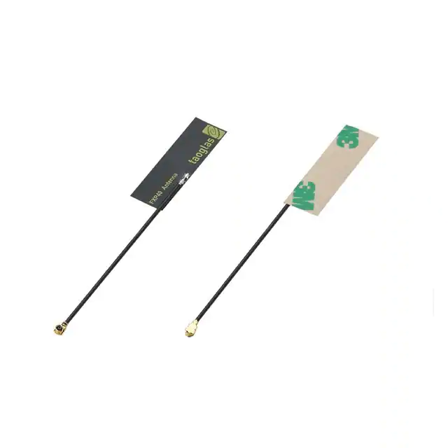
FXP40 Flexible PCB Antenna
Part No:
FXP40.07.0085A
Description:
4G LTE CAT-M NB-IoT Flexible PCB Antnna
Features:
700-960/1710-2200MHz Bands
1.9 dBi Peak Gain
Easy peel and stick adhesive
Dimension: 42.6*12.1*0.15mm
Connector: IPEX MHFI (U.FL Compatible)
Cable: 85mm 1.13mm cable
REACH & RoHS Compliant
SPE-14-8-053-D
�1.
Introduction
3
2.
Specifications
4
3.
Antenna Characteristics
5
4.
Radiation Patterns
7
5.
Mechanical Drawing
24
6.
Packaging
25
7.
Application Note
26
Changelog
28
Taoglas makes no warranties based on the accuracy or completeness of the contents of this document and reserves the right to
make changes to specifications and product descriptions at any time without notice. Taoglas reserves all rights to this document and
the information contained herein. Reproduction, use or disclosure to third parties without express permission is strictly prohibited.
SPE-14-8-053-D
www.taoglas.com
�1.
Introduction
1.
Introduction
1.
Introduction
1.
Introduction
1.
The Taoglas FXP40 is a super small monopole ultra low profile antenna for cellular and NB-IoT bands between
700 and 2200 MHz. The FXP40 has a peak gain of 1.3dBi and efficiencies of 56% are achievable if integrated
correctly.
1.
It is manufactured from a poly-flexible material, has a tiny form factor of just 42.6 x 12.1 x 0.15mm and is
supplied with a double-sided 3M tape for easy “peel and stick” mounting. It is designed to be mounted
directly onto a plastic and is an ideal choice for any device maker that needs to keep manufacturing costs at
a minimum over the lifetime of a product.
1.
1.
Introduction
Introduction
Introduction
Typical Applications include:
- Wearables
- Remote Monitoring
- Handheld devices
Introduction
The cables length can be customizable for customers. Contact your regional customer support team for
further information.
SPE-14-8-053-D
www.taoglas.com
�2.
Specifications
3.
Antenna Characteristics2.
Band
Frequency (MHz)
4G/3G
Efficiency Average Peak Gain
Impedance
Gain
(%)
(dBi)
(dB)
Freespace
12
-9.4
-2.7
698~806
3.Band 12,13,14,17,28,29
Antenna Characteristics
2mm ABS
17
4G/3G/NB-IoT/Cat M
Band
5,8,18,19,20,26,27
4.
824~960
Specifications
Electrical
-9.2
-3.1
Freespace
16
-8.1
-0.5
2mm ABS
25
-6.4
1.3
Max
Input
Power
50 Ω
2mm ABS
Characteristics2.
4G/3G
Band 7,30,38,40,41
2300~2690
-5.3
3.8
Specifications
Freespace
18
-7.9
0.7
2mm ABS
34
11
-10.8
Radiation Properties
Linear
Omni-Directional
5W
Freespace
56
-2.5
5.3
Antenna 1710~2200
Radiation
Patterns3.
Antenna
4G/3G
Band
1,2,3,4,9,23,25,35,39,66
Polarization
1.6
Mechanical
3.
3.
4.
Dimensions (mm)
Antenna
MaterialCharacteristics2.
46.2*12.1*0.15 mm
Specifications
Flexible Polymer
Connector and Cable
IPEX MHFI (U.FL Compatible) and 1.13 mm mini coax
Weight
1g
Operation Temperature
Antenna
Characteristics
Environmental
-40°C to 85°C
Storage Temperature
-40°C to 85°C
Relative Humidity
40% to 95%
RoHs Compliant
Yes
Antenna Radiation Patterns3.Antenna
*All results were measured with 85mm length 1.13mm coaxial cable and on 2mm thickness ABS base.
Characteristics
4.
Antenna Radiation Patterns
4.
Antenna Radiation Patterns3.Antenna
Characteristics
4.
Antenna Radiation Patterns3.Antenna
Characteristics2.
SPE-14-8-053-D
Specifications
www.taoglas.com
�3.
Antenna Characteristics
4.
Antenna Radiation Patterns3.Antenna
3.1
Return Loss
Characteristics
0
4.
Antenna Radiation Patterns
4.
Return Loss [dB]
-5
-10
-15
-20
Antenna
Radiation Patterns3.Antenna
-25
Characteristics
-30
Freespace
-35
4.
Antenna
Radiation Patterns3.Antenna
-40
600
Characteristics
3.2
4.
900
1200
1500
1800
2mm ABS
2100
2400
2700
3000
Frequency [MHz]
Efficiency
Antenna
Radiation Patterns
100
Freespace
90
2mm ABS
80
4.
Antenna
Radiation Patterns
70
Efficiency [%]
4.
60
50
40
Antenna
Radiation Patterns
30
20
4.
10
Antenna
Radiation Patterns3.Antenna
0
600
Characteristics
900
1200
1500
1800
2100
2400
2700
3000
Frequency [MHz]
4.
Antenna Radiation Patterns3.Antenna
SPE-14-8-053-D
www.taoglas.com
�3.3
Peak Gain
8
Freespace
6
2mm ABS
4
Gain [dBi]
2
0
-2
-4
-6
-8
-10
600
900
1200
1500
1800
2100
2400
2700
2100
2400
2700
3000
Frequency [MHz]
3.4
Average Gain
0
-2
-4
Aver Gain [dB]
-6
-8
-10
-12
-14
-16
Freespace
-18
2mm ABS
-20
600
900
1200
1500
1800
3000
Frequency [MHz]
SPE-14-8-053-D
www.taoglas.com
�4.
Radiation Patterns
4.
4.
Antenna Radiation Patterns
4.
Antenna Radiation Patterns
4.
Antenna Radiation Patterns
4.1
Test Setup
Z
4.
Antenna Radiation Patterns
4.
Antenna Radiation Patterns
4.
Antenna Radiation Patterns
4.
Antenna Radiation Patterns
SPE-14-8-053-D
www.taoglas.com
�4.2
750MHz Freespace - 3D and 2D Radiation Patterns
XY Plane
SPE-14-8-053-D
XZ Plane
YZ Plane
www.taoglas.com
�825MHz
XY Plane
SPE-14-8-053-D
XZ Plane
YZ Plane
www.taoglas.com
�880MHz
XY Plane
SPE-14-8-053-D
XZ Plane
YZ Plane
www.taoglas.com
�960MHz
XY Plane
SPE-14-8-053-D
XZ Plane
YZ Plane
www.taoglas.com
�1710MHz
XY Plane
SPE-14-8-053-D
XZ Plane
YZ Plane
www.taoglas.com
�1880MHz
XY Plane
SPE-14-8-053-D
XZ Plane
YZ Plane
www.taoglas.com
�1990MHz
XY Plane
SPE-14-8-053-D
XZ Plane
YZ Plane
www.taoglas.com
�2170MHz
XY Plane
SPE-14-8-053-D
XZ Plane
YZ Plane
www.taoglas.com
�4.3
750MHz On 2mm ABS - 3D and 2D Radiation Patterns
XY Plane
SPE-14-8-053-D
XZ Plane
YZ Plane
www.taoglas.com
�825MHz
XY Plane
SPE-14-8-053-D
XZ Plane
YZ Plane
www.taoglas.com
�880MHz
XY Plane
SPE-14-8-053-D
XZ Plane
YZ Plane
www.taoglas.com
�960MHz
XY Plane
SPE-14-8-053-D
XZ Plane
YZ Plane
www.taoglas.com
�1710MHz
XY Plane
SPE-14-8-053-D
XZ Plane
YZ Plane
www.taoglas.com
�1880MHz
XY Plane
SPE-14-8-053-D
XZ Plane
YZ Plane
www.taoglas.com
�1990MHz
XY Plane
SPE-14-8-053-D
XZ Plane
YZ Plane
www.taoglas.com
�2170MHz
XY Plane
SPE-14-8-053-D
XZ Plane
YZ Plane
www.taoglas.com
�5.
Mechanical Drawing (Units: mm)
6.
Packaging5.
6.
Packaging
7.
Application Note6. Packaging5.
Mechanical Drawing
Mechanical
Drawing
6.
Packaging5.
Mechanical Drawing
6.
Packaging
7.
Application Note6. Packaging
7.
Application Note
7.
Application Note6. Packaging
7.
Application Note6. Packaging5.
Mechanical
Drawing
6.
Packaging5.
SPE-14-8-053-D
Mechanical Drawing
www.taoglas.com
�8.
6.
Packaging
6.
Packaging5.
6.
Packaging
7.
Application Note6. Packaging5.
Mechanical Drawing
Mechanical
Drawing
6.
Packaging5.
Mechanical Drawing
6.
Packaging
7.
Application Note6. Packaging
7.
Application Note
7.
Application Note6. Packaging
7.
Application Note6. Packaging5.
Mechanical
Drawing
6.
Packaging5.
SPE-14-8-053-D
Mechanical Drawing
www.taoglas.com
�8.
7.
Packaging Note
Application
The FXP40 antenna measurement with difference cable length on plastic plate of 2 mm thickness, the
is shown as below.
6.performance
Packaging5.
Mechanical Drawing
3.1
Return Loss
6.
Packaging
7.
Application Note6. Packaging5.
Mechanical
Drawing
6.
Packaging5.
6.
Packaging
3.2
Mechanical Drawing
Efficiency
7.
Application Note6. Packaging
7.
Application Note
7.
Application Note6. Packaging
7.
Application Note6. Packaging5.
Mechanical
Drawing
6.
Packaging5.
SPE-14-8-053-D
Mechanical Drawing
www.taoglas.com
�3.3
Peak Gain
3.4
Average Gain
SPE-14-8-053-D
www.taoglas.com
�Changelog for the datasheet
SPE-14-8-053 - FXP40.07.0085A
Revision: D (Current Version)
Date:
Changes:
Changes Made by:
2022-04-21
Full datasheet update
Gary West
Previous Revisions
Revision: C
Date:
Changes:
Changes Made by:
2020-07-01
Updated Weight
Jack Conroy
Revision: B
Date:
Changes:
Changes Made by:
2019-04-11
Page 1 Features, page 3 Specification, page 4~5
Antenna Characteristicspage7~9 Antenna radiation
patterns, page11~12 Application Note.
David Connolly
Revision: A (Original First Release)
Date:
Notes:
Author:
SPE-14-8-053-D
2014-05-26
Technical Writer
www.taoglas.com
�© Taoglas
SPE-14-8-053-D
www.taoglas.com
�
很抱歉,暂时无法提供与“FXP40.07.0085A”相匹配的价格&库存,您可以联系我们找货
免费人工找货- 国内价格 香港价格
- 1+37.232491+4.82050