C
O
R
P
O
R
A
T
I
O
Analog Input
N
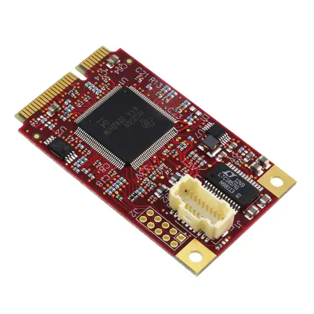
Mini PCIe Module
Extremely small Mini PCIe module format
Eight analog input channels
12 or 16-bit resolution
Industrial temp. (-40º to +85ºC) operation
MIL-STD-202G shock / vibe
Latching connector
Highlights
Overview
Mini PCIe Module Format
Analog Input
The VL-MPEe-A1 is an extremely small and rugged analog input module based on the industry-standard
Mini PCIe module format. Unlike typical I/O expansion boards, Mini PCIe allows additional I/O functions to
be added to a system with almost no increase in overall system / package size. Mini PCIe modules provide
a simple, economical, and standardized way to add I/O functions to embedded computer products.
Digital I/O
Details
Application Programming Interface
In a very small package, this analog board provides eight single-ended or four differential input channels.
The VL-MPEe-A1 model provides 12-bit resolution, while the VL-MPEe-A2 model provides 16-bit resolution.
Small and flexible.
Eight single-ended / four differential channels. 12 or 16-bit resolution.
Three GPIO lines.
Simplifies software development.
Industrial Temperature Operation
-40° to +85°C operation for harsh environments.
MIL-STD-202G
Qualified for high shock / vibration environments.
Latching Connector
Prevents detachment failures.
Class 3 Manufacturing (optional)
IPC-A-610 Class 3 for applications requiring extreme reliability.
Operating at 100,000 samples per second, each input channel is individually configurable for an input range
of 0 to 5V, -5 to +5V, 0 to +10V, and -10 to +10V.
In addition, the board provides three general purpose digital I/O lines which are independently configurable
for input, output, or interrupts.
This rugged product is designed and tested for full industrial temperature operation (-40º to +85ºC). It also
meets MIL-STD-202G specifications for shock and vibration, making it at home in harsh environments.
The VL-MPEe-A1 board is supported by device drivers and the VersaAPI Application Programing Interface.
The VersaAPI includes pre-defined calls to send or retrieve data from the on-board I/O ports. These calls
greatly simplify development of the user code needed to access these ports. On the VL-MPEe-A1 board, the
VersaAPI supports the on-board A/D channels and GPIO lines. The VersaAPI is compatible with Windows,
Windows Embedded, and Linux operating systems.
This analog input board is compatible with a variety of popular x86 operating systems including Windows,
Windows Embedded, and Linux.
The module utilizes PCIe signaling and can be used in any system that supports PCIe signaling at the
Mini PCIe socket.
It is manufactured to IPC-A-610 Class 2 standards. Class 3 versions are available for extremely-highreliability applications.
Product customization is available, even in low quantities. Options include FPGA customization, conformal
coating, application-specific testing, BOM revision locks, special labeling, etc.
VersaLogic Corporation • Tualatin, OR • (503) 747-2261 • Info@VersaLogic.com • www.VersaLogic.com
�C
O
R
P
O
R
A
T
I
O
Analog Input
Mini PCIe Module
N
Specifications
Ordering Information
Model
Function
VL-MPEe-A1E
VL-MPEe-A2E
Analog input. Eight channel. 12-bit resolution.
Analog input. Eight channel. 16-bit resolution.
Operating
Temp.
-40° to +85°C
-40° to +85°C
Environmental
Accessories
Part Number
Cables
VL-CBR-2004
Hardware
VL-HDW-108
VL-HDW-110
General
Description
Board Size
Power Requirements
Manufacturing Standards
Regulatory Compliance
Mini PCIe Signal Type
Operating Temperature
Storage Temperature
Altitude *
Cooling
Airflow Requirements
Thermal Shock
Humidity
Vibration, Sinusoidal
Sweep †
Vibration, Random †
Breakout cable and paddleboard, 20-pin
Mini PCIe module hold-down screws (10) for use with 2.5 mm standoffs
Mini PCIe module hold-down screws (10) for use with 2.0 mm standoffs
Mechanical Shock †
Device I/O
Analog Input
GPIO
Software
Drivers
Mini PCIe module (full size): 30 mm x 50.95 mm x 6.37 mm
3.3V ±5% @ 0.45W (from the Mini PCIe socket)
Standard
IPC-A-610 Class 2 modified
Optional
IPC-A-610 Class 3 modified
RoHS
PCI Express Base Specification, Rev 2.0
-40° to +85°C
-40° to +85°C
Operating
To 15,000 ft. (4,570m)
Storage
To 40,000 ft. (12,000m)
None (fanless)
None (free air)
5°C/min. over operating temperature
Less than 95%, noncondensing
MIL-STD-202G, Method 204, Modified Condition A: 2g
constant acceleration from 5 to 500 Hz, 20 min. per axis
MIL-STD-202G, Method 214A, Condition A: 5.35g rms,
5 min. per axis
MIL-STD-202G, Method 213B, Condition G: 20g half-sine,
11 msec. duration per axis
Eight single-ended or four differential pairs. 12 or 16-bit
resolution (depends on model). 100 Ksps. Softwareconfigurable per-channel input ranges of 0 to +5V, ±5V, 0
to +10V, and ±10V.
Three general purpose 3.3V digital I/O lines. Each line
independently configurable as input, output, or interrupt.
Device drivers and VersaAPI included. Provides simplified
I/O interface for most application languages. Supports
on-board A/D channels and GPIO lines. Compatible with
Windows, Windows Embedded, and Linux operating
systems.
* Extended altitude specifications available upon request
†† MIL-STD-202G shock and vibe levels are used to illustrate the ruggedness of this product in general. Testing to higher
levels and / or different types of shock or vibration methods can be accommodated per the specific requirements of the
application. Contact a VersaLogic Sales Engineer for further information.
Specifications are subject to change without notification. PCI Express is a registered trademark of the PCI-SIG. All other
trademarks are the property of their respective owners.
03/16/16
VersaLogic Corporation • Tualatin, OR • (503) 747-2261 • Info@VersaLogic.com • www.VersaLogic.com
�
