IQ Switch®
ProxSense® Series
IQS333EV02 Evaluation Kit User Guide
IQ Switch® - ProxSense® Series
Table of Contents
1
Introduction.............................................................................................................................. 1
2
Connection Board and IQS333 IC ........................................................................................... 1
3
Wheel Board............................................................................................................................ 3
4
Cross Board ............................................................................................................................ 5
5
Reference Designs .................................................................................................................. 6
1 Introduction
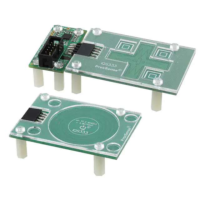
This user guide describes the operation of the IQS333EV02 Evaluation Kit. The EV-Kit consists of
3 parts, the connection board, the wheel board and the cross board. The quick start guide is also
included. To visualise raw data from the EV-Kit, the connection board can be interfaced to any
personal computer with USB support, and IQS333 software Graphical User Interface (GUI). The
purpose of the IQS333EV02 EV-Kit is to help application and development engineers in evaluating
the IQS333’s 9 channel projected- and 7 channel self-capacitive proximity and touch sensors. A
picture of the evaluation kit is shown below.
Figure 1.1 Connection board (left), wheel module board (middle) and cross module
board (right)
This user guide will help a user to fully use and understand the technology in this evaluation kit.
The connection board will be described, followed by the wheel module board and the cross
module board. This will be shown in conjunction with an IQS333 GUI (Graphical User Interface) to
simplify explanations.
2 Connection Board and IQS333 IC
The IQS333 IC (Integrated Circuit) is located on the connection board. The IQS333 can be used in
self-capacitive mode with up to 7 channels or in projected capacitive mode with up to 9 channels.
In self-capacitive mode it can be used as 7 buttons or 1 slider with 4 buttons or 2 sliders with 1
button. In projected capacitive mode it can be used as 9 buttons or 1 slider with 6 buttons or 2
sliders with 3 buttons.
The IQS333 has a configurable PWM controller which is used to drive LEDs and can be used as a
general output pin. Figure 2.1 and Figure 2.2 shows the working of the PWM controller. Figure 2.1
shows the switched on LEDs on the connection board. This is achieved by running the IQS333
GUI through following the next steps.
Run IQS333 Application
Read and Close the Hints & Tips menu
Click the Start button
Click the Wheels/Slider bar to get to the Compensation/Multiplier/Thresholds bar.
Copyright © Azoteq (Pty) Ltd 2014
All Rights Reserved
IQS333EV02 Evaluation Kit User Guide
Revision 1.0
Page 1 of 8
February 2014
�IQ Switch®
ProxSense® Series
Set the Mode to “Const” (Constant) and “CMP” (Compare) value to 31.
Click the Send button.
The LEDs on the connection board should turn on as shown below.
Figure 2.1 Connection board with PWM LEDs switched on
The GUI should look similar to the screenshot below with the relevant settings highlighted.
Figure 2.2 Switch PWM LEDs on with IQS333 GUI
The connection board has 2 10-way headers, 1 box header for communicating with a
microcontroller, such as a CT210, and a straight DIL header for connecting to the sense
electrodes. The pin outs for the headers are numbered in Figure 2.3 and each pins description is
given in Table 1. This is given as users may wish to connect their own sensing electrodes to the
IQS333.
Copyright © Azoteq (Pty) Ltd 2014
All Rights Reserved
IQS333EV02 Evaluation Kit User Guide
Revision 1.0
Page 2 of 8
February 2014
�IQ Switch®
ProxSense® Series
Box header
2
4
1
6
3
8
10
Straight DIL header
9
5
7
1
2
3
4
5
6
7
8
9
10
Figure 2.3 Connection board pin outs
Table 1 Connection board pin out description
Header 1 Box header
Pin number – Description
1 – Ground
2 – No connect
3 – VDDHI
4 – No connect
5 – No connect
6 – No connect
7 – I2C Data
8 – No connect
9 – I2C Clock
10 – Ready
Header 2 Straight DIL header
Pin number – Description
1 – CTRX0/RX0
2 – CTRX4/TX1
3 – CTRX1/RX1
4 – CTRX5/TX2
5 – CTRX2/RX2
6 – CTRX6
7 – CTRX3/TX0
8 – No connect
9 – No connect
10 – Ground
3 Wheel Board
The IQS333EV02 Kit comes with 2 module boards: the wheel and the cross module boards. First
we look at the working of the wheel board. Always remember to click the Stop button before
removing or connecting a module board. When the wanted board is connected click the Start
button to continue evaluating. This Stop and Start is needed for the software to ensure that no
errors occur.
To evaluate the wheel module board, connect the wheel module board to the connection board as
shown in the figure below.
Copyright © Azoteq (Pty) Ltd 2014
All Rights Reserved
IQS333EV02 Evaluation Kit User Guide
Revision 1.0
Page 3 of 8
February 2014
�IQ Switch®
ProxSense® Series
Figure 3.1 Wheel board plugged into connection board
Figure 3.2 IQS333 GUI setup for wheel board
This is achieved through the following steps:
Click the Stop button.
Connect the wheel board to the connection board.
Click the Start button.
Click the Wheel Demo icon under the Demos tab.
The GUI is now setup as shown in Figure 3.2 above. Evaluate the board by sliding a finger on the
big wheel in the centre of the board in a circular motion. This will correspond to Wheel 1 on the left
side of the GUI and Channels 1 to 3. Channel 0 is a distributed proximity channel and activates
when a finger comes close to a Channel. Channels 4 to 7 represent the four touch buttons at each
corner of the Wheel board. After we are done evaluating the Wheel module board, we move on to
the Cross module board.
Copyright © Azoteq (Pty) Ltd 2014
All Rights Reserved
IQS333EV02 Evaluation Kit User Guide
Revision 1.0
Page 4 of 8
February 2014
�IQ Switch®
ProxSense® Series
4 Cross Board
The next board to evaluate is the Cross module board. Remember to click the Stop button, replace
the Wheel board with the Cross board and then click the Start button to avoid unwanted errors.
The connection board with the cross board plugged in is shown below.
Figure 4.1 Cross board plugged into connection board
Figure 4.2 IQS333 GUI setup for cross board
Get the Cross board setup by following the next couple of steps:
Click the Stop button.
Remove the Wheel board from the connection board.
Connect the Cross board to the connection board.
Click the Start button.
Click the Cross Demo icon under the Demos tab.
The GUI resembles that of Figure 4.2 above. Evaluate the Cross board by sliding a finger over the
vertical and horizontal parts of the cross. The vertical slider (vertical bar of the cross) relates to
Wheel 1 on the left of the GUI and correlates to Channel 1 to 3. Note that in the middle of the
cross, Channels 2 and 5 will be activated as this is where the two sliders cross. The horizontal
slider (horizontal bar of the cross) relates to Wheel 2 on the right of the GUI and correlates to
Channel 4 to 6, additionally it also relates to the slider at the bottom of the GUI. The 3 square
Copyright © Azoteq (Pty) Ltd 2014
All Rights Reserved
IQS333EV02 Evaluation Kit User Guide
Revision 1.0
Page 5 of 8
February 2014
�IQ Switch®
ProxSense® Series
buttons relate to Channels 7 to 9 in the GUI. Evaluate this module board fully to see all the
capabilities that this board provide.
On the right and bottom of the GUI there are multiple settings that can be changed. For a first time
user we suggest to leave these settings and first evaluate the boards with the loaded settings.
After evaluation the user can make adjustments to these settings for application specific options.
This will help the user in achieving more/less sensitive buttons and various other settings.
5 Reference Designs
For further technical detail the datasheet should be consulted and can be found at the Azoteq
website. Some reference designs from the datasheet are shown below.
Figure 5.1 IQS333 Self Capacitive Reference Design
Copyright © Azoteq (Pty) Ltd 2014
All Rights Reserved
IQS333EV02 Evaluation Kit User Guide
Revision 1.0
Page 6 of 8
February 2014
�IQ Switch®
ProxSense® Series
Figure 5.2 IQS333 Projected Capacitive Reference Design
Copyright © Azoteq (Pty) Ltd 2014
All Rights Reserved
IQS333EV02 Evaluation Kit User Guide
Revision 1.0
Page 7 of 8
February 2014
�IQ Switch®
ProxSense® Series
Appendix A
Contact Information
USA
6507 Jester Blvd
Bldg 5, suite 510G
Austin
TX 78750
USA
Asia
Rm1725, Glittery City
Shennan Rd
Futian District
Shenzhen, 518033
China
South Africa
109 Main Street
Paarl
7646
South Africa
Postal
Address
6507 Jester Blvd
Bldg 5, suite 510G
Austin
TX 78750
USA
Rm1725, Glittery City
Shennan Rd
Futian District
Shenzhen, 518033
China
PO Box 3534
Paarl
7620
South Africa
Tel
+1 512 538 1995
+86 755 8303 5294
ext 808
+27 21 863 0033
Fax
+1 512 672 8442
Email
kobusm@azoteq.com
Physical
Address
+27 21 863 1512
linayu@azoteq.com.cn
info@azoteq.com
Please visit www.azoteq.com for a list of distributors and worldwide representation.
The following patents relate to the device or usage of the device: US 6,249,089 B1, US 6,621,225 B2, US 6,650,066
B2, US 6,952,084 B2, US 6,984,900 B1, US 7,084,526 B2, US 7,084,531 B2, US 7,265,494 B2, US 7,291,940 B2,
US 7,329,970 B2, US 7,336,037 B2, US 7,443,101 B2, US 7,466,040 B2, US 7,498,749 B2, US 7,528,508 B2, US
7,755,219 B2, US 7,772,781, US 7,781,980 B2, US 7,915,765 B2, US 7,994,726 B2, US 8, 035,623 B2, US
8,288,952 B2, EP 1 120 018 B1, EP 1 206 168 B1, EP 1 308 913 B1, EP 1 530 178 B1, ZL 200880005683.2, ZL 99
8 14357.X, AUS 761094, HK 104 14100A
®
®
®
IQ Switch , SwipeSwitch™, ProxSense , LightSense™, AirButton and the
logo are trademarks of Azoteq.
The information in this Datasheet is believed to be accurate at the time of publication. Azoteq uses reasonable effort to maintain the information up-to-date and accurate, but does not warrant
the accuracy, completeness or reliability of the information contained herein. All content and information are provided on a “as is” basis only, without any representations or warranties, express
or implied, of any kind, including representations about the suitability of these products or information for any purpose. Azoteq disclaims all warranties and conditions with regard to these
products and information, including but not limited to all implied warranties and conditions of merchantability, fitness for a particular purpose, title and non-infringement of any third party
intellectual property rights. Azoteq assumes no liability for any damages or injury arising from any use of the information or the product or caused by, without limitation, failure of performance,
error, omission, interruption, defect, delay in operation or transmission, even if Azoteq has been advised of the possibility of such damages. The applications mentioned herein are used solely
for the purpose of illustration and Azoteq makes no warranty or representation that such applications will be suitable without further modification, nor recommends the use of its products for
application that may present a risk to human life due to malfunction or otherwise. Azoteq products are not authorized for use as critical components in life support devices or systems. No
licenses to patents are granted, implicitly, express or implied, by estoppel or otherwise, under any intellectual property rights. In the event that any of the abovementioned limitations or
exclusions does not apply, it is agreed that Azoteq’s total liability for all losses, damages and causes of action (in contract, tort (including without limitation, negligence) or otherwise) will not
exceed the amount already paid by the customer for the products. Azoteq reserves the right to alter its products, to make corrections, deletions, modifications, enhancements, improvements
and other changes to the content and information, its products, programs and services at any time or to move or discontinue any contents, products, programs or services without prior
notification. For the most up-to-date information and binding Terms and Conditions please refer to www.azoteq.com.
WWW.AZOTEQ.COM
info@azoteq.com
Copyright © Azoteq (Pty) Ltd 2014
All Rights Reserved
IQS333EV02 Evaluation Kit User Guide
Revision 1.0
Page 8 of 8
February 2014
�