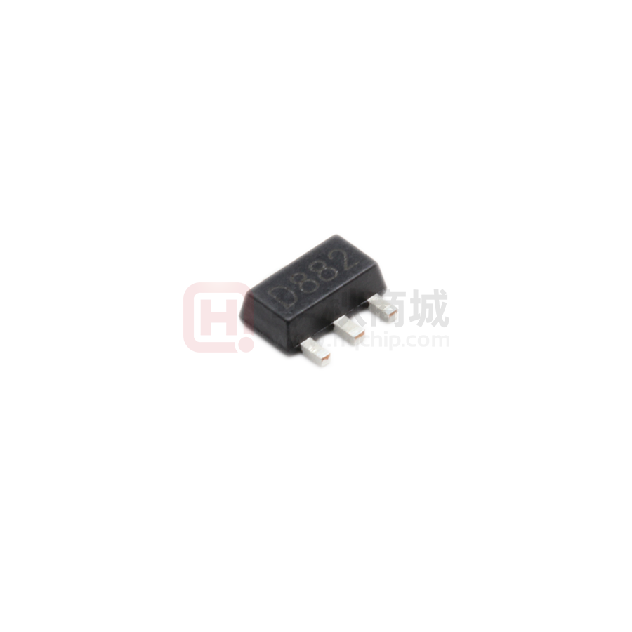
D882
NPN Silicon Power Transistor
The transistor is subdivided into four groups, R, Q,
P and E, according to its DC current gain.
Absolute Maximum Ratings (Ta = 25 OC)
Symbol
Value
Unit
Collector to Base Voltage
VCBO
40
V
Collector to Emitter Voltage
VCEO
30
V
Emitter to Base Voltage
VEBO
5
V
Collector Current
IC
3
A
Peak Collector Current (t = 10 ms)
ICP
7
A
Total power dissipation (Ta = 25 OC)
Ptot
1
W
Total power dissipation (Tc = 25 C)
Ptot
10
W
Tj
150
O
Tstg
- 55 to + 150
O
Symbol
Min.
Typ.
Max.
Unit
hFE
hFE
hFE
hFE
hFE
30
60
100
160
200
-
120
200
320
400
-
Collector Base Cutoff Current
at VCB = 30 V
ICBO
-
-
1
µA
Emitter Base Cutoff Current
at VEB = 3 V
IEBO
-
-
1
µA
Collector Emitter Saturation Voltage
at IC = 2 A, IB = 0.2 A
VCE(sat)
-
-
0.5
V
Base Emitter Saturation Voltage
at IC = 2 A, IB = 0.2 A
VBE(sat)
-
-
2
V
Gain Bandwidth Product
at VCE = 5 V, IC = 0.1 A
fT
-
90
-
MHz
Output Capacitance
at VCB = 10 V, f = 1 MHz
Cob
-
45
-
pF
Parameter
O
Junction Temperature
Storage Temperature Range
C
C
Characteristics at Ta = 25 OC
Parameter
DC Current Gain
at VCE = 2 V, IC = 20 mA
at VCE = 2 V, IC = 1 A Current Gain Group
R
O
Y
GR
2012-7-8
- 1-
�D882
o
TYPICAL CHARACTERISTICS (Ta=25 C)
TOTAL POWER DISSIPATION vs.
AMBIENT TEMPERATURE
NOTE
1.Aluminum heat sink
of 1.0 mm thickness.
2.With no insulator film.
3.With silicon compound.
he
at
4
25c
m
2
9cm 2
2
Without
heat sin
k
0
0
50
100
60
40
20
10
3
1
0.3
0.1
0
150
ite
d
d
ite
m
Li
nk
si
100
cm 2
Lim
Rth-Thermal Resistance- oC/W
ite
fin
6
S/b
80
n
io
at
ip
ss
Di
dT-Percentage of Rated Current-%
8
VCE=10V
I C=1.0A
30 Duty=0.001
100
In
P T-Total Power Dissipation-W
10
THERMAL RESISTANCE vs.
PULSE WIDTH
DERATING CURVES FOR ALL TYPES
50
100
0.3
150
1
10
3
30
100 300
1000
PW-Pulse Width-mS
o
Ta-Ambient Temperature - C
Tc-Case Temperature -o C
0.3
I C-Collector Current-A
1
0.1
0.03
NOTE
1.T C=25o C
2.Curves must be derated
Iinearly with increase of
temperature and Duty Cycle.
3
6
10
7
1.2
6
5
0.8
4
3
0.4
30
60
4
12
8
0.3
3
1
3
10
0.1
20
3
10
100
30
10
3
Cib
100
60
30
Cob
10
6
3
1
0.01
I C-Collector Current-A
f=1.0MHz
I E =0(Cob)
I C=0(Cib )
300
Cib -Input Capacitance-pF
Cob-Output Capacitance-pF
VCE(sat)
0.01
0.006
0.003
INPUT AND OUTPUT CAPACITANCE vs.
REVERSE VOLTAGE
VCE=5.0V
Forced air
cooling
(with heat sink)
300
1
16
GAIN BANDWIDTH PRODUCT vs.
COLLCETOR CURRENT
1000
VBE(sat)
0.001 0.003 0.01 0.03 0.1 0.3
1
0.6
VBE
I C-Collector Current-A
I C=10.I B
Pulse Test
0.1
0.06
0.03
10
6
3
o Voltage-V
VCE-Collector to Emitter
f T-Gain Bandwidth Product-MHz
VBE(sat) -Base Saturation Voltage-v
VCE(sat)-Collector Saturation Voltage-V
1
0.6
0.3
30
100
BASE AND COLLECTOR SATURATION
VOLTAGE vs. COLLECTOR CURRENT
3
60
1
0.001 0.003 0.01 0.03 0.1 0.3
0
VCE-Collector to Emitter Voltage-V
10
2
h FE
100
I B =1mA
0.01
1
300
10
9
8
1.6
VCEO MAX.
IC-Collector Current-A
3
VCE=2.0V
Pulse Test
Pulse Test
h FE -DC Current Gain
I C(pulse) MAX.(PW 10ms,Duty Cycle 50%)
PW
1m
10
s
=1
I C(DC) MAX.
ms
00
DC
s
Di
s
(S
sip
ing
at
Li
i
le
o
S
m
n
no
/b
ite
nr
Li
d
ep
m
et
it e
iti
d
ve
pu
lse
)
VBE -Base Emitter Voltage-V
1000
2.0
10
DC CURRENT GAIN, BASE TO EMITTER
VOLTAGE vs. COLLECTOR CURRENT
COLLECTOR CURRENT vs.
COLLECTOR TO EMITTER VOLTAGE
SAFE OPERATING AREAS
0.03
0.1
I C-Collcetor Current-A
0.3
1
1
3
6
10
30
60
VCB-Collector to Base Voltage-V
VEB -Emitter to Base Voltage-V
-2 -
�D882
SOT-89 PACKAGE OUTLINE
2012-7-8
- 3-
�
很抱歉,暂时无法提供与“D882”相匹配的价格&库存,您可以联系我们找货
免费人工找货- 国内价格
- 20+0.77610
- 100+0.46300
- 500+0.32410
- 1000+0.23150
- 2000+0.21990
- 10000+0.20370
- 国内价格
- 5+0.43697
- 50+0.34884
- 150+0.30473
- 1000+0.24173
- 2000+0.21536
- 5000+0.20213
- 国内价格
- 1+0.23807
- 10+0.22912
- 100+0.20764
- 500+0.19690
