AS1357
D a ta S he e t
P r o g r a m m a b l e Tr i p l e L D O
1 General Description
2 Key Features
!
3 Independent Voltage Regulators with Shutdown
!
Output Current: 200mA each LDO
!
One Time Programmable Output Voltage
(User- or Factory-Trimmed)
!
Programmable Output Voltage Range: 1.8 to 3.3V in
0.1V Steps
!
Accuracy: ±1.5%
!
PSRR: 70dB at 1kHz, 40dB at 100kHz
!
Line Regulation: ±2mV
!
Load Regulation: ±0.6mV
!
Supply Range: 3 to 5.5V
!
0.2V Dropout Voltage @ I = 200mA
!
Shutdown Current: ≤1µA
!
Supply Current Without Load: 175µA (typ)
!
Softstart for Low Inrush Current
Regulation performance is excellent even under low
dropout conditions, when the power transistor has to
operate in linear mode.
!
Stable with low ESR Ceramic Capacitors from 1 to
4.7µF
!
Low Noise: 40µV rms @10Hz to 100kHz Bandwidth
The low-noise performance allows direct connection of
noise sensitive circuits without additional filtering networks.
!
Thermal Protection
!
Over-Current Protection
!
Temperature Range: -40 to +85°C
!
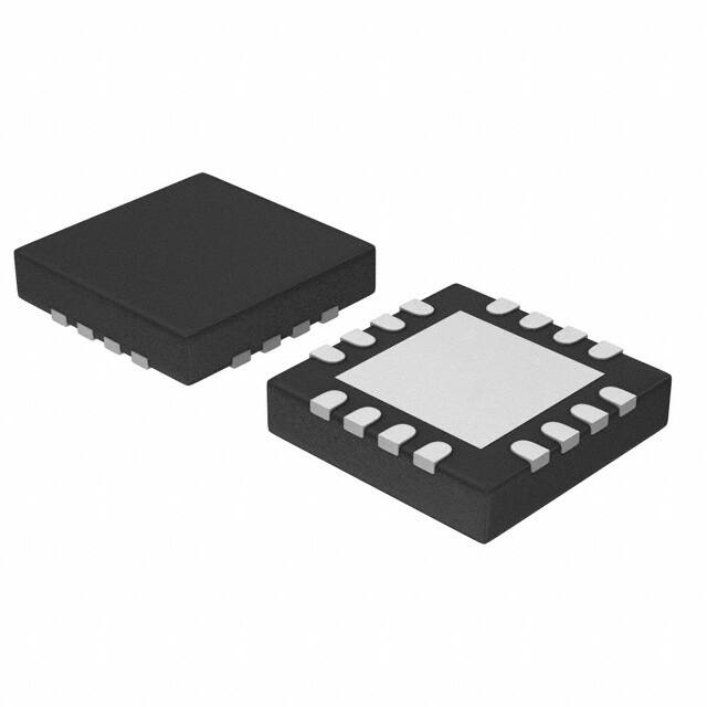
Package Types: 12-pin QFN 4x4 and
16-pin QFN 3x3
The AS1357 is a high-performance triple CMOS lowdropout voltage regulator in a single QFN package. The
efficient set of programmable power supplies is optimized to deliver the best compromise between quiescent current and regulator performance for mobile
phones, PDAs, MP3 players, and other battery powered
devices.
The one-time-programmable (OTP) function provides
greater design flexibility by allowing for independent programming of the output voltage for each regulator onsite. The OTP function allows for fast prototyping reducing development times and costs significant. Factory
trimmed versions for full-production are also available.
Stability is guaranteed with ceramic output capacitors of
only 1µF (±20% – X5R) up to 4.7µF (±20% – X5R). The
low equivalent series resistance (ESR) of these capacitors ensures low output impedance at high frequencies.
The AS1357 is available in a 12-pin QFN 4x4 or 16-pin
QFN 3x3 package.
3 Applications
The AS1357 is ideal for cordless and mobile phones,
MP3 players, CD and DVD players, PDAs, handheld
computers, digital cameras, and any other hand-held
battery-powered device.
Figure 1. Pinout Assignments (Top View)
EN2
EN3
N/C
REF
EN2
EN3
N/C
REF
12
11
10
16
15
14
13
9
1
AS1357
EN1
VDD
12-pin QFN
4x4
2
8
3
7
4
5
6
VOUT1 VOUT2 VOUT3
www.austriamicrosystems.com
EN1
1
VDD
2
VDD
3
VDD
4
12 GND
GND
11 GND
AS1357
16-pin QFN
3x3
VDD
10 VDD
N/C
13
GND
(Exposed Pad)
Revision 1.07
9
5
6
7
VOUT1 VOUT2 VOUT3
VDD
8
N/C
1 - 10
�AS1357
Data Sheet
- Pinout
4 Pinout
Pin Assignments
Figure 2. Pin Assignments (Top View – Not To Scale)
EN2
EN3
N/C
REF
EN2
EN3
N/C
REF
12
11
10
16
15
14
13
1
9
EN1
VDD
2
8
7
3
4
5
6
VOUT1 VOUT2 VOUT3
1
VDD
2
12 GND
GND
AS1357
12-pin QFN
4x4
EN1
VDD
VDD
3
VDD
4
11 GND
AS1357
16-pin QFN
3x3
10 VDD
N/C
13
GND
9
6
5
(Exposed Pad)
7
VOUT1 VOUT2 VOUT3
VDD
8
N/C
Pin Descriptions
Table 1. Pin Descriptions
12-pin QFN 4x4 16-pin QFN 3x3
Pin Number
Pin Number
Pin Name
Description
2
1
EN1
VOUT1 Digital Input Enable
1
16
EN2
VOUT2 Digital Input Enable
12
15
EN3
VOUT3 Digital Input Enable
9
11, 12
GND
Negative Supply Voltage.
Note: All GND pins must be connected together externally.
13
-
GND
Negative Supply Voltage. This pin is the exposed pad.
Note: All GND pins must be connected together externally.
10
13
REF
Analog Reference Voltage.
Note: Connect to 100nF capacitor during normal operation.
3, 8
2, 3, 4, 9, 10
VDD
Positive Supply Voltage.
Note: All VDD pins must be connected together externally.
4
5
VOUT1
Regulated Analog Output Voltage 1
5
6
VOUT2
Regulated Analog Output Voltage 2
6
7
VOUT3
Regulated Analog Output Voltage 3
7,11
8, 14
N/C
www.austriamicrosystems.com
Not connected.
Revision 1.07
2 - 10
�AS1357
Data Sheet
- Absolute Maximum Ratings
5 Absolute Maximum Ratings
Stresses beyond those listed in Table 3 may cause permanent damage to the device. These are stress ratings only,
and functional operation of the device at these or any other conditions beyond those indicated in the operational sections of the specifications is not implied. Exposure to absolute maximum rating conditions for extended periods may
affect device reliability.
Table 2. Absolute Maximum Ratings
Parameter
Min
Max
Units
VDD to GND
-0.3
7
V
Any other pin to GND
-0.3
VDD + 0.3
V
Continuous Power Dissipation
QFN12 4x4mm
1100
2800
mW
Min value measured at TAMB = 85°C;
max value measured at TAMB = 25°C.
260
°C
The reflow peak soldering temperature (body
temperature) specified is in accordance with
IPC/JEDEC J-STD-020C “Moisture/Reflow
Sensitivity Classification for non-hermetic
Solid State Surface Mount Devices”.
Package-Body Peak
Temperature
Operating Temperature
-40
85
°C
Storage Temperature
-65
150
°C
Electrostatic Discharge
Protection (ESD) Level
1
www.austriamicrosystems.com
kV
Revision 1.07
Comments
HBM – Norm: MIL 883 E method 3015.
3 - 10
�AS1357
Data Sheet
- Electrical Characteristics
6 Electrical Characteristics
VDD = 4V; TAMB = -40 to +85°C (Typ values are for TAMB = 25°C); CLOAD = 1µF (Ceramic); unless otherwise specified.
Table 3. Electrical Characteristics
Symbol
Parameter
VDD
Supply Voltage Range
VOUT
Output Voltage Range
RON
On Resistance
PSRR 1
Power Supply
Rejection Ratio
f = 1kHz, CREF = 100nF
70
f = 100kHz, CREF = 100nF
40
IOFF
Shut Down Current
ENx = Low
IVDD
Supply Current
Without Load
tset 1
Output Voltage
Settling Time
tstart 1
Start-up Time 2
VOUT
Output Voltage Tolerance
VLINEREG
Line Regulation, Static
VLOADREG
Load Regulation, Static
VIH
Enable Input Voltage High
VIL
Enable Input Voltage Low
ILOAD
Output Current
ILIMIT
Output Current Limitation
VNoise
Output Noise Voltage
Conditions
Min
Typ
Max
Unit
3
5.5
V
1.8
3.3
V
1
Ω
dB
1
µA
275
µA
ILOAD Switched from 0 to 100mA
50
µs
CREF = 100nF Pre-charged
300
µs
175
CREF = 0nF Uncharged
300
µs
CREF = 100nF Uncharged
15
ms
ILOAD = 0mA, TAMB = 25°C
-1.5
1.5
%
ILOAD = 0 to 200mA
-2
2
%
VDD = 5.5V
-1
1
%
VDD = 3 to 4.5V
-2
2
mV 1
ILOAD = 0 to 50 mA
0.3
2.5
mV 1
ILOAD = 0 to 200 mA
(referenced to 100mA)
0.6
5
mV 1
0.6 x VDD
V
0
10 to 100kHz, CREF = 100nF
Thermal Protection
0.8
V
200
mA
400
mA
40
µVRMS
145
°C
Notes:
1. Guaranteed by design and verified by lab evaluation.
2. Startup is performed if any EN pin goes high.
www.austriamicrosystems.com
Revision 1.07
4 - 10
�AS1357
Data Sheet
- Ty p i c a l A p p l i c a t i o n
7 Typical Application
Figure 3. Typical AS1357_uxy Application
VDD
VOUT1
3V
2.8V
VPERI
1µF ±20% (X5R)
2.2µF +100/-50%
(Z5U)
VOUT2
CMOS
Sensor
2.5V
VCORE
1µF ±20% (X5R)
2.2µF +100/-50%
(Z5U)
VOUT3
2.8V
VPERI
1µF ±20% (X5R)
2.2µF +100/-50%
(Z5U)
EN1
Microprocessor
EN2
Microprocessor
EN3
AS1357_A7A
REF
100nF (Improved Noise Performance)
GND
GND
One-Time Programming Procedure Output Voltages
The three LDOs can be programmed and burned to any output voltage between 1.8 and 3.3V in steps of 0.1V. Customers can burn the desired output voltages onsite using the austriamicrosystems programming board.
Furthermore, the AS1357 is available in pre-programmed versions with fixed output voltages (see Ordering Information
on page 9.)
www.austriamicrosystems.com
Revision 1.07
5 - 10
�AS1357
Data Sheet
- Ty p i c a l A p p l i c a t i o n
Figure 4. AS1357 Block Diagram
VDD
VOUT1
Thermal
Protection
Overcurrent
Protection
Softstart
VREF
EN1
Control
VOUT2
Thermal
Protection
Overcurrent
Protection
Softstart
VREF
EN2
Control
VDD
VOUT3
Thermal
Protection
Overcurrent
Protection
Softstart
VREF
EN3
Control
Reference
Voltage
GND
www.austriamicrosystems.com
REF
AS1357
Revision 1.07
6 - 10
�AS1357
Data Sheet
- Package Drawings and Markings
8 Package Drawings and Markings
The AS1357 is available in a 12-pin QFN 4x4 package and a 16-pin QFN 3x3 package.
Figure 5. 12-pin QFN 4x4 and 16-pin QFN 3x3 Packages
D2
-A-
D
D2/2
D/2
Index Area
(D/2 xE/2)
-B-
-B-
aaa C 2x
E
See
Detail B
E2
E2/2
e
E/2
NXL
4
2
1
Pin 1
Marker
aaa C 2x
4
SEE
Detail B
NXb
-A-
N N-1
6
Index Area
(D/2 xE/2)
5
bbb
ddd
C A B
C
Bottom View
Top View
11
0.08 C
NX
Seating
Plane
Side View
Datum A or B
Datum A or B
12
12
e
Even Terminal Side
L1
L1
e/2
-C-
A3
9
A1
8
A
ccc C
Terminal Tip
e
Terminal Tip
5
5
Detail B
Odd Terminal Side
Notes:
1. Dimensioning and tolerancing conform to ASME Y14.5M-1994.
2. All dimensions are in millimeters; angles in degrees.
www.austriamicrosystems.com
Revision 1.07
7 - 10
�AS1357
Data Sheet
3. N is the total number of terminals.
4. The terminal #1 identifier and terminal numbering convention shall conform to JEDEC 95 SPP-012. Details of terminal #1 identifier are optional but must be located within the zone indicated. The terminal #1 identifier may be either
a mold or marked feature.
5. Dimension b applies to metallized terminal and is measured between 0.15 and 0.30mm from terminal tip. If one end
of the terminal has the optional radius, the b dimension should not be measured in that radius area.
6. Dimensions ND and NE refer to the number of terminals on each D and E side, respectively.
7. Depopulation is possible in a symmetrical fashion.
8. Figure 5 is shown for illustration only and does not represent any specific variation.
9. All variations may be constructed per Figure 5, however variations may alternately be constructed between square
or rectangle shape per dimensions D and E.
10. Refer to the Dimensions Table for a complete set of dimensions.
11. Bilateral coplanarity zone applies to the exposed heat sink slug as well as the terminals.
12. Depending on the method of lead termination at the edge of the package, pullback (L1) may be present. L minus
L1 to be ≥ 0.33mm.
13. For variations with more than one lead count for a given body size and terminal pitch, each lead count for that variation is denoted by a dash number (e.g., -1 or -2).
16-pin QFN 3x3 Dimensions
Symbol
Min
aaa
Nom
Max
0.15
12-pin QFN 4x4 Dimensions
Notes
Symbol
1, 2
aaa
Min
Nom
0.15
Max
Notes
1, 2
bbb
0.10
1, 2
bbb
0.10
1, 2
ccc
0.10
1, 2
ccc
0.10
1, 2
ddd
b
0.05
0.18
e
0.25
1, 2
ddd
0.30
1, 2
b
0.50
0.05
0.25
e
0.30
1, 2
0.35
1, 2
0.80
A
0.80
0.90
1.00
1, 2
A
0.80
0.90
1.00
1, 2
A1
0.00
0.02
0.05
1, 2
A1
0.00
0.02
0.05
1, 2
0.20
REF
A3
L1
0.03
1, 2
0.15
0.20
REF
A3
0.03
1, 2
1, 2
L1
D BSC
3.00
1, 2, 10
D BSC
4.00
0.15
1, 2, 10
1, 2
E BSC
3.00
1, 2, 10
E BSC
4.00
1, 2, 10
D2
1.30
1.45
1.55
1, 2, 10
D2
2.00
2.15
2.25
1, 2, 10
E2
1.30
1.45
1.55
1, 2, 10
E2
2.00
2.15
2.25
1, 2, 10
L
0.30
0.40
0.50
1, 2, 10
L
0.45
0.55
0.65
1, 2, 10
N
16
1, 2, 10
N
12
1, 2, 10
ND
4
1, 2, 10
ND
3
1, 2, 10
NE
4
1, 2, 10
NE
3
1, 2, 10
www.austriamicrosystems.com
Revision 1.07
8 - 10
�AS1357
Data Sheet
9 Ordering Information
The AS1357 is available with preset LDO output voltages or customer-specific versions (with a minimum order quantity
of 30,000). Each customer-specific device is factory trimmed to the desired output voltage (see Table 9).
Table 4. Ordering Information
Part
LDO Values
AS1357-T
AS1357
AS1357V-T 2
Delivery Form
Package
User-programmable LDO values
1
Tape and Reel
12-pin QFN 4x4
User-programmable LDO values
1
Tray
12-pin QFN 4x4
Tape and Reel
16-pin QFN 3x3
User-programmable LDO values 1
2
1
Tray
16-pin QFN 3x3
AS1357_A7A-T
VOUT1 = 2.8V, VOUT2 = 2.5V, VOUT3 = 2.8V
Tape and Reel
12-pin QFN 4x4
AS1357_uxy-T 3, 4
Customer-specific LDO values
---
12-pin QFN 4x4
AS1357V_uxy-T 2, 3, 4
Customer-specific LDO values
---
16-pin QFN 3x3
AS1357V
User-programmable LDO values
1. The values are programmed via the AS1352/57 programming board.
2. Available upon request. Contact austriamicrosystems, AG for more information.
3. Customer-specific values are as follows:
u = Customer-specific VOUT1 value suffix.
x = Customer-specific VOUT2 value suffix.
y = Customer-specific VOUT3 value suffix.
4. “-T” suffix for tape and reel, no suffix for tray delivery form.
Table 5. Output Voltages Suffix Guide
Part
AS1357_uxy
Suffix
Output Voltage
F
3.3 V
E
3.2 V
D
3.1 V
C
3.0 V
B
2.9 V
A
2.8 V
9
2.7 V
8
2.6 V
7
2.5 V
6
2.4 V
5
2.3 V
4
2.2 V
3
2.1 V
2
2.0 V
1
1.9 V
0
1.8 V
www.austriamicrosystems.com
Revision 1.07
9 - 10
�AS1357
Data Sheet
- Ordering Information
Copyrights
Copyright © 1997-2007, austriamicrosystems AG, Schloss Premstaetten, 8141 Unterpremstaetten, Austria-Europe.
Trademarks Registered ®. All rights reserved. The material herein may not be reproduced, adapted, merged, translated, stored, or used without the prior written consent of the copyright owner.
All products and companies mentioned are trademarks or registered trademarks of their respective companies.
Disclaimer
Devices sold by austriamicrosystems AG are covered by the warranty and patent indemnification provisions appearing
in its Term of Sale. austriamicrosystems AG makes no warranty, express, statutory, implied, or by description regarding
the information set forth herein or regarding the freedom of the described devices from patent infringement. austriamicrosystems AG reserves the right to change specifications and prices at any time and without notice. Therefore, prior
to designing this product into a system, it is necessary to check with austriamicrosystems AG for current information.
This product is intended for use in normal commercial applications. Applications requiring extended temperature
range, unusual environmental requirements, or high reliability applications, such as military, medical life-support or lifesustaining equipment are specifically not recommended without additional processing by austriamicrosystems AG for
each application. For shipments of less than 100 parts the manufacturing flow might show deviations from the standard
production flow, such as test flow or test location.
The information furnished here by austriamicrosystems AG is believed to be correct and accurate. However,
austriamicrosystems AG shall not be liable to recipient or any third party for any damages, including but not limited to
personal injury, property damage, loss of profits, loss of use, interruption of business or indirect, special, incidental or
consequential damages, of any kind, in connection with or arising out of the furnishing, performance or use of the technical data herein. No obligation or liability to recipient or any third party shall arise or flow out of
austriamicrosystems AG rendering of technical or other services.
Contact Information
Headquarters
austriamicrosystems AG
A-8141 Schloss Premstaetten, Austria
Tel: +43 (0) 3136 500 0
Fax: +43 (0) 3136 525 01
For Sales Offices, Distributors and Representatives, please visit:
http://www.austriamicrosystems.com/contact
www.austriamicrosystems.com
Revision 1.07
10 - 10
�


 工商网监
湘ICP备2023018690号
工商网监
湘ICP备2023018690号
