Touch Setting Tool(NFC) 数据手册
This manual has been updated for Touch Setting 1.1.0.0
Copyright © 2017 SHANGHAI MOONS’ AUTOMATION CONTROL CO.,LTD. All rights reserved
2017.6.23
1
�1. Introduction
- MOONS’ S Series Intelligent Driver’s parameters can be set through Touch Setting Software and Touch Setting Tool.
Like: Dimming Strategy, Dimming Curve, Minimum Dimming Level, Color Temperature Range, Fade Time and so on.
- This user manual was written for : Touch Setting Software, Touch Setting Tool and S Series Intelligent Driver.
2. System Requirement
The minimum system requirements for using Touch Setting Software are:
- PC or laptop with Microsoft Windows 7 SP1, 8, 8.1 or 10
- USB 2.0 ports:
One free USB 2.0 port for use with Touch Setting Tool interface
- Microsoft .NET Framework 4.0 or senior version; (.NET Framework is the part of your operating system; It also can be
download from the Microsoft official website.) By the way, the Software package includes the package of Microsoft .NET
Framework 4.0.
3. Download & Install Touch Setting Software
A zip-file can be downloaded from:
http://leddriver.moons.com.cn/SouProduct/UCenter/M_Search/Software_view.aspx?MATNR=TouchSetting&rnd=9912
This zip-file contains the following files:
- TouchSetting.exe (Installer)
- Microsoft .NET Framework 4.0 (Installer)
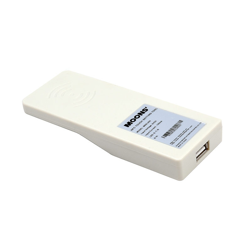
4. Essential Hardware
- Touch Setting Tool
- Double USB Ports Cable
Touch Setting Tool
Double USB Ports Cable
2
�5. Programming Steps
Step1: Connect Touch Setting Tool to PC or laptop through double USB Ports Cable.
Step2: Operate the Touch Setting Software, and Click Read to get driver’s parameters.
Step3: Let the NFC area on the Touch Setting Tool close to the NFC module on the driver.
NFC Area
NFC Module
3
�Step4: Software identifies driver and get driver’s parameters.
Step5: Modify driver’s parameters and click write.
Step6: Let the NFC area on the Touch Setting Tool close to the NFC module on the driver in order to complete
programming.
4
�6. Definition of Parameters
MOONS’ S Series 0-10V, DALI, DMX driver contains lots of excellent function. The detailed definition will be mentioned
in next words according to driver’s dimming method.
6.1 0-10V Driver
There are 4 dimming solutions integrated in one 0-10V driver. They are Tunable White, Dim to Warm, Solo Dimming, Dual
Dimming.
Dimming Port List:
Dimming Solution
Dimming Port
Tunable White
CCT Port: CCT changing; DIM Port: Intensity changing;
Channel 1 is connected to Cool LEDs, Channel 2 is connected to Warm LEDs;
Dim to Warm
DIM Port: CCT & Intensity changing;
Channel 1 is connected to Cool LEDs, Channel 2 is connected to Warm LEDs;
Solo 0-10V Dimming
DIM Port: Intensity changing;
Dual 0-10V Dimming
CCT Port: control Ch2’s intensity; DIM Port: control Ch1’s intensity;
- Tunable White: Change fixture’s color temperature and intensity via two 0-10V dimming signal respectively.
- Dim to Warm: Dim like incandescent light bulb, change fixture’s color temperature when dimmed via one 0-10V
dimming signal.
- Solo Dimming: Dim two channels on the driver via one 0-10V dimming signal simultaneously.
- Dual Dimming: Dim two channels on the driver via two 0-10V dimming signals respectively.
【General Setting】
- Current:
Set driver’s output current value. The unit is mA, the minimum adjustable unit equals 1mA.
- Dimming Strategy:
Choose dimming solution (Tunable White, Dim to Warm, Solo Dimming, Dual Dimming).
- Dimming Curve:
Set driver’s dimming curve to be linear or logarithmic.
- Maximum 0-10V Input Voltage:
Set the voltage of dimming signal at 100% intensity & coolest CCT.
The valid range: 7~10V.
e.g. If the driver’s max volt is set to be 8V.
The driver will keeps 100% intensity as long as the dimming signal’s voltage ≧8V.
The driver will keeps coldest CCT as long as the dimming signal’s voltage ≧8V.
5
�- Minimum Dimming Level:
Set driver’s minimum dimming level.
The valid range of logarithmic dimming curve: 0.1%~100%.
The valid range of linear dimming curve: 0.4%~100%, the minimum adjustable unit is 1/254;
- Fade Time:
Set the fade time of both CCT changing and Intensity changing.
The Valid range is 150~10000 ms, the minimum adjustable unit is 50ms.
If the value is set to be 800ms, driver will cost 800ms to achieve intensity B from intensity A.
Driver will cost 800ms to achieve CCT B from CCT A.
- NTC:
Set the temperature of NTC.
【Specific Setting-Tunable White】
- Physical CCT:
Set driver’s CCT range according to fixture.
The valid range: 1500-6500K.
In order to achieve accurate CCT range, please set driver’s CCT range according to fixture’s actual CCT range.
- Logical CCT:
Define the CCT range the driver can achieve. Logical CCT Range≤Physical CCT Range
【Specific Setting-Dim to Warm】
- Physical CCT:
Set driver’s CCT range according to fixture.
The valid range: 1500-3200K.In order to achieve accurate CCT range, please set driver’s CCT range according to fixture’s
actual CCT range.
- Logical CCT:
Define the CCT range the driver can achieve. Logical CCT Range≤Physical CCT Range
- Intensity Ratio:
Intensity Ratio=Warmer LED’s power ÷Cooler LED’s power
- Dim To Warm Level:
- Warmest:
The intensity level of corresponding warmest CCT.
Assume that the warmest is set to be 10%, warmest CCT (logical) is set to be 2200K.
The driver will keep CCT at 2200K as long as the intensity is≦10%.
- Coolest:
6
�The intensity level of corresponding coolest CCT.
Assume that the coolest is set to be 80%, coolest CCT (logical) is set to be 2700K.
The driver will keep CCT at 2700 as long as the intensity is ≧80%.
6.2
DALI Driver
There are 4 dimming solutions integrated in one DALI driver. They are DT8 CCT, DT6 CCT, DT6 Solo, DT6 Dual.
- DT8 CCT: achieve tunable white through 1 DALI address.
- DT6 CCT: achieve tunable white through 2 DALI addresses.
- DT6 Solo: use 1 DALI address to control two channels simultaneously.
- DT6 Dual: use 2 DALI addresses to control two channels respectively.
Dimming Port List:
Dimming Solution
Dimming Port
DT8 CCT
Channel 1 is connected to Cool LEDs, Channel 2 is connected to Warm LEDs;
【General Setting】
- Current:
Set driver’s output current value. The unit is mA, the minimum adjustable unit equals 1mA.
- Dimming Strategy:
Choose dimming solution (DT8 CCT, DT6 CCT, DT6 Solo, DT6 Dual).
- Dimming Curve:
Set driver’s dimming curve to be linear or logarithmic.
- Minimum Dimming Level:
Set driver’s minimum dimming level.
The valid range of logarithmic dimming curve: 0.1%~100%.
The valid range of linear dimming curve: 0.4%~100%, the minimum adjustable unit is 1/254;
- NTC:
Set the temperature of NTC.
- Physical CCT:
Set driver’s CCT range according to fixture.
The valid range: 1500-6600K.In order to achieve accurate CCT range, please set driver’s CCT range according to fixture’s
actual CCT range.
- Logical CCT:
Define the CCT range the driver can achieve. Logical CCT Range≤Physical CCT Range
【Specific Setting】
- Power Output Enable
Enable or disable DALI power output on the driver. 15V-100mA
7
�6.3
DMX Driver
There are 3 dimming solutions integrated in one DMX driver. They are DMX CCT, DMX Solo, DMX Dual.
- DMX CCT: achieve tunable white through two DMX addresses, one address to control CCT, another DMX address to
control intensity.
- DMX Solo: use one address to control two channels simultaneously.
- DMX Dual: use two addresses to control two channels respectively.
Dimming Port List:
Dimming Solution
Dimming Port
DMX CCT
Channel 1 is connected to Cool LEDs, Channel 2 is connected to Warm LEDs;
【General Setting】
- Current:
Set driver’s output current value. The unit is mA, the minimum adjustable unit equals 1mA.
- Dimming Strategy:
Choose dimming solution (DMX CCT, DMX Solo, DMX Dual.).
- Dimming Curve:
Set driver’s dimming curve to be linear or Gamma
- Minimum Dimming Level:
Set driver’s minimum dimming level.
The valid range of logarithmic dimming curve: 0.1%~100%.
The valid range of linear dimming curve: 0.4%~100%, the minimum adjustable unit is 1/254;
- NTC:
Set the temperature of NTC.
- DMX Start Address:
Set driver’s start address.
- Daisy Chain:
There are four operating modes of MOONS’ DMX driver. They are: Auto-addressing mode, Forwarding mode, Manual
mode, Master mode.
- Auto-addressing mode:
In the Auto-addressing mode, device may receive the necessary data from the Network start address and then gain these data.
Finally, the rest data will be transferred to the next device.
E.g. If the configuration status likes following form shows:
Device
A
Network Start address
3
Footprint
Network 8bits or 16bits
2
8
8
�Handling steps:
Step1: Device A receives the DMX512 dimming signal.
Step2: Ignore slot0, slot1, slot2 data of dimming signal.
Step3: Gain slot 3, slot 4 data of dimming signal and perform dimming. At the same time slot5-slot512 data of dimming
signal will be transferred to next device.
- Forwarding mode:
In the Forwarding mode, device may receive the necessary data from the Network start address and then gain these data.
Finally, the data will be transferred to the next device again.
E.g. If the configuration status likes following form shows:
Device
Network Start address
A
Footprint
Network 8bits or 16bits
2
8
3
Handling steps:
Step1: Device A receives the DMX512 dimming signal.
Step2: Ignore slot0, slot1,slot2 data of dimming signal.
Step3: Gain slot3,slot4 data of dimming signal and perform dimming. At the same time slot3-slot512 data of dimming signal
will be transferred to next device.
- Master mode:
In the Master mode, one device can hold 32 slaves and the number of slave can be set through this DMX driver
configuration software. Device may receive the necessary data from the Network start address and gain these data. Then the
data will transferred to the slave device through forwarding mode. The slave device won’t stop to repeat the same action
until the final slave device receives the necessary dimming signal. And then transfer the rest data to the next device.
Notes: Whatever mode device is, if it connects to the “master mode device”, it will change to be the slave of the “master
mode device” forcibly.
E.g. If the configuration status likes following form shows:
Device
Daisy-chain mode
Footprint
Network 8bits or 16bits
Network start address
A
Master
2
8bits
3
B
Slave
2
8bits
1
C
Slave
2
8bits
1
D
Auto-addressing
2
8bits
3
E
Forwarding
2
8bits
3
Assume: The Network address is set to be 3. The whole device chain will perform like following steps shows.
Handling steps:
9
�Step1: Device A receives the DMX512 dimming signal.
Step2: Ignore slot0,slot1,slot2 data of dimming signal.
Step3: Gain slot3,slot4 data of dimming signal and perform dimming. At the same time slot3-slot512 data of dimming signal
will be transferred to the device B.
Step4: Device B receives the slot3-slot512 data of dimming signal and gain slot3,slot4 data of dimming signal to perform
dimming. And then device B transfers the slot3-slot512 data of dimming signal to device C.
Step5: Device C receives the slot3-slot512 dimming signal and gain slot3,slot4 data of dimming signal to perform dimming.
Because device C is the final slave device, device C transfers the slot5-slot512 data of dimming signal to device D.
Step6: The Daisy-chain mode of device D is Auto-addressing, assume the Network start address is 3, it will gain the slot7,
slot8 data of dimming signal and perform dimming. And then it transfers slot9-slot512 data of dimming signal to device E.
- Manual mode:
In the Manual mode, device may receive the necessary data from the Network start address and then gain these data. Finally,
the original data will be transferred to the next device.
E.g. If the configuration status likes following form shows:
Device
Network Start address
A
Footprint
Network 8bits or 16bits
2
8
3
Handling steps:
Step1: Device A receives the DMX512 dimming signal.
Step2: Ignore slot0, slot1, slot2 data of dimming signal.
Step3: Gain slot 3, slot 4 data of dimming signal and perform dimming. At the same time slot1-slot512 data of dimming
signal will be transferred to next device.
- Bit Control:
Select the resolution of driver, 8 bits or 16 bits.
- Power On Level:
The intensity the driver outputs, when there is no dimming signal during starting process.
- Failure Level:
The intensity the driver outputs, when the driver loses the dimming signal.
Hold means the driver will keep the previous intensity level when the driver loses the dimming signal.
The valid range: 0~100%, Hold.
- Failure Delay Time:
Set the time to trigger Failure mode.
【Specific Setting-DMX CCT】
- Physical CCT:
10
�Set driver’s CCT range according to fixture.
The valid range: 1500-6500K.In order to achieve accurate CCT range, please set driver’s CCT range according to fixture’s
actual CCT range.
- Logical CCT:
Define the CCT range the driver can achieve. Logical CCT Range≤Physical CCT Range
- Power On CCT:
The CCT the driver achieves, when there is no dimming signal during starting process.
- Failure CCT:
The CCT the driver outputs, when the driver loses the dimming signal.
Hold means the driver will keep the previous CCT level when the driver loses the dimming signal.
The valid range: logic CCT range, Hold.
11
�