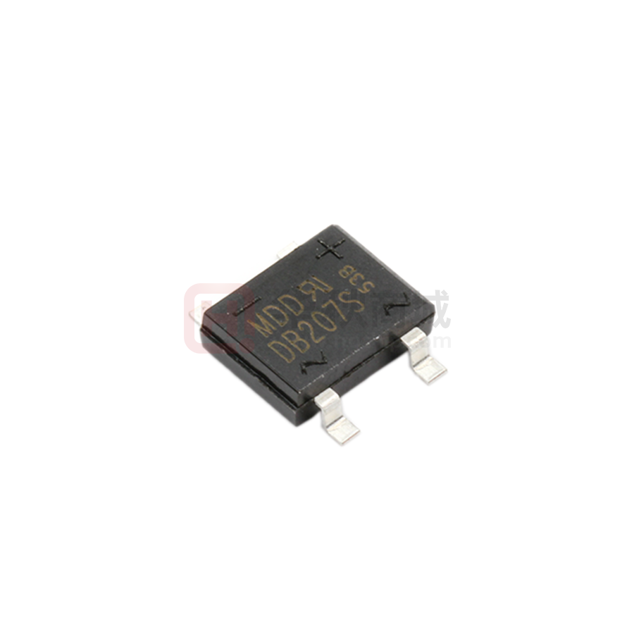
DB201S THRU DB207S
Voltage Range - 50 to 1000 Volts
Current - 1.0 Ampere
SINGLE PHASE GLASS PASSIVATED BRIDGE RECTIFIERS
Features
DBS
Ideal for printed circuit board
Reliable low cost construction utilizing molded plastic technique
.205(5.2)
High temperature soldering guaranteed: 260°/10 seconds at 5
.195(5.0)
.335(8.50)
.307(7.8)
lbs., (2.3kg) tension
+
Small size, simple installation
High surge current capability
45
.118(3.0)
.087(2.20)
.047(1.20)
.035(0.88)
(1)
(2)
-
.402(10.2)
+
.382(9.70)
Mechanical Data
.255(6.5)
.245(6.2)
.014(0.35)
.008(0.15)
Case : JEDEC DBS Molded plastic body
Terminals : Solder plated, solderable per MIL-STD-750,Method
2026
Polarity : Polarity symbol marking on case
Mounting Position : Any
Weight : 0.02 ounce, 0.4 grams
.008(0.20)
.060(1.53)
~
.002(0.05)
~
(3)
.040(1.02)
(4)
Dimensions in inches and (millimeters)
Maximum Ratings And Electrical Characteristics
Ratings at 25°C ambient temperature unless otherwisespecified.
Single phase half-wave 60Hz,resistive or inductive load,for capacitive load current derate by 20%.
Parameter
Marking Code
Maximum repetitive peak reverse voltage
Maximum RMS voltage
Maximum DC blocking voltage
Maximum average forward rectified current
at TC=40°C
Peak forward surge current,
8.3ms single half sine-wave superimposed on
rated load (JEDEC Method)
Maximum instantaneous forward voltage drop
per leg at 2A
Maximum DC reverse current
TA=25°C
at rated DC blocking voltage
TA=100°C
Operating temperature range
storage temperature range
SYMBOLS
VRRM
VRMS
VDC
MDD
DB201S
50
35
50
MDD
MDD
MDD
MDD
DB202S DB203S DB204S DB205S
100
70
100
200
140
200
400
280
400
600
420
600
MDD
MDD
DB206S DB207S
800
560
800
1000
700
1000
UNITS
V
V
V
IF(AV)
2.0
A
IFSM
50
A
VF
1.1
V
IR
10
500
µA
µA
TJ
TSTG
-55 to +150
-55 to +150
°C
°C
NOTES:DBS for surface mount package.
http://www.microdiode.com
Rev:2024A3
Page :1
�DB201S THRU DB207S
Voltage Range - 50 to 1000 Volts
Current - 1.0 Ampere
Ratings And Characteristic Curves
Average Forward Output
Current, Amperes
2.0
60Hz Resistive of
IInductive
nduc
1.0
Fig. 2 Maximum Non-repetitive Peak
Forward Surge Current
Peak Forward Surge Current,
Amperes
Fig. 1 Derating Curve for
Output Rectified Current
60
8.3ms
Single half-sine-Wave
[JEDEC Method]
50
40
30
20
10
0
1
10
100
Number of Cycles at 60HZ
Fig. 4 Typical Revers Characteristics
100
0
60
80
100
120
140
Ambient Temperature, C
Fig. 3 Typical Instantaneous
Forward Characteristics
Tj=125 C
10
1.0
Tj=25 C
0.1
.01
10
Tj=25 C
Pulse Width=300us
2% duty cycle
1.0
0
20
40
60
100
100
120
140
Tj=25 C
f=1.0MHz
Vsig =50mV
0.1
.01
0.4
80
Percent of Rated Peak Reverse
Voltage, %
Fig. 5 Typical Junction Capacitance
0.6
0.8
1.0
1.2
Instantaneous Forward
Voltage, Volts
1.4
Capacitance, pF
Instantaneous Forward Current,
Amperes
Instantaneous Reverse
Current ,Amperes
40
10
1
1.5 2
10
100
Reverse Voltage, Volts
The curve above is for reference only.
http://www.microdiode.com
Rev:2024A3
Page :2
�
很抱歉,暂时无法提供与“DB207S”相匹配的价格&库存,您可以联系我们找货
免费人工找货- 国内价格
- 10+0.55192
- 100+0.45906
- 200+0.45217
- 400+0.41273
- 1000+0.28710
- 国内价格
- 1+0.26180
- 30+0.25245
- 100+0.23375
- 500+0.21505
- 1000+0.20570