Radial Lead Resettable Polymer PTCs
SC60 Series
Description
SC60 series radial leaded PTCs are designed to provide
over-current protection for low voltage (≤60V) applications
where space is not a concern and resettable protection is
preferred.
Features
Cured, flame retardant epoxy polymer meets UL 94V-0
requirements
60V operating voltage
Fast time-to-trip
RoHS compliant, Lead-Free and Halogen-Free
Applications
USB hubs ,ports and
peripherals
Power ports
IEEE1394 ports
Motor protection
Automotive application
Computers and peripherals
General electronics
Electrical Parameters
Part Number
I hold (A)
I trip (A)
V max
(Vdc)
I max
(A)
P dtyp.
(W)
Maximum Time
To Trip
R min
(Ω)
R max
(Ω)
R 1max
(Ω)
SC60-005
0.05
0.10
60
40
0.22
0.25
5.0
7.30
SC60-010
0.10
0.20
60
40
0.38
0.50
4.0
2.50
SC60-017
0.17
0.34
60
40
0.48
0.85
3.0
2.00
SC60-020
0.20
0.40
60
40
0.41
1.00
2.2
1.50
SC60-025
0.25
0.50
60
40
0.45
1.25
2.5
1.10
SC60-030
0.30
0.60
60
40
0.49
1.50
3.0
0.80
SC60-040
0.40
0.80
60
40
0.56
2.00
3.8
0.50
SC60-050
0.50
1.00
60
40
0.77
2.50
4.0
0.45
SC60-065
0.65
1.30
60
40
0.88
3.25
5.3
0.30
SC60-075
0.75
1.50
60
40
0.92
3.75
6.3
0.25
SC60-090
0.90
1.80
60
40
0.99
4.50
7.2
0.20
SC60-110
1.10
2.20
60
40
1.50
5.50
8.2
0.15
SC60-135
1.35
2.70
60
40
1.70
6.75
9.6
0.12
SC60-160
1.60
3.20
60
40
1.90
8.00
11.4
0.09
SC60-185
1.85
3.70
60
40
2.10
9.25
12.6
0.08
SC60-200
2.00
4.00
60
40
2.10
6.00
20.0
0.08
SC60-250
2.50
5.00
60
40
2.50
12.50
15.6
0.05
SC60-300
3.00
6.00
60
40
2.80
15.00
19.8
0.04
SC60-375
3.75
7.50
60
40
3.20
18.75
24.0
0.03
SC60-500
5.00
10.00
60
40
3.20
15.00
25.0
0.025
I hold= Hold current: maximum current device will pass without tripping in 25°C still air.
I trip= Trip current: minimum current at which the device will trip in 25°C still air.
V max= Maximum voltage that can be safely placed across a device in its tripped state under specified fault conditions.
I max= Maximum fault current device can withstand without damage at rated voltage (Vmax)
Pdtyp.= Power dissipated from device when in the tripped state at 25°C still air.
R min= Minimum resistance of device in initial (un-soldered) state.
R max= Maximum resistance of device in initial (un-soldered) state.
R 1max= Maximum resistance of device at 25°C measured one hour after tripping.
Caution: Operation beyond the specified rating may result in damage and possible arcing and flame.
20.00
7.50
5.20
3.00
2.20
1.60
1.00
0.90
0.60
0.50
0.40
0.32
0.24
0.18
0.16
0.16
0.11
0.08
0.065
0.05
30.00
12.00
8.00
4.40
3.00
2.10
1.29
1.17
0.72
0.60
0.47
0.38
0.30
0.22
0.20
0.20
0.13
0.10
0.08
0.06
SOCAY Electronics Corp., Ltd.
Revision
November 03, 2017
Current
(A)
Resistance
Time
(Sec.)
www.socay.com
1/4
@ SOCAY Electronics Corp., Ltd. 2017
Specifications are subject to change without notice.
Please refer to www.socay.com for current information.
�Radial Lead Resettable Polymer PTCs
SC60 Series
Temperature Rerating Chart – I hold (A)
Ambient Operation Temperature
Part Number
-40°C
-20°C
0°C
25°C
40°C
50°C
60°C
70°C
85°C
Hold Current (A)
SC60-005
0.078
0.068
0.06
0.05
0.04
0.036
0.032
0.027
0.02
SC60-010
0.16
0.14
0.12
0.10
0.08
0.072
0.063
0.054
0.04
SC60-017
0.26
0.23
0.20
0.17
0.14
0.12
0.11
0.09
0.07
SC60-020
0.31
0.27
0.24
0.20
0.16
0.14
0.13
0.11
0.08
SC60-025
0.39
0.34
0.30
0.25
0.20
0.18
0.16
0.14
0.10
SC60-030
0.47
0.41
0.36
0.30
0.24
0.22
0.20
0.16
0.12
SC60-040
0.62
0.54
0.48
0.40
0.32
0.29
0.25
0.22
0.16
SC60-050
0.78
0.68
0.60
0.50
0.41
0.36
0.32
0.27
0.20
SC60-065
1.01
0.88
0.77
0.65
0.53
0.47
0.41
0.35
0.26
SC60-075
1.16
1.02
0.89
0.75
0.61
0.54
0.47
0.41
0.30
SC60-090
1.40
1.22
1.07
0.90
0.73
0.65
0.57
0.49
0.36
SC60-110
1.71
1.50
1.31
1.10
0.89
0.79
0.69
0.59
0.44
SC60-135
2.09
1.84
1.61
1.35
1.09
0.97
0.85
0.73
0.54
SC60-160
2.48
2.18
1.90
1.60
1.30
1.15
1.01
0.86
0.64
SC60-185
2.87
2.52
2.20
1.85
1.50
1.33
1.17
1.00
0.74
SC60-200
3.10
2.72
2.38
2.00
1.62
1.44
1.26
1.08
0.80
SC60-250
3.88
3.40
2.98
2.50
2.03
1.80
1.58
1.35
1.00
SC60-300
4.65
4.08
3.57
3.00
2.43
2.16
1.89
1.62
1.20
SC60-375
5.81
5.10
4.46
3.75
3.04
2.70
2.36
2.03
1.50
SC60-500
7.75
6.80
5.95
5.00
4.05
3.60
3.15
2.70
2.00
Temperature Rerating Curve
Average Time Current Curves
Percentage of Rated Current
1000
Time in Seconds
100
10
1
0.1
0.01
0.001
0.1
1
10
100
Temperature (°C)
Current in Amperes
A=SC60-005
B=SC60-010
C=SC60-017
D=SC60-020
E=SC60-025
F=SC60-030
G=SC60-040
H=SC60-050
I=SC60-065
J=SC60-075
K=SC60-090
L=SC60-110
M=SC60-135
N=SC60-160
O=SC60-185
P=SC60-250
Q=SC60-300
R=SC60-375
SOCAY Electronics Corp., Ltd.
Revision
November 03, 2017
www.socay.com
2/4
@ SOCAY Electronics Corp., Ltd. 2017
Specifications are subject to change without notice.
Please refer to www.socay.com for current information.
�Radial Lead Resettable Polymer PTCs
SC60 Series
Test Procedures and Requirement
Test
Test Conditions
Accept/Reject Criteria
Resistance
In still air @25±2°C
Rmin≤R≤Rmax
Hold Current
60 min, at Ihold, In still air @25±2°C
No trip
Time to Trip
Specified current, Vmax, @25±2°C
T≤Maximum Time To Trip
Trip Cycle Life
Vmax, Imax,100 cycles
No arcing or burning
Trip Endurance
Vmax,24hours
No arcing or burning
Soldering Parameters
Pre-Heating Zone
Refer to the condition recommended
by the manufacturer. Max. ramping
rate should not exceed 4°C/Sec
Soldering Zone
Max. solder temperature should not
exceed 260°C
Cooling Zone
Cooling by natural convection in air
Physical Specifications
Lead Material
Soldering Characteristics
Insulating Material
Device Labeling
0.05-0.4A Tin-plated Copper clad steel
0.5-3.75A Tin-plated Copper
Solder ability per MIL-STD-202, Method 208E
Cured, flame retardant epoxy polymer meets UL 94V-0 requirements.
Marked with ‘SC’, voltage, current rating
Part Numbering
Part Marking
SOCAY Electronics Corp., Ltd.
Revision
November 03, 2017
www.socay.com
3/4
@ SOCAY Electronics Corp., Ltd. 2017
Specifications are subject to change without notice.
Please refer to www.socay.com for current information.
�Radial Lead Resettable Polymer PTCs
SC60 Series
Dimensions
Figure1
Figure2
A
Part
Number
Figure
SC60-005
SC60-010
B
C
D
Lead (dia)
Inches
mm
Inches
mm
Inches
mm
Inches
mm
Max.
Max.
Max.
Max.
Typ.
Typ.
Max.
Max.
Figure1
0.236
6.0
0.405
10.3
0.200±0.020
5.1±0.5
0.122
Figure1
0.236
6.0
0.405
10.3
0.200±0.020
5.1±0.5
0.122
SC60-017
Figure1
0.236
6.0
0.445
11.3
0.200±0.020
5.1±0.5
SC60-020
Figure1
0.236
6.0
0.421
10.7
0.200±0.020
SC60-025
Figure1
0.236
6.0
0.445
11.3
SC60-030
Figure1
0.236
6.0
0.472
12.0
SC60-040
Figure1
0.276
7.0
0.472
SC60-050
Figure1
0.283
7.2
SC60-065
Figure1
0.346
SC60-075
Figure1
SC60-090
SC60-110
Packaging
Inches
mm
(Bulk Pack)
3.1
0.020
0.5
1000
3.1
0.020
0.5
1000
0.122
3.1
0.020
0.5
1000
5.1±0.5
0.122
3.1
0.020
0.5
1000
0.200±0.020
5.1±0.5
0.122
3.1
0.020
0.5
1000
0.200±0.020
5.1±0.5
0.122
3.1
0.020
0.5
1000
12.0
0.200±0.020
5.1±0.5
0.122
3.1
0.020
0.5
1000
0.480
12.2
0.200±0.020
5.1±0.5
0.122
3.1
0.020
0.5
1000
8.8
0.543
13.8
0.200±0.020
5.1±0.5
0.122
3.1
0.020
0.5
1000
0.374
9.5
0.570
14.5
0.200±0.020
5.1±0.5
0.122
3.1
0.020
0.5
1000
Figure1
0.421
10.7
0.618
15.7
0.200±0.020
5.1±0.5
0.122
3.1
0.020
0.5
1000
Figure2
0.480
12.2
0.618
15.7
0.200±0.020
5.1±0.5
0.122
3.1
0.031
0.8
1000
SC60-135
Figure2
0.543
13.8
0.681
17.3
0.200±0.020
5.1±0.5
0.122
3.1
0.031
0.8
1000
SC60-160
Figure2
0.614
15.6
0.772
19.6
0.200±0.020
5.1±0.5
0.122
3.1
0.031
0.8
500
SC60-185
Figure2
0.661
16.8
0.819
20.8
0.200±0.020
5.1±0.5
0.122
3.1
0.031
0.8
500
SC60-200
Figure2
0.661
16.8
0.819
20.8
0.200±0.020
5.1±0.5
0.122
3.1
0.031
0.8
500
SC60-250
Figure2
0.811
20.6
0.969
24.6
0.400±0.020
10.2±0.5
0.122
3.1
0.031
0.8
500
SC60-300
Figure2
0.933
23.7
1.091
27.7
0.400±0.020
10.2±0.5
0.122
3.1
0.031
0.8
200
SC60-375
Figure2
1.023
26.0
1.181
30.0
0.400±0.020
10.2±0.5
0.122
3.1
0.031
0.8
200
SC60-500
Figure2
1.023
26.0
1.161
29.5
0.400±0.020
10.2±0.5
0.122
3.1
0.031
0.8
200
Warning
This product should not be used in an application where the maximum interrupt voltage or maximum interrupt current in a fault
condition, Operation beyond the maximum rating or improper use may result in device damage and possible electrical arcing
and flame.
A PPTC device is not a fuse, It is a nonlinear thermistor that limits current, Because under a fault condition all PPTC devices go
into a high resistance state but not open circuit hazardous voltage may be present at PPTC.
The devices are intended for protection against occasional over-current or over-temperature fault conditions and should not be
used when repeated fault conditions or prolonged trip events.
In most application, power must be removed and the fault condition cleared in order to reset a PPTC device.
PPTC devices are not recommended to be installed in applications where the device is constrained such that its PPTC
properties are inhibited, for example in rigid potting materials or Add devices surface coating, Bundled devices ontology, which
lack adequate clearance to accommodate device expansion.
Contamination on of the PPTC material with certain silicone-based oils or some aggressive solvents can adversely impact the
performance of the devices. For example, Organic solvents to cleaning.
SOCAY Electronics Corp., Ltd.
Revision
November 03, 2017
www.socay.com
4/4
@ SOCAY Electronics Corp., Ltd. 2017
Specifications are subject to change without notice.
Please refer to www.socay.com for current information.
�
很抱歉,暂时无法提供与“SC60-185”相匹配的价格&库存,您可以联系我们找货
免费人工找货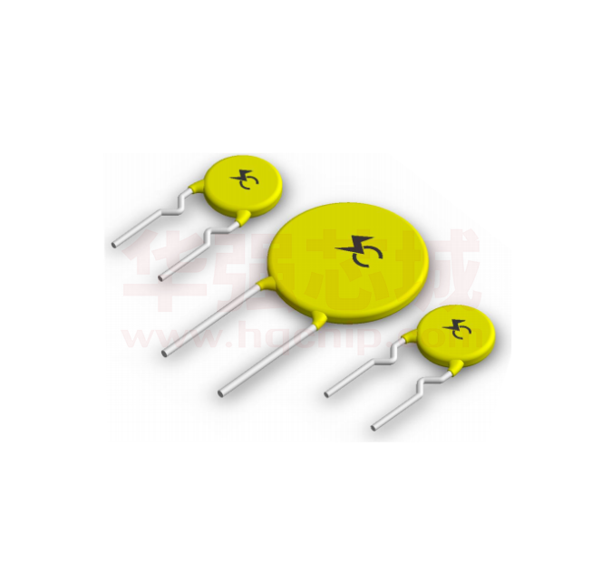


 工商网监
湘ICP备2023018690号
工商网监
湘ICP备2023018690号
