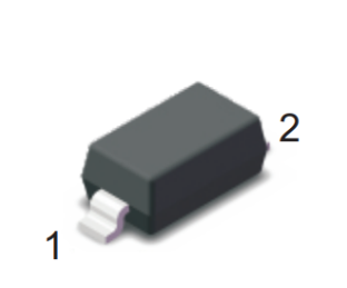
Surface Mount Transient Voltage Suppressors (TVS)
SMF Series
3.3 To 220 V
200W
Description
Uni-directional
Bi-directional
The SMF series is designed specifically to protect sensitive electronic
equipment from voltage transients induced by lightning and other transient
voltage events.
Features
Compatible with industrial standard package SOD-123
For surface mounted applications in order to optimize board space
Low leakage
Uni and Bidirectional unit
Glass passivated junction
Low inductance
Excellent clamping capability
200W Peak power capability at 10 × 1000µs waveform Repetition rate
(duty cycle):0.01%
Fast response time: typically less than 1.0ps from 0 Volts to VBR min
High Temperature soldering: 260°C/40 seconds at terminals
Typical maximum temperature coefficient ΔVBR = 0.1% ×
VBR@25°C× ΔT
Plastic package has Underwriters Laboratory Flammability 94V-0
Matte tin lead–free Plated
Halogen free and RoHS compliant
Typical failure mode is short from over-specified voltage or current
Whisker test is conducted based on JEDEC JESD201A per its table
4a and 4c
IEC-61000-4-2 ESD 15kV(Air), 8kV (Contact)
ESD protection of data lines in accordance with IEC 61000-4-2
(IEC801-2)
EFT protection of data lines in accordance with IEC 61000-4-4
(IEC801-4)
Maximum Ratings
Functional Diagram
Bi-directional
Cathode
Anode
Uni-direction
Applications
TVS devices are ideal for the protection of I/O interfaces, VCC
bus and other vulnerable circuits used in Telecom, Computer,
Industrial and Consumer electronic applications.
(TA=25℃ unless otherwise noted)
Parameter
Symbol
Value
Unit
PPPM
200
Watts
PPPM
1000
Watts
IPP
See Next Table
Amps
PM(AV)
0.4
Watt
Peak Forward Surge Current, 8.3ms Single Half Sine Wave (Note 3)
IFSM
20
Amps
Maximum Instantaneous Forward Voltage at 25A for Unidirectional Only
(Note 4)
VF
3.5
Voltage
TJ , TSTG
-55 to +150
°C
Peak Pulse Power Dissipation with a 10/1000µs waveform (Fig.1)(Note
1), (Note 2)
Peak Pulse Power Dissipation with a 8/20µs waveform (Fig.1)(Note 1),
(Note 2)
Peak Pulse Current with a 10/1000µs waveform.(Note1,Fig.3)
Power Dissipation on Infinite Heat Sink at TL=75°C
Operating junction and Storage Temperature Range.
Notes:
1. Non-repetitive current pulse, per Fig. 3 and derated above TA = 25°C per Fig. 2.
2. Mounted on 5.0mm x 5.0mm (0.03mm thick) Copper Pads to each terminal.
3. 8.3ms single half sine-wave, or equivalent square wave, Duty cycle = 4 pulses per minutes maximum.
4. VF < 3.5V for VBR < 200V and VF< 6.5V for VBR > 201V.
SOCAY Electronics Corp., Ltd.
Revision September 20, 2017
www.socay.com
1/6
@ SOCAY Electronics Corp., Ltd. 2017
Specifications are subject to change without notice.
Please refer to www.socay.com for current information.
�Surface Mount Transient Voltage Suppressors (TVS)
SMF Series
3.3 To 220 V
Electrical Characteristics
Part Number
Uni
SMF3.3A
SMF5.0A
SMF6.0A
SMF6.5A
SMF7.0A
SMF7.5A
SMF8.0A
SMF8.5A
SMF9.0A
SMF10A
SMF11A
SMF12A
SMF13A
SMF14A
SMF15A
SMF16A
SMF17A
SMF18A
SMF19A
SMF20A
SMF22A
SMF24A
SMF26A
SMF28A
SMF30A
SMF33A
SMF36A
SMF40A
SMF43A
SMF45A
SMF48A
SMF51A
SMF54A
SMF58A
SMF60A
SMF64A
SMF70A
SMF75A
SMF78A
SMF80A
SMF85A
SMF90A
SMF100A
SMF110A
SMF120A
SMF130A
SMF140A
SMF150A
SMF160A
SMF170A
SMF180A
SMF190A
SMF200A
SMF220A
Bi
—
SMF5.0CA
SMF6.0CA
SMF6.5CA
SMF7.0CA
SMF7.5CA
SMF8.0CA
SMF8.5CA
SMF9.0CA
SMF10CA
SMF11CA
SMF12CA
SMF13CA
SMF14CA
SMF15CA
SMF16CA
SMF17CA
SMF18CA
SMF19CA
SMF20CA
SMF22CA
SMF24CA
SMF26CA
SMF28CA
SMF30CA
SMF33CA
SMF36CA
SMF40CA
SMF43CA
SMF45CA
SMF48CA
SMF51CA
SMF54CA
SMF58CA
SMF60CA
SMF64CA
SMF70CA
SMF75CA
SMF78CA
SMF80CA
SMF85CA
SMF90CA
SMF100CA
SMF110CA
SMF120CA
SMF130CA
SMF140CA
SMF150CA
SMF160CA
SMF170CA
SMF180CA
SMF190CA
SMF200CA
SMF220CA
200W
(TA=25°C unless otherwise noted)
Marking
Uni
FD
FE
FG
FK
FM
FP
FR
FT
FV
FX
FZ
HE
HG
HK
HM
HP
HR
HT
HB
HV
HX
HZ
JE
JG
JK
JM
JP
JR
JT
JV
JX
JZ
XE
XG
XK
XM
XP
XR
XT
XB
XV
XX
XZ
TE
TG
TK
TB
TM
TP
TR
TT
TV
TX
TZ
Bi
—
KE
KG
KK
KM
KP
KR
KT
KV
KX
KZ
LE
LG
LK
LM
LP
LR
LT
LB
LV
LX
LZ
ME
MG
MK
MM
MP
MR
MT
MV
MX
MZ
NE
NG
NK
NM
NP
NR
NT
NB
NV
NX
NZ
PE
PG
PK
PB
PM
PP
PR
PT
PV
PX
PZ
Reverse
Stand-Off
Voltage
VRWM (V)
3.3
5.0
6.0
6.5
7.0
7.5
8.0
8.5
9.0
10.0
11.0
12.0
13.0
14.0
15.0
16.0
17.0
18.0
19.0
20.0
22.0
24.0
26.0
28.0
30.0
33.0
36.0
40.0
43.0
45.0
48.0
51.0
54.0
58.0
60.0
64.0
70.0
75.0
78.0
80.0
85.0
90.0
100.0
110.0
120.0
130.0
140.0
150.0
160.0
170.0
180.0
190.0
200.0
220.0
Breakdown
Voltage VBR(V)
@IT
MIN
MAX
6.00
5.20
7.37
7.00
6.40
6.67
7.37
7.22
7.98
7.78
8.60
8.33
9.21
8.89
9.83
9.44
10.40
10.00
11.10
11.10
12.30
12.20
13.50
13.30
14.70
14.40
15.90
15.60
17.20
16.70
18.50
17.80
19.70
18.90
20.90
20.00
22.10
21.10
23.30
22.20
24.50
24.40
26.90
26.70
29.50
28.90
31.90
31.10
34.40
33.30
36.80
36.70
40.60
40.00
44.20
44.40
49.10
47.80
52.80
50.00
55.30
53.30
58.90
56.70
62.70
60.00
66.30
64.40
71.20
66.70
73.70
71.10
78.60
77.80
86.00
83.30
92.10
86.70
95.80
88.80
97.60
94.40
104.00
100.00
111.00
111.00
123.00
122.00
135.00
133.00
147.00
144.00
159.00
155.00
171.00
167.00
185.00
178.00
197.00
189.00
209.00
200.00
220.00
211.00
232.00
224.00
247.00
246.00
272.00
Test
Current
IT (mA)
10
10
10
10
10
1
1
1
1
1
1
1
1
1
1
1
1
1
1
1
1
1
1
1
1
1
1
1
1
1
1
1
1
1
1
1
1
1
1
1
1
1
1
1
1
1
1
1
1
1
1
1
1
1
Maximum
Clamping
Voltage
VC@IPP (V)
8.0
9.2
10.3
11.2
12.0
12.9
13.6
14.4
15.4
17.0
18.2
19.9
21.5
23.2
24.4
26.0
27.6
29.2
30.6
32.4
35.5
38.9
42.1
45.4
48.4
53.3
58.1
64.5
69.4
72.7
77.4
82.4
87.1
93.6
96.8
103.0
113.0
121.0
126.0
129.0
137.0
146.0
162.0
177.0
193.0
209.0
224.0
243.0
259.0
275.0
292.0
308.0
324.0
356.0
Maximum
Peak Pulse
Current
IPP (A)
25.00
21.74
19.42
17.86
16.67
15.50
14.71
13.89
12.99
11.76
10.99
10.05
9.30
8.62
8.20
7.69
7.25
6.85
6.54
6.17
5.63
5.14
4.75
4.41
4.13
3.75
3.44
3.10
2.88
2.75
2.58
2.43
2.30
2.14
2.07
1.94
1.77
1.65
1.59
1.55
1.46
1.37
1.23
1.13
1.04
0.96
0.89
0.82
0.77
0.73
0.69
0.69
0.62
0.56
Maximum
Reverse
Leakage IR
@VRWM (μA)
600
400
400
250
100
50
25
10
5
2.5
2.5
2.5
1
1
1
1
1
1
1
1
1
1
1
1
1
1
1
1
1
1
1
1
1
1
1
1
1
1
1
1
1
1
1
1
1
1
1
1
1
1
1
1
1
1
Note:
1. Suffix 'A ' denotes 5% tolerance device. Without 'A' denotes 10% tolerance device.
2. Add suffix 'C 'or ' CA ' after part number to specify Bi-directional devices.
3. For Bi-Directional devices having VR of 10 volts and under, the IR limit is double.
SOCAY Electronics Corp., Ltd.
Revision September 20, 2017
www.socay.com
2/6
@ SOCAY Electronics Corp., Ltd. 2017
Specifications are subject to change without notice.
Please refer to www.socay.com for current information.
�Surface Mount Transient Voltage Suppressors (TVS)
SMF Series
3.3 To 220 V
200W
Ratings and Characteristic Curves (TA=25°C unless otherwise noted)
Figure 1 - Peak Pulse Power Rating Curve
Figure 2 - Pulse Derating Curve
Peak Pulse Power (PPP) or Current (IPP)
Derating in Percentage %
PPPM - Peak Pulse Power
(kW)
10
1
0.1
0.1
1
10
100
td - Pulse Width (μs)
1000
10000
Figure 3 - Pulse Waveform
Peak Value
IPPM
CJ – Junction Capacitance (pF)
IPPM - Peak Pulse Current, % IRSM
TJ=25°C
Pulse Width(td) is defined
as the point where the peak
current decays to 50% of IPPM
100
Half Value
IPPM (IPPM/2)
50
10/1000µsec. Waveform
as defined by R.E.A
40
20
0
0
25
50
75
100
125
TA-Ambient temperature(°C)
150
175
0
2.0
t - Time (ms)
3.0
Uni-directional
@zero bins
1000
Uni-directional @VRWM
100
10
1
1.0
Bi-directional
@zero bins
10000
tc
4.0
Figure 5 - Steady State Power Derating Curve
Tj=25°C
f=1.0MHz
Vsig=50mVp-p
1.0
Bi-directional @VRWM
10.0
100.0
VBR-Reverse Breakdown Voltage (V)
1000.0
Figure 6 - Maximum Non-Repetitive Surge Current
30
0.6
IFSM-Peak Forward Surge Current
(A)
PM(AV), Steady State Power Dissipation (W)
60
100000
tr=10µsec
0.5
0.4
0.3
0.2
0.1
0.0
80
Figure 4 - Typical Junction Capacitance
150
0
100
TJ=TJ max.
8.3 ms Single Half Sine-Wave
20
10
0
0
25
50
75
100
125
150
TL - Lead Temperature(°C)
175
200
SOCAY Electronics Corp., Ltd.
Revision September 20, 2017
1
10
Number of Cycles at 60Hz
100
www.socay.com
3/6
@ SOCAY Electronics Corp., Ltd. 2017
Specifications are subject to change without notice.
Please refer to www.socay.com for current information.
�Surface Mount Transient Voltage Suppressors (TVS)
SMF Series
3.3 To 220 V
200W
I-V Curve Characteristics
Uni-directional
Bi-directional
I
I
IPP
IF
VC
V
VBR VRW
R M
VF
IT
IPP
VC
C
r
i
t
i
c
a
l
IR
IT
IT
V
IR
VRW VBR VC
R
M
IPP
Z
o
n
e
T
Physical Specifications
VBR VRW
R M
Environmental Specifications
L
SOD-123 Molded Plastic over glass
t
passivated junction
o
Color band denotes cathode except
T
Bipolar
P
Matte Tin-plated leads, Solderable per
JESD22-B102D
Case
Polarity
Terminal
Temperature Cycle
JESD22-A104
Pressure Cooker
JESD22-A102
High Temp. Storage
JESD22-A103
HTRB
JESD22-A108
Thermal Shock
JESD22-A106
Soldering Parameters
Reflow Condition
Pre Heat
TP
Ramp-up
TL
Critical Zone
TL to TP
Temperature
TS(max)
Ramp-down
TS(min)
25
-Temperature Min (Ts(min))
150°C
-Temperature Max (Ts(max))
200°C
- Time (min to max) (Ts)
60 -180 Seconds
Average ramp up rate ( Liquidus Temp TL)
to peak
3°C/second max
TS(max) to TL - Ramp-up Rate
3°C/second max
Reflow
Preheat
Lead–free assembly
- Temperature (TL) (Liquidus)
217°C
- Time (min to max) (TL)
60 -150 Seconds
Peak Temperature (TP)
Time to peak temperature
(t 25℃ to peak)
Time
Time within 5°C
Temperature (tp)
SOCAY Electronics Corp., Ltd.
Revision September 20, 2017
260 +0/-5°C
of
actual
peak
20 -40 Seconds
Ramp-down Rate
6°C/second max
Time 25°C to peak Temperature (TP)
8 minutes Max
Do not exceed
280°C
www.socay.com
4/6
@ SOCAY Electronics Corp., Ltd. 2017
Specifications are subject to change without notice.
Please refer to www.socay.com for current information.
�Surface Mount Transient Voltage Suppressors (TVS)
SMF Series
3.3 To 220 V
200W
Dimensions
SOD-123
Dimensions
Millimeters
Min
Max
Min
Max
A
0.031
0.044
0.77
1.09
B
0.1
0.112
2.51
2.81
C
0.055
0.071
1.38
1.78
D
0.140
0.152
3.51
3.82
E
0.037
0.053
0.93
1.33
F
0.01
-
0.25
-
G
-
0.008
-
0.20
Cathode Band
Part Numbering
Inches
Part Marking
SMF×××CA
5% VBR VOLTAGE TOLERANCE
BI-DIRECTIONAL
VR VOLTAGE
Marking Code
Cathode Band
SERIES
Packaging
Part Number
Component
Package
Quantity
Packaging Option
Packaging
Specification
SMFXXXXX
SOD-123
3000
Tape & Reel -12mm/7″tape
EIA STD RS-481
SOCAY Electronics Corp., Ltd.
Revision September 20, 2017
www.socay.com
5/6
@ SOCAY Electronics Corp., Ltd. 2017
Specifications are subject to change without notice.
Please refer to www.socay.com for current information.
�Surface Mount Transient Voltage Suppressors (TVS)
SMF Series
3.3 To 220 V
200W
Tape and Reel Specifications
7.0
(177.8)
0.157
(4.0)
0.059 Diameter
(1.5)
0.472
(12.0)
0.36
(9.2)
0.512(13.0)
Arbor Hole Diameter
0.157
(4.0)
0.49
(12.4)
Cover tape
Direction of Feed
Dimensions are in inches
(and millimeters)
SOCAY Electronics Corp., Ltd.
Revision September 20, 2017
www.socay.com
6/6
@ SOCAY Electronics Corp., Ltd. 2017
Specifications are subject to change without notice.
Please refer to www.socay.com for current information.
�
很抱歉,暂时无法提供与“SMF6.0A”相匹配的价格&库存,您可以联系我们找货
免费人工找货