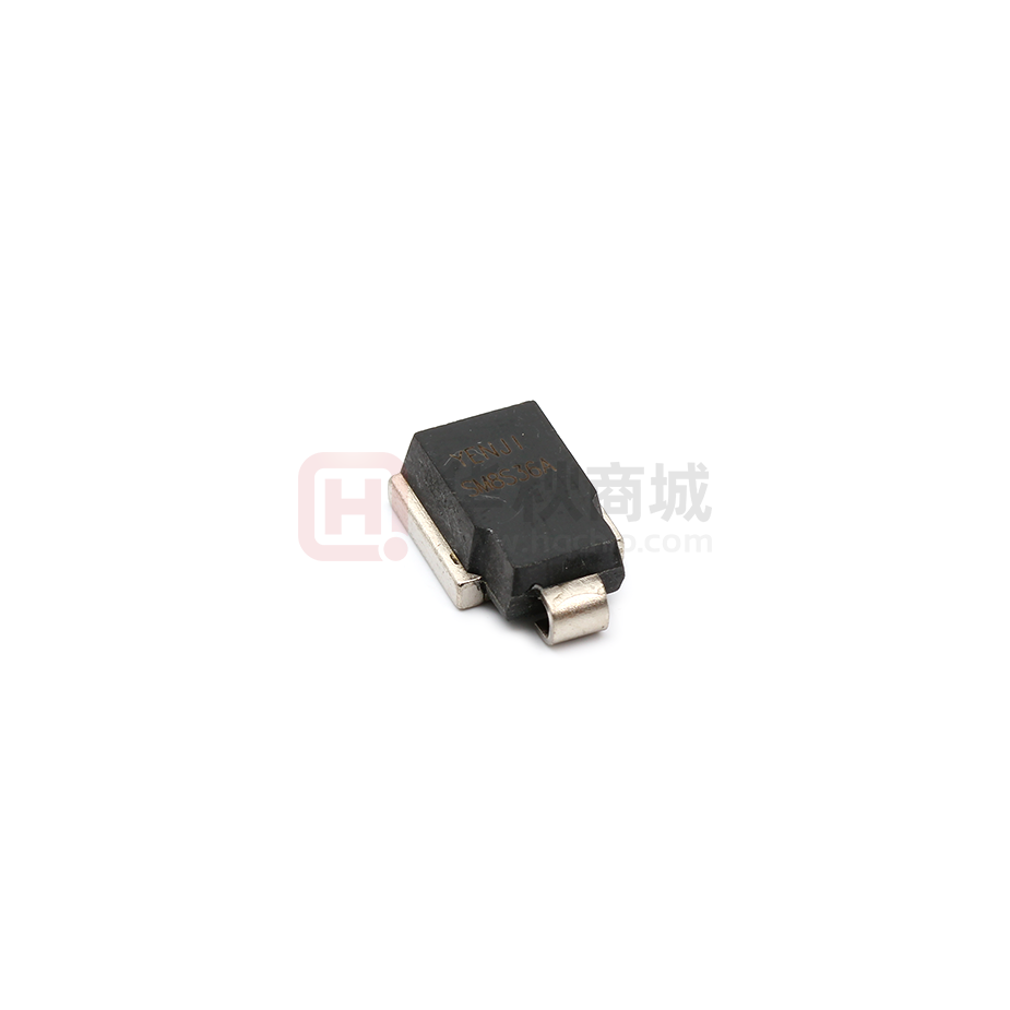
SM8S Series
Surface Mount Automotive Transient Voltage Suppressors
Stand-off Voltage 10 to 43V
Peak Pulse Power 6600W (10/1000µs)
5200W (10/10,000µs)
DO-218AB
0.628(16.0)
0.592(15.0)
0.539(13.7)
0.524(13.3)
0.116(3.0)
0.093(2.4)
Mounting Pad Layout
0.413(10.5) 0.342(8.7)
0.374(9.5) 0.327(8.3)
0.091(2.3)
0.067(1.7)
0.366(9.3)
0.343(8.7)
0.406(10.3)
0.382(9.7)
Dimensions in
inches and (millimeters)
LEAD 1
0.197(5.0)
0.185(4.7)
0.116(3.0)
0.093(2.4)
0.413(10.5)
0.374(9.5)
0.138(3.5)
0.098(2.5)
0.366(9.3)
0.343(8.7)
0.150(3.8)
0.126(3.2)
0.606(15.4)
0.583(14.8)
0.016 (0.4) Min.
LEAD 2/METAL HEATSINK
0.028(0.7)
0.020(0.5)
*Patent #’s:
0.098(2.5)
0.059(1.5)
4,980,315
5,166,769
5,278,095
Features
Mechanical Data
• Ideally suited for load dump protection
• Plastic package has Underwriters Laboratory
Flammability Classification 94V-0
• High temperature stability due to unique oxide passivation and patented PAR® construction
• Integrally molded heatsink provides a very low thermal
resistance for maximum heat dissipation
• Low leakage current at TJ = 175°C
• High temperature soldering guaranteed:
260°C for 10 seconds at terminals
• Meets ISO7637-2 surge spec.
• Low forward voltage drop
Case: Molded plastic body, surface mount with heatsink
integrally mounted in the encapsulation
Terminals: Plated, solderable per MIL-STD-750, Method 2026
Polarity: Heatsink is anode
Mounting Position: Any
Weight: 0.091 oz., 2.58 g
Packaging codes/options:
2D/750 per 13" Reel (16mm Tape),
anode towards sprocket hole, 4.5K/box
2E/750 per 13" Reel (16mm Tape),
cathode towards sprocket hole, 4.5K/box
Maximum Ratings and Thermal Characteristics (TC = 25°C unless otherwise noted)
Parameter
Symbol
Value
Unit
PPPM
6600
5200
W
PD
8.0
W
Peak pulse current with a 10/1000µs waveform
IPPM
See Table 1
A
Peak forward surge current, 8.3ms single half sine-wave
IFSM
700
A
Typical thermal resistance junction to case
RθJC
0.90
°C/W
TJ, TSTG
-55 to +175
°C
Peak pulse power dissipation with 10/1000µs waveform
10/10,000µs waveform
Steady state power dissipation
(1)
Operating junction and storage temperature range
Notes: (1) Non-repetitive current pulse derated above TA=25°C
1
�SM8S Series
Electrical Characteristics (TC = 25°C unless otherwise noted)
Device Type
SM8S10
SM8S10A
SM8S11
SM8S11A
SM8S12
SM8S12A
SM8S13
SM8S13A
SM8S14
SM8S14A
SM8S15
SM8S15A
SM8S16
SM8S16A
SM8S17
SM8S17A
SM8S18
SM8S18A
SM8S20
SM8S20A
SM8S22
SM8S22A
SM8S24
SM8S24A
SM8S26
SM8S26A
SM8S28
SM8S28A
SM8S30
SM8S30A
SM8S33
SM8S33A
SM8S36
SM8S36A
SM8S40
SM8S40A
SM8S43
SM8S43A
Breakdown Voltage
V(BR)
(V)
Test Current
IT
Stand-off
Voltage
VWM
Maximum
Reverse
Leakage
at VWM
ID
Maximum Max. Peak Maximum
Reverse
Pulse
Clamping
Leakage
Current
Voltage at
at VWM
at 10/1000µs
IPPM
Tc = 175oC Waveform
VC
Min.
Max.
(mA)
(V)
(µA)
ID(µA)
(A)
(V)
11.1
11.1
12.2
12.2
13.3
13.3
14.4
14.4
15.6
15.6
16.7
16.7
17.8
17.8
18.9
18.9
20.0
20.0
22.2
22.2
24.4
24.4
26.7
26.7
28.9
28.9
31.1
31.1
33.3
33.3
36.7
36.7
40.0
40.0
44.4
44.4
47.8
47.8
13.6
12.3
14.9
13.5
16.3
14.7
17.6
15.9
19.1
17.2
20.4
18.5
21.8
19.7
23.1
20.9
24.4
22.1
27.1
24.5
29.8
26.9
32.6
29.5
35.3
31.9
38.0
34.4
40.7
36.8
44.9
40.6
48.9
44.2
54.3
49.1
58.4
52.8
5.0
5.0
5.0
5.0
5.0
5.0
5.0
5.0
5.0
5.0
5.0
5.0
5.0
5.0
5.0
5.0
5.0
5.0
5.0
5.0
5.0
5.0
5.0
5.0
5.0
5.0
5.0
5.0
5.0
5.0
5.0
5.0
5.0
5.0
5.0
5.0
5.0
5.0
10
10
11
11
12
12
13
13
14
14
15
15
16
16
17
17
18
18
20
20
22
22
24
24
26
26
28
28
30
30
33
33
36
36
40
40
43
43
15
15
10
10
10
10
10
10
10
10
10
10
10
10
10
10
10
10
10
10
10
10
10
10
10
10
10
10
10
10
10
10
10
10
10
10
10
10
250
250
150
150
150
150
150
150
150
150
150
150
150
150
150
150
150
150
150
150
150
150
150
150
150
150
150
150
150
150
150
150
150
150
150
150
150
150
351
388
328
363
300
332
277
307
256
284
245
270
229
254
216
239
205
226
184
204
168
186
153
170
142
157
132
145
123
136
112
124
103
114
92.4
102
86.0
95.1
18.8
17.0
20.1
18.2
22.0
19.9
23.8
21.5
25.8
23.2
26.9
24.4
28.8
26.0
30.5
27.6
32.2
29.2
35.8
32.4
39.4
35.5
43.0
38.9
46.6
42.1
50.1
45.4
53.5
48.4
59.0
53.3
64.3
58.1
71.4
64.5
76.7
69.4
Note: For all types maximum VF = 1.8V at IF = 100A measured on 8.3ms single half sine-wave or equivalent square wave, duty cycle = 4 pulses per minute maximum
2
�SM8S Series
Ratings and
Characteristic Curves (TA = 25°C unless otherwise noted)
Load Dump Power Characteristics
(10ms Exponential Waveform)
Power Derating Curve
6,000
8.0
Load Dump Power (W)
Power Dissipation (W)
5,000
6.0
4.0
2.0
4,000
3,000
2,000
1,000
0
0
50
0
150
100
200
25
75
100
150
125
175
Case Temperature (°C)
Case Temperature (°C)
Pulse Waveform
Reverse Power Capability
10,000
150
tr = 10µs
Peak Value IPP
100
TA = 25°C
Pulse width (td) is defined as
the point where the peak
current decays to 50% of IPP
Half Value –
50
Reverse Surge Power (W)
Input Peak Pulse Current %
50
IPP
2
td
0
0
1,000
10
30
20
40
100
10
Pulse Width (ms) – 1/2 IPP Exponential Waveform
Time, ms (t)
Typical Transient Thermal Impedance
Transient Thermal Impedance (°C/W)
100
RΘJA
10
RΘJC
1
0.1
0.01
0.01
0.1
1
10
100
t – Pulse Width (sec.)
3
�
很抱歉,暂时无法提供与“SM8S36A”相匹配的价格&库存,您可以联系我们找货
免费人工找货