Datasheet SHT1x (SHT10, SHT11, SHT15)
Humidity and Temperature Sensor
•
•
•
•
•
Fully calibrated
Digital output
Low power consumption
Excellent long term stability
SMD type package – reflow solderable
Product Summary
Each SHT1x is individually calibrated in a precision
humidity chamber. The calibration coefficients are
programmed into an OTP memory on the chip. These
coefficients are used to internally calibrate the signals
from the sensors. The 2-wire serial interface and internal
voltage regulation allows for easy and fast system
integration. The tiny size and low power consumption
makes SHT1x the ultimate choice for even the most
demanding applications.
Dimensions
Sensor Chip
NC
NC
1
NC
3
4
A5Z
11
Material Contents
NC
NC
2.5 ±0.1
2.2 MAX
2
SHT1x is supplied in a surface-mountable LCC (Leadless
Chip Carrier) which is approved for standard reflow
soldering processes. The same sensor is also available
with pins (SHT7x) or on flex print (SHTA1).
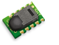
SHT1x V4 – for which this datasheet applies – features a
version 4 Silicon sensor chip. Besides a humidity and a
temperature sensor the chip contains an amplifier, A/D
converter, OTP memory and a digital interface. V4 sensors
can be identified by the alpha-numeric traceability code on
the sensor cap – see example “A5Z” code on Figure 1.
0.6 ±0.1
sensor opening
5.2 ±0.2
4.2 ±0.1
1.27 ±0.05
1.5 ±0.2 2.0 ±0.1 1.5 ±0.1
1.83 ±0.05
7.47 ±0.05
0.95 ±0.1
SHT1x (including SHT10, SHT11 and SHT15) is
Sensirion’s family of surface mountable relative humidity
and temperature sensors. The sensors integrate sensor
elements plus signal processing on a tiny foot print and
provide a fully calibrated digital output. A unique
capacitive sensor element is used for measuring relative
humidity while temperature is measured by a band-gap
sensor. The applied CMOSens® technology guarantees
excellent reliability and long term stability. Both sensors
are seamlessly coupled to a 14bit analog to digital
converter and a serial interface circuit. This results in
superior signal quality, a fast response time and
insensitivity to external disturbances (EMC).
NC
3.3 ±0.1
2.6 MAX
4.93 ±0.05
0.8 ±0.1
While the sensor is made of a CMOS chip the sensor
housing consists of an LCP cap with epoxy glob top on an
FR4 substrate. The device is fully RoHS and WEEE
compliant, thus it is free of Pb, Cd, Hg, Cr(6+), PBB and
PBDE.
Evaluation Kits
Figure 1: Drawing of SHT1x sensor packaging, dimensions in
mm (1mm = 0.039inch). Sensor label gives “11” for SHT11 as
an example. Contacts are assigned as follows: 1:GND, 2:DATA,
3:SCK, 4:VDD.
For sensor trial measurements, for qualification of the
sensor or even experimental application of the sensor
there is an evaluation kit EK-H2 available including sensor,
hard and software to interface with a computer.
For more sophisticated and demanding measurements a
multi port evaluation kit EK-H3 is available which allows for
parallel application of up to 20 sensors.
Version 4.0 – July 2008
�Datasheet SHT1x
Sensor Performance
Relative Humidity123
Parameter
Temperature45
Condition
min
0.4
8
Resolution 1
Accuracy 2
SHT11
Repeatability
Replacement
Hysteresis
%RH
±2.0
see Figure 2
%RH
±0.1
fully interchangeable
%RH
±1
%RH
±3
4.5V
0
0.1
5
MHz
VDD < 4.5V
0
0.1
1
MHz
TSCKx SCK hi/low time
100
TR/TF SCK rise/fall time
1
200
*
ns
10%
Figure 12: "Transmission Start" sequence
ns
OL = 5pF
3.5
10
20
ns
OL = 100pF
30
40
200
ns
**
**
**
ns
The subsequent command consists of three address bits
(only ‘000’ is supported) and five command bits. The
SHT1x indicates the proper reception of a command by
pulling the DATA pin low (ACK bit) after the falling edge of
the 8th SCK clock. The DATA line is released (and goes
high) after the falling edge of the 9th SCK clock.
Command
Reserved
Measure Temperature
Measure Relative Humidity
Read Status Register
Write Status Register
Reserved
Soft reset, resets the interface, clears the
status register to default values. Wait minimum
11 ms before next command
TFO
DATA fall time
TRO
DATA rise time
TV
DATA valid time
200 250
***
ns
TSU
DATA setup time
100 150
***
ns
Table 4: SHT1x list of commands
THO
DATA hold time
10
****
ns
3.3
*
TR_max + TF_max = (FSCK)-1 – TSCKH – TSCKL
**
TR0 is determined by the RP*Cbus time-constant at DATA line
***
TV_max and TSU_max depend on external pull-up resistor (RP) and total bus
line capacitance (Cbus) at DATA line
****
TH0_max < TV – max (TR0, TF0)
15
Table 3: SHT1x I/O signal characteristics, OL stands for Output
Load, entities are displayed in Figure 11.
3 Communication with Sensor
3.1 Start up Sensor
As a first step the sensor is powered up to chosen supply
voltage VDD. The slew rate during power up shall not fall
below 1V/ms. After power-up the sensor needs 11ms to
get to Sleep State. No commands must be sent before
that time.
3.2 Sending a Command
To initiate a transmission, a Transmission Start sequence
has to be issued. It consists of a lowering of the DATA line
while SCK is high, followed by a low pulse on SCK and
raising DATA again while SCK is still high – see Figure 12.
www.sensirion.com
90%
10%
Figure 11: Timing Diagram, abbreviations are explained in
Table 3. Bold DATA line is controlled by the sensor, plain DATA
line is controlled by the micro-controller. Both valid times refer to
the left SCK toggle.
Parameter
DATA
Code
0000x
00011
00101
00111
00110
0101x-1110x
11110
Measurement of RH and T
After issuing a measurement command (‘00000101’ for
relative humidity, ‘00000011’ for temperature) the
controller has to wait for the measurement to complete.
This takes a maximum of 20/80/320 ms for a 8/12/14bit
measurement. The time varies with the speed of the
internal oscillator and can be lower by up to 30%. To
signal the completion of a measurement, the SHT1x pulls
data line low and enters Idle Mode. The controller must
wait for this Data Ready signal before restarting SCK to
readout the data. Measurement data is stored until
readout, therefore the controller can continue with other
tasks and readout at its convenience.
Two bytes of measurement data and one byte of CRC
checksum (optional) will then be transmitted. The micro
controller must acknowledge each byte by pulling the
DATA line low. All values are MSB first, right justified (e.g.
the 5th SCK is MSB for a 12bit value, for a 8bit result the
first byte is not used).
Communication terminates after the acknowledge bit of
the CRC data. If CRC-8 checksum is not used the
controller may terminate the communication after the
measurement data LSB by keeping ACK high. The device
automatically returns to Sleep Mode after measurement
and communication are completed.
Version 4.0 – July 2008
6/11
�Datasheet SHT1x
Important: To keep self heating below 0.1°C, SHT1x
should not be active for more than 10% of the time – e.g.
maximum one measurement per second at 12bit accuracy
shall be made.
Status Register
Some of the advanced functions of the SHT1x such as
selecting measurement resolution, end of battery notice or
using the heater may be activated by sending a command
to the status register. The following section gives a brief
overview of these features. A more detailed description is
available in the Application Note “Status Register”.
3.4 Connection reset sequence
If communication with the device is lost the following signal
sequence will reset the serial interface: While leaving
DATA high, toggle SCK nine or more times – see Figure
13. This must be followed by a Transmission Start
sequence preceding the next command. This sequence
resets the interface only. The status register preserves its
content.
0 0 0 0 0 1 1 0
Status Register
ACK
90%
9
4-8
ACK
Bit 7
3
2
2
TS
10%
Transmission Start
Figure 14: Status Register Write
Figure 13: Connection Reset Sequence
0 0 0 0 0 1 1 1
Status Register
Checksum
ACK
10%
ACK
Bit 7
TS
90%
DATA
ACK
Bit 7
Figure 15: Status Register Read
3.5 CRC-8 Checksum calculation
The whole digital transmission is secured by an 8bit
checksum. It ensures that any wrong data can be detected
and eliminated. As described above this is an additional
feature of which may be used or abandoned.
Please consult Application Note “CRC-8 Checksum
Calculation” for information on how to calculate the CRC.
LSB
ACK
Wait for
0 0
DATA ready
0 0 0 Command
MSB
ACK
TS
Examples of full communication cycle are displayed in
Figures 15 and 16.
LSb
ACK
SCK 1
After the command Status Register Read or Status
Register Write – see Table 4 – the content of 8 bits of the
status register may be read out or written. For the
communication compare Figures 16 and 17 – the
assignation of the bits is displayed in Table 5.
Checksum
Figure 16: Overview of Measurement Sequence. TS = Transmission Start, MSB = Most Significant Byte, LSB = Last
Significant Byte, LSb = Last Significant Bit.
Transmission Start
Address = ‘000’
A2
A1
A0
C4
Command = ‘00101’
C3
C2
C1
C0
Measurement (80ms for 12bit)
ACK
SCK
DATA
A2
Idle Bits
14
13
15
12
MSb
11
10
A1
A0
9
C4
C3
C2
C1
C0
12bit Humidity Data
ACK 7
6
5
8
Sensor pulls DATA line low after
completion of measurement
ACK
4
3
2
1
LSb
0
Skip ACK to end transmission (if no CRC is used)
ACK
SCK
DATA
15
14
MSb
7
13
6
5
12
11
10
9
CRC-8 Checksum
4
3
2
1
8
ACK
LSb
0
7
6
5
ACK
Sleep (wait for next
measurement)
ACK
Skip ACK to end transmission
4
3
2
1
0
ACK
Transmission Start
SCK
DATA
7
6
5
4
3
2
1
0
Figure 17: Example RH measurement sequence for value “0000’1001“0011’0001” = 2353 = 75.79 %RH (without temperature
compensation). DATA valid times are given and referenced in boxes on DATA line. Bold DATA lines are controlled by sensor while plain
lines are controlled by the micro-controller.
www.sensirion.com
Version 4.0 – July 2008
7/11
�Datasheet SHT1x
Bit Type Description
Default
7
reserved
0
End of Battery (low voltage
No default value,
detection)
bit is only updated
6 R
X
‘0’ for VDD > 2.47
after a
‘1’ for VDD < 2.47
measurement
5
reserved
0
4
reserved
0
3
For Testing only, do not use 0
2 R/W Heater
0 off
1 R/W no reload from OTP
0 reload
’1’ = 8bit RH / 12bit Temp.
12bit RH
resolution
0 R/W
0
14bit Temp.
’0’ = 12bit RH / 14bit Temp.
resolution
Table 5: Status Register Bits
Heater: An on chip heating element can be addressed by
writing a command into status register. The heater may
increase the temperature of the sensor by 5 – 10°C12
beyond ambient temperature. The heater draws roughly
8mA @ 5V supply voltage.
For example the heater can be helpful for functionality
analysis: Humidity and temperature readings before and
after applying the heater are compared. Temperature shall
increase while relative humidity decreases at the same
time. Dew point shall remain the same.
Please note: The temperature reading will display the
temperature of the heated sensor element and not
ambient temperature. Furthermore, the sensor is not
qualified for continuous application of the heater.
4 Conversion of Signal Output
4.1 Relative Humidity
For compensating non-linearity of the humidity sensor –
see Figure 18 – and for obtaining the full accuracy of the
sensor it is recommended to convert the humidity readout
(SORH) with the following formula with coefficients given in
Table 6:
RH linear = c 1 + c 2 ⋅ SO RH + c 3 ⋅ SO RH (%RH)
2
www.sensirion.com
c2
0.0367
0.5872
c3
-1.5955E-6
-4.0845E-4
Table 6: Optimized V4 humidity conversion coefficients
The values given in Table 6 are newly introduced and
provide optimized accuracy for V4 sensors along the full
measurement range. The parameter set cx*, which has
been proposed in earlier datasheets, which was optimized
for V3 sensors, still applies to V4 sensors and is given in
Table 7 for reference.
SORH
12 bit
8 bit
c1*
-4.0000
-4.0000
c2*
0.0405
0.6480
c3*
-2.8000E-6
-7.2000E-4
For simplified, less computation intense conversion
formulas see Application Note “RH and Temperature NonLinearity Compensation”. Values higher than 99% RH
indicate fully saturated air and must be processed and
displayed as 100%RH13. Please note that the humidity
sensor has no significant voltage dependency.
100%
Relative Humidity
End of Battery function detects and notifies VDD voltages
below 2.47 V. Accuracy is ±0.05 V.
Corresponds to 9 – 18°F
c1
-2.0468
-2.0468
Table 7: V3 humidity conversion coefficients, which also apply
to V4.
Measurement resolution: The default measurement
resolution of 14bit (temperature) and 12bit (humidity) can
be reduced to 12 and 8bit. This is especially useful in high
speed or extreme low power applications.
12
SORH
12 bit
8 bit
80%
60%
40%
20%
0%
0
500
1000
1500
2000
2500
3000
3500
SORH sensor readout (12bit)
Figure 18: Conversion from SORH to relative humidity
4.2 Temperature compensation of Humidity Signal
For temperatures significantly different from 25°C (~77°F)
the humidity signal requires a temperature compensation.
The temperature correction corresponds roughly to
0.12%RH/°C @ 50%RH. Coefficients for the temperature
compensation are given in Table 8.
RH true = (T°C − 25) ⋅ (t 1 + t 2 ⋅ SO RH ) + RH linear
SORH
12 bit
8 bit
t1
0.01
0.01
t2
0.00008
0.00128
Table 8: Temperature compensation coefficients14
13
If wetted excessively (strong condensation of water on sensor surface),
sensor output signal can drop below 100%RH (even below 0%RH in some
cases), but the sensor will recover completely when water droplets
evaporate. The sensor is not damaged by water immersion or condensation.
14 Coefficients apply both to V3 as well as to V4 sensors.
Version 4.0 – July 2008
8/11
�Datasheet SHT1x
4.3 Temperature
The band-gap PTAT (Proportional To Absolute
Temperature) temperature sensor is very linear by design.
Use the following formula to convert digital readout (SOT)
to temperature value, with coefficients given in Table 9:
T = d1 + d 2 ⋅ SO T
VDD
5V
4V
3.5V
3V
2.5V
d1 (°C)
-40.1
-39.8
-39.7
-39.6
-39.4
d1 (°F)
-40.2
-39.6
-39.5
-39.3
-38.9
SOT
14bit
12bit
d2 (°C)
0.01
0.04
d2 (°F)
0.018
0.072
Table 9: Temperature conversion coefficients15.
4.4 Dew Point
SHT1x is not measuring dew point directly, however dew
point can be derived from humidity and temperature
readings. Since humidity and temperature are both
measured on the same monolithic chip, the SHT1x allows
superb dew point measurements.
For dew point (Td) calculations there are various formulas
to be applied, most of them quite complicated. For the
temperature range of -40 – 50°C the following
approximation provides good accuracy with parameters
given in Table 10:
Tn (°C)
243.12
272.62
If sensors are qualified for assemblies or devices, please
make sure that they experience same conditions as the
reference sensor. It should be taken into account that
response times in assemblies may be longer, hence
enough dwell time for the measurement shall be granted.
For detailed information please consult Application Note
“Qualification Guide”.
The SHT1x sensor series were tested according to AECQ100 Rev. F qualification test method. Sensor
specifications are tested to prevail under the AEC-Q100
temperature grade 2 test conditions listed in Table 1116.
Sensor performance under other test conditions cannot be
guaranteed and is not part of the sensor specifications.
Especially, no guarantee can be given for sensor
performance in the field or for customer’s specific
application.
Please contact Sensirion for detailed information.
Environment Standard
HTSL
125°C, 1000 hours
TC
UHST
-50°C - 125°C, 1000 cycles
Acc. JESD22-A104-C
130°C / 85%RH, 96h
THU
85°C / 85%RH, 1000h
Results17
Within
specifications
Within
specifications
Within
specifications
Within
specifications
Qualified
ESD immunity MIL STD 883E, method 3015
(Human Body Model at ±2kV)
Latch-up
force current of ±100mA with Qualified
Tamb = 80°C, acc. JEDEC 17
RH m ⋅ T
ln
+
100% Tn + T
Td (RH, T ) = Tn ⋅
RH m ⋅ T
m − ln
−
100% Tn + T
Temperature Range
Above water, 0 – 50°C
Above ice,
-40 – 0°C
5 Environmental Stability
m
17.62
22.46
Table 10: Parameters for dew point (Td) calculation.
Please note that “ln(…)” denotes the natural logarithm. For
RH and T the linearized and compensated values for
relative humidity and temperature shall be applied.
For more information on dew point calculation see
Application Note “Dew point calculation”.
Table 11: Qualification tests: HTSL = High Temperature Storage
Lifetime, TC = Temperature Cycles, UHST = Unbiased Highly
accelerated temperature and humidity Test, THU = Temperature
humidity unbiased
6 Packaging
6.1 Packaging type
SHT1x are supplied in a surface mountable LCC
(Leadless Chip Carrier) type package. The sensor housing
consists of a Liquid Crystal Polymer (LCP) cap with epoxy
glob top on a standard 0.8mm FR4 substrate. The device
is fully RoHS and WEEE compliant – it is free of of Pb, Cd,
Hg, Cr(6+), PBB and PBDE.
16
15
Temperature coefficients have slightly been adjusted compared to datasheet
SHTxx version 3.01. Coefficients apply to V3 as well as V4 sensors.
www.sensirion.com
Sensor operation temperature range is -40 to 105°C according to AEC-Q100
temperature grade 2.
17 According to accuracy and long term drift specification given on Page 2.
Version 4.0 – July 2008
9/11
�Datasheet SHT1x
Device size is 7.47 x 4.93 x 2.5 mm (0.29 x 0.19 x 0.1
inch), see Figure 1, weight is 100 mg.
6.2 Traceability Information
All SHT1x are marked with an alphanumeric, three digit
code on the chip cap (for reference: V3 sensors were
labeled with numeric codes) – see “A5Z” on Figure 1. The
lot numbers allow full traceability through production,
calibration and testing. No information can be derived from
the code directly, respective data is stored at Sensirion
and is provided upon request.
Labels on the reels are displayed in Figures 19 and 20,
they both give traceability information.
6.3 Shipping Package
SHT1x are shipped in 12mm tape at 100pcs, 400pcs and
2000pcs – for details see Figure 21 and Table 12. Reels
are individually labeled with barcode and human readable
labels.
Sensor Type
SHT10
SHT11
SHT15
Packaging
Tape & Reel
Tape & Reel
Tape & Reel
Tape & Reel
Tape & Reel
Tape & Reel
Quantity
2000
100
400
2000
100
400
Order Number
1-100218-04
1-100051-04
1-100098-04
1-100524-04
1-100085-04
1-100093-04
Table 12: Packaging types per sensor type.
Lot No.:
Quantity:
RoHS:
XX0-04-YRRRRTTTT
RRRR
Compliant
Dimensions of packaging tape is given in Figure 21. All
tapes have a minimum of 480mm empty leader tape (first
pockets of the tape) and a minimum of 300mm empty
trailer tape (last pockets of the tape).
Lot No.
Figure 19: First label on reel: XX = Sensor Type (11 for SHT11),
04 = Chip Version (V4), Y = last digit of year, RRRR = number of
sensors on reel, TTTT = Traceability Code.
Ø1.50 MIN
1.00
0.30 ± 0.05
12.00
Ø1.50 MIN
12.0 ± 0.3
5.50 ± 0.05
1.75 ± 0.10
2.00 ± 0.05
R0.3 MAX
11
A5Z
5.80
R0.5 TYP
2.80
8.20
Device Type:
Description:
1-100PPP-04
Humidity & Temperature Sensor
SHTxx
Part Order No. 1-100PPP-04 or Customer Number
Date of Delivery: DD.MM.YYYY
Order Code:
45CCCC / 0
Figure 21: Tape configuration and unit orientation within tape,
dimensions in mm (1mm = 0.039inch). The leader tape is at the
right side of the figure while the trailer tape is to the left
(direction of unreeling).
Figure 20: Second label on reel: For Device Type and Part
Order Number please refer to Table 12, Delivery Date (also
Date Code) is date of packaging of sensors (DD = day, MM =
month, YYYY = year), CCCC = Sensirion order number.
www.sensirion.com
Version 4.0 – July 2008
10/11
�Datasheet SHT1x
Revision History
Date
March 2007
August 2007
July 2008
Version
3.0
3.01
4.0
Page(s)
1 – 10
1 – 10
1 – 10
Changes
Data sheet valid for SHTxx-V4 and SHTxx-V3
Electrical characteristics added, measurement time corrected
New release, rework of datasheet
Important Notices
Warning, Personal Injury
Do not use this product as safety or emergency stop devices or in
any other application where failure of the product could result in
personal injury. Do not use this product for applications other
than its intended and authorized use. Before installing, handling,
using or servicing this product, please consult the data sheet and
application notes. Failure to comply with these instructions could
result in death or serious injury.
If the Buyer shall purchase or use SENSIRION products for any
unintended or unauthorized application, Buyer shall defend, indemnify
and hold harmless SENSIRION and its officers, employees,
subsidiaries, affiliates and distributors against all claims, costs,
damages and expenses, and reasonable attorney fees arising out of,
directly or indirectly, any claim of personal injury or death associated
with such unintended or unauthorized use, even if SENSIRION shall be
allegedly negligent with respect to the design or the manufacture of the
product.
ESD Precautions
The inherent design of this component causes it to be sensitive to
electrostatic discharge (ESD). To prevent ESD-induced damage and/or
degradation, take customary and statutory ESD precautions when
handling this product.
See application note “ESD, Latchup and EMC” for more information.
Warranty
SENSIRION warrants solely to the original purchaser of this product for
a period of 12 months (one year) from the date of delivery that this
product shall be of the quality, material and workmanship defined in
SENSIRION’s published specifications of the product. Within such
period, if proven to be defective, SENSIRION shall repair and/or
replace this product, in SENSIRION’s discretion, free of charge to the
Buyer, provided that:
•
notice in writing describing the defects shall be given to
SENSIRION within fourteen (14) days after their appearance;
•
such defects shall be found, to SENSIRION’s reasonable
satisfaction, to have arisen from SENSIRION’s faulty design,
material, or workmanship;
•
the defective product shall be returned to SENSIRION’s factory at
the Buyer’s expense; and
•
the warranty period for any repaired or replaced product shall be
limited to the unexpired portion of the original period.
This warranty does not apply to any equipment which has not been
installed and used within the specifications recommended by
SENSIRION for the intended and proper use of the equipment.
EXCEPT FOR THE WARRANTIES EXPRESSLY SET FORTH
HEREIN, SENSIRION MAKES NO WARRANTIES, EITHER EXPRESS
OR IMPLIED, WITH RESPECT TO THE PRODUCT. ANY AND ALL
WARRANTIES, INCLUDING WITHOUT LIMITATION, WARRANTIES
OF MERCHANTABILITY OR FITNESS FOR A PARTICULAR
PURPOSE, ARE EXPRESSLY EXCLUDED AND DECLINED.
SENSIRION is only liable for defects of this product arising under the
conditions of operation provided for in the data sheet and proper use of
the goods. SENSIRION explicitly disclaims all warranties, express or
implied, for any period during which the goods are operated or stored
not in accordance with the technical specifications.
SENSIRION does not assume any liability arising out of any application
or use of any product or circuit and specifically disclaims any and all
liability, including without limitation consequential or incidental
damages. All operating parameters, including without limitation
recommended parameters, must be validated for each customer’s
applications by customer’s technical experts. Recommended
parameters can and do vary in different applications.
SENSIRION reserves the right, without further notice, (i) to change the
product specifications and/or the information in this document and (ii) to
improve reliability, functions and design of this product.
Copyright© 2007, SENSIRION.
CMOSens® is a trademark of Sensirion
All rights reserved
Headquarter and Sales Offices
Headquarter
SENSIRION AG
Laubisruetistr. 50
CH-8712 Staefa ZH
Switzerland
Sales Office USA:
Phone:
+ 41 (0)44 306 40 00
Fax:
+ 41 (0)44 306 40 30
info@sensirion.com
http://www.sensirion.com/
Sales Office Korea:
SENSIRION KOREA Co. Ltd.
#1414, Anyang Construction Tower B/D,
1112-1, Bisan-dong, Anyang-city
Gyeonggi-Province
South Korea
SENSIRION Inc.
2801 Townsgate Rd., Suite 240
Westlake Village, CA 91361
USA
Phone: 805 409 4900
Fax:
805 435 0467
michael.karst@sensirion.com
http://www.sensirion.com/
Sales Office Japan:
Phone:
031 440 9925~27
Fax:
031 440 9927
info@sensirion.co.kr
http://www.sensirion.co.kr
SENSIRION JAPAN Co. Ltd.
Postal Code: 108-0074
Shinagawa Station Bldg. 7F,
4-23-5, Takanawa, Minato-ku
Tokyo, Japan
Phone: 03 3444 4940
Fax:
03 3444 4939
info@sensirion.co.jp
http://www.sensirion.co.jp
Find your local representative at: http://www.sensirion.com/reps
www.sensirion.com
Version 4.0 – July 2008
11/11
�