FS8205-DS-19_EN
Datasheet
AUG 2016
RT
P
r R ro U
ef pe NE
er rti
’
en es
ce
O
nl
y
REV. 1.9
FS8205
Fo
FO
Dual N-Channel Enhancement Mode Power MOSFET
�FS8205
Fo
FO
RT
P
r R ro U
ef pe NE
er rti
’
en es
ce
O
nl
y
Fortune Semiconductor Corporation
富晶電子股份有限公司
23F.,No.29-5, Sec. 2, Zhongzheng E. Rd.,
Danshui Dist, New Taipei City 251, Taiwan
Tel.:886-2-28094742
Fax:886-2-28094874
www.ic-fortune.com
This manual contains new product information. Fortune Semiconductor Corporation reserves the
rights to modify the product specification without further notice. No liability is assumed by Fortune
Semiconductor Corporation as a result of the use of this product. No rights under any patent
accompany the sale of the product
Rev. 1.9
2/2
�FS8205
1.
Features
1.1
Low on-resistance
1.1.1
RDS(ON) = 28 mΩ MAX. (VGS = 4.5V, ID = 4A)
1.1.2
RDS(ON) = 37 mΩ MAX. (VGS = 2.5V, ID = 3A)
Applications
3.
Li-ion battery management applications
RT
P
r R ro U
ef pe NE
er rti
’
en es
ce
O
nl
y
2.
Ordering Information
Product Number
Description
Package Type
Quantity/Reel
FS8205
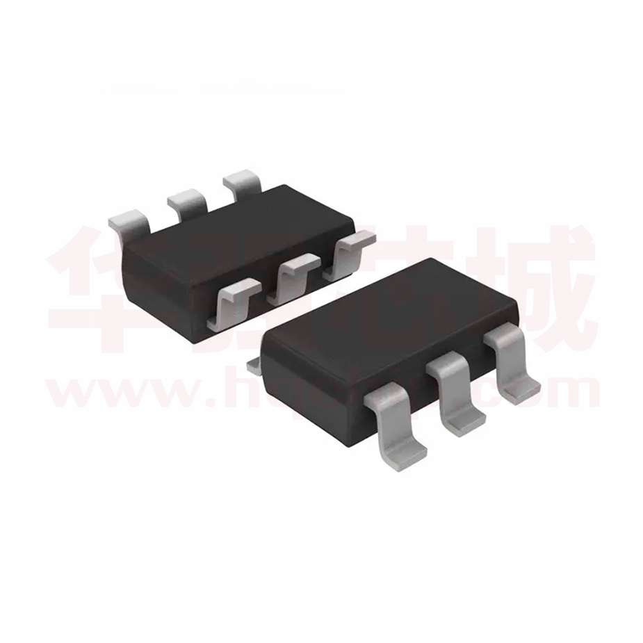
SOT23-6 package version
SOT23-6
3,000
Pin Assignment
FO
4.
For FS8205
w : A~Z or A ~ Z
Top points, bottom points & w: Lot no information
5.
Absolute Maximum Ratings
Symbol
VDS
Parameter
Rating
Units
Drain-Source Voltage
20
V
Gate-Source Voltage
±12
V
ID @TA = 25℃
Continuous Drain Current3
6
A
ID @TA = 70℃
Continuous Drain Current3
5
A
IDM
Pulsed Drain Current1
25
A
Total Power Dissipation
1
W
Fo
VGS
PD @TA = 25℃
Linear Derating Factor
0.008
W/℃
TSTG
Storage Temperature Range
-55 to 150
℃
TJ
Operating Junction Temperature Range
-55 to 150
℃
Rev. 1.9
3/3
�FS8205
6.
Thermal Data
Symbol
Parameter
Rthj-a
7.
Value
Thermal Resistance Junction-ambient3
Max.
Unit
125
℃/W
Electrical Characteristics
Electrical Characteristics @Tj = 25℃ ( unless otherwise specified )
Symbol
Parameter
Test Conditions
Min.
Typ.
Max.
Units
BVDSS
RT
P
r R ro U
ef pe NE
er rti
’
en es
ce
O
nl
y
Static Characteristics
Drain-Source Breakdown Voltage
VGS = 0V, ID = 250uA
20
-
-
V
ΔBVDSS/ΔTj
Breakdown Voltage Temperature Coefficient
Reference to 25℃, ID=1mA
-
0.1
-
V/℃
RDS(ON)
Static Drain-Source On-Resistance2
VGS = 4.5V, ID = 4A
-
23
28
mΩ
VGS = 2.5V, ID = 3A
-
30
37
mΩ
VGS(th)
IDSS
IGSS
8.
Gate Threshold Voltage
VDS = VGS, ID = 250uA
0.45
-
1.2
V
Drain-Source Leakage Current (Tj = 25℃)
VDS =16V, VGS = 0V
-
-
1
uA
Drain-Source Leakage Current (Tj = 70℃)
VDS =16V, VGS = 0V
-
-
25
uA
Gate-Source Leakage
VGS = ±10V
-
-
±0.1
uA
Min.
-
Typ.
-
Max.
0.83
1.2
Units
A
V
Source-Drain Diode
Parameter
Continuous Source Current (Body Diode)
Forward On Voltage2
Test Conditions
VD = VG = 0V, VS = 1.2V
Tj = 25℃, IS = 1.25A, VGS = 0V
FO
Symbol
IS
VSD
Notes:
Fo
1. Pulse width limited by Max. junction temperature.
2. Pulse width ≦ 300us, duty cycle ≦ 2%.
3. Surface mounted on 1 in2 copper pad of FR4 board;208℃/W when mounted on Min. copper
pad.
Rev. 1.9
4/4
�FS8205
9.
Typical Characteristics
On-Region characteristics @ Ta=25Deg
On-Region characteristics @ Ta=125Deg
25
25
15
2.5V
3.0V
10
3.5V
4.0V
5
4.5V
0
Id, Drain Current ( A )
20
2.0V
2.0V
15
2.5V
3.0V
10
3.5V
4.0V
5
RT
P
r R ro U
ef pe NE
er rti
’
en es
ce
O
nl
y
Id, Drain Current ( A )
20
4.5V
0
0
-5
0.5
1
1.5
2
0
0.5
Vds, Drain to Source Voltage ( V )
1.5
2
Vds, Drain to Source Voltage ( V )
Fig 2. Typical Output Characteristics
On-Resistance Variation with Temperature
Gate Threshold Voltage Temperature Coefficient
Vgs=4.5V, Ids=4A
Vgs=Vdg, Ids=250uA
1.4
1.4
1.2
1.2
Vth - Normalized
1
0.8
0.6
FO
0.4
1
0.8
0.6
0.4
0.2
0.2
0
0
-50
Threshold Voltage
Drain - Source On-Resistance
Fig 1. Typical Output Characteristics
Rds(on) - Normalized
1
-5
0
50
100
150
-50
0
50
100
150
Temperature ( Deg )
Temperature ( Deg )
Fig 3. Normalized On-Resistance
Fig 4. Gate Threshold Variation with
Temperature
Forward Characteristic of Rev erse Diode
2.5
2
1.5
Is (A)
Ta=25Deg
1
0.5
Fo
0
Ta=125Deg
-0.3
0.2
0.7
1.2
Vsd, Soucre to Drain Voltage ( V )
Fig 5. Forward Characteristic of Reverse Diode
Rev. 1.9
5/5
�FS8205
FO
RT
P
r R ro U
ef pe NE
er rti
’
en es
ce
O
nl
y
10. Package Information
11. Revision History
Version
1.0
1.1
1.2
1.3
1.4
1.5
Page
2009/08/17
2010/01/26
3
2010/06/02
2010/06/10
2010/08/31
2010/04/27
3
4
3
4
2011/09/08
2011/11/02
2014/05/22
2016/08/22
6
3
2
3
Description
Version 1.0 released
Rds25 TYP 28mohm MAX 36mohm
Rds45 TYP 22mohm MAX 26mohm
Rds45 TYP 23mohm MAX 27mohm
IDSS Test Conditions:VDS=16V VGS=0V
Revise Pin Assignment
Rds25 TYP:30mohm MAX:37mohm
Rds45 TYP:23mohm MAX:28mohm
VGS(th) MIN:0.45V MAX:1.2V
IGSS MAX:±0.1uA
Revise Package Outline
Revise Pin Assignment
Revised company address
Revise Package Marking Information
Fo
1.6
1.7
1.8
1.9
Date
Rev. 1.9
6/6
�
很抱歉,暂时无法提供与“FS8205”相匹配的价格&库存,您可以联系我们找货
免费人工找货