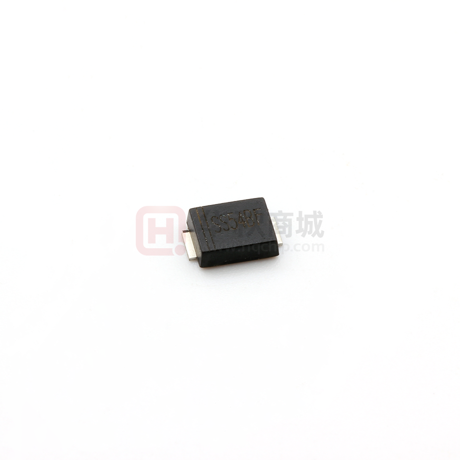
Plastic-Encapsulate Diodes
SS52BF---SS520BF
FEATURES
Cathode Band
Top View
Metal silicon junction,majority carrier conduction
For surface mounted applications
Low power loss,high efficiency
High forward surge current capability
For use in low voltage,high frequency inverters,
free wheeling,and polarity protection applicatlons
0.146(3.70)
0.138(3.50)
0.086(2.20)
0.075(1.90)
0.173(4.4)
0.165(4.2)
0.010(0.26)
0.0071(0.18)
0.051(1.30)
0.043(1.10)
0.051(1.30)
0.039(1.0)
MECHANICAL DATA
Case: JEDEC SMBF molded plastic body
Terminals: leads solderable per MIL-STD-750,
Method 2026
Mounting Position: Any
Weight:57mg/0.002oz
0.216(5.5)
0.200(5.1)
Dimensions in inches and (millimeters)
SMBF
MAXIMUM RATINGS AND ELECTRICAL CHARACTERISTICS
Ratings at 25 C ambient temperature unless otherwise specified.
Single phase half-wave 60Hz,resistive or inductive load,for capacitive load current derate by 20%.
Catalog Number
Maximum repetitive peak reverse voltage
Maximum RMS voltage
Maximum DC blocking voltage
Maximum average forward rectified current
at TL(see fig.1)
Peak forward surge current
8.3ms single half sine-wave superimposed on
rated load (JEDEC Method)
Maximum instantaneous forward voltage at 5.0A
Maximum DC reverse current
TA=25 C
at rated DC blocking voltage
TA=100 C
Typical junction capacitance (NOTE 1)
Typical thermal resistance (NOTE 2)
Operating junction temperature range
Storage temperature range
SYMBOLS SS52BF SS54BF
VRRM
VRMS
VDC
20
14
20
40
28
40
SS56BF SS58BF
60
42
60
SS510BF
80
56
80
100
70
100
SS515BF SS520BF
150
105
150
200
140
200
UNITS
VOLTS
VOLTS
VOLTS
I(AV)
5.0
Amp
IFSM
150.0
Amps
VF
0.45
IR
CJ
RθJA
TJ,
TSTG
800
0.55
0.70
0.85
1.0
50
500
40.0
-50 to +125
-50 to +150
0.95
Volts
mA
pF
C/W
C
C
Note:1.Measured at 1MHz and applied reverse voltage of 4.0V D.C.
2.P.C.B. mounted with 0.2x0.2”(5.0x5.0mm) copper pad areas
GUANGDONG HOTTECH
INDUSTRIAL CO., LTD
Page:P2-P1
�Plastic-Encapsulate Diodes
SS52BF---SS520BF
Fig.2 Typical Reverse Characteristics
Average Forward Current (A)
6.0
100LFM
5.0
4.0
3.0
2.0
Single phase half wave resistive
or inductive P.C.B mounted on
0.5×0.5"(12.7×12.7mm ) pad areas
1.0
0.0
25
50
75
100
125
150
Instaneous Reverse Current ( μA)
Fig.1 Forward Current Derating Curve
10 4
T J =100°C
10 3
10 1
T J =25°C
10 0
0
Lead Temperature (°C)
60
100
80
Fig.4 Typical Junction Capacitance
T J =25°C
Junction Capacitance ( pF)
20
10
1
SS52BF
SS54BF
SS56BF/SS58BF
SS510BF/SS520BF
0.1
0
0.5
1.0
1.5
100
SS52BF/SS54BF
SS54F/SS520F
SS56BF-SS520BF
20
10
0.1
10
1
100
Reverse Voltage (V)
Fig.5 Maximum Non-Repetitive Peak
Forward Surage Current
Fig.6- Typical Transient Thermal Impedance
150
125
100
75
50
8.3 ms Single Half Sine Wave
(JEDEC Method)
00
1
500
Instaneous Forward Voltage (V)
175
25
1000
2.0
10
Number of Cycles at 60Hz
GUANGDONG HOTTECH
100
Transient Thermal Impedance( °C /W)
Instaneous Forward Current (A)
40
20
Percent of Rated Peak Reverse Voltage(%)
Fig.3 Typical Forward Characteristic
Peak Forward Surage Current (A)
T J =75°C
10 2
100
10
1
0.01
0.1
1
10
100
t, Pulse Duration(sec)
INDUSTRIAL CO., LTD
Page:P2-P2
�
很抱歉,暂时无法提供与“SS54BF”相匹配的价格&库存,您可以联系我们找货
免费人工找货