UMW
R
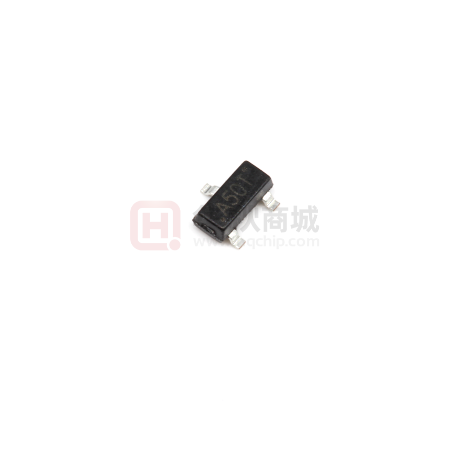
UMW SI2305A
P-Channel MOSFET
SOT–23
■ Features
● VDS (V) = -20V
● RDS(ON)<0.065 Ω (VGS = -4.5V)
● RDS(ON)<0.100 Ω (VGS = -2.5V)
● RDS(ON)<0.250 Ω (VGS = -1.8V)
1. GATE
2. SOURCE
3. DRAIN
MARKING
D
A50T
G
S
■ Absolute Maximum Ratings Ta = 25℃
Symbol
Rating
Unit
Drain-source voltage
Parameter
VDS
-20
V
Gate-source voltage
VGS
±12
V
ID
-4.2
-3.4
A
IDM
-10
A
PD
1.38
0.8
W
RθJA
90
℃/W
Tj,Tstg
-55 to +150
℃
Continuous drain current
--
TA=25℃
TA=70℃
Pulsed drain current
Power dissipation
--
TA=25℃
TA=70℃
Thermal Resistance.Junction-to-Ambient
Operating junction and storage temperature range
www.umw-ic.com
1
友台半导体有限公司
�UMW
R
UMW SI2305A
■ Electrical Characteristics Ta = 25℃
Parameter
Drain-source breakdown voltage
Gate threshold voltage
Zero gate voltage drain current
Gate-body leakage
Drain-source on-state resistance
On-state drain current
Symbol
VDSS
VGS(th)
IDSS
IGSS
rDS(on)
ID(on)
Forward transconductance
gfs
Input capacitance *
Ciss
Output capacitance *
Coss
Reverse transfer capacitance *
Crss
Total gate charge *
Qg
Testconditons
VGS = 0 V, ID = -10 μA
VDS = VGS, ID = -250 μA
Min
Typ
-20
V
VDS = -20 V , VGS = 0 V
-1
VDS = -16 V , VGS = 0 V, TJ = 55 ℃
-10
VDS = 0 V, VGS = ±12 V
±100
VGS = -4.5 V, ID = -4.2 A
0.065
VGS = -2.5 V, ID = -2.0 A
0.100
VGS = -1.8 V, ID = -1.0 A
0.250
VDS ≤ -5 V, VGS = -4.5 V
-6
VDS ≤ -5 V, VGS = -2.5 V
-3
VDS = -5 V, ID = -2.8 A
9
10.6
VDS = -16V ,VGS = -4.5 V , ID= -4.2 A
Turn-on Delay time
td(on)
5.9
Continuous source current (diode conduction) *
Diode forward voltage
VDD =-15V ,RL = 3.6Ω ,
ID = -4.2A ,V GEN =- 10V , RG = 6Ω
tf
nC
2.32
3.6
ns
32.4
2.6
IS
VSD
pF
126
3.68
Turn-off Fall time
Ω
S
167
Qgd
tr
nA
740
VDS = -15V ,VGS = 0 , f = 1 MHz
Gate-drain charge *
td(off)
μA
A
Qgs
Turn-on Reise time
Unit
V
-0.5
Gate-source charge *
Turn-off Dealy time
Max
-1.6
IS = -1.2 A, VGS = 0 V
A
-1.2
V
* Pulse test: PW ≤ 300 μs duty cycle ≤ 2%.
www.umw-ic.com
2
友台半导体有限公司
�UMW
R
UMW SI2305A
■ Typical Characteristics
Output Characteristics
Transfer Characteristics
12
12
VGS = 4.5 thru 2.5 V
TC = –55�C
2V
10
10
I D – Drain Current (A)
I D – Drain Current (A)
25�C
8
6
1.5 V
4
2
8
125�C
6
4
2
1, 0.5 V
0
0
0
0.5
1.0
1.5
2.0
2.5
3.0
3.5
0
4.0
0.5
VDS – Drain-to-Source Voltage (V)
1.0
2.5
Capacitance
On-Resistance vs. Drain Current
2000
0.25
1600
C – Capacitance (pF)
r DS(on) – On-Resistance ( � )
2.0
VGS – Gate-to-Source Voltage (V)
0.30
0.20
0.15
VGS = 1.8 V
0.10
VGS = 2.5 V
Ciss
1200
800
Coss
400
0.05
Crss
VGS = 4.5 V
0
0
0
2
4
6
10
8
0
12
2
6
4
8
VDS – Drain-to-Source Voltage (V)
ID – Drain Current (A)
On-Resistance vs. Junction Temperature
Gate Charge
1.4
5
VDS = 4 V
ID = 3.5 A
4
r DS(on) – On-Resistance (�)
(Normalized)
V GS – Gate-to-Source Voltage (V)
1.5
3
2
1
0
0
2
4
6
8
1.2
1.0
0.8
0.6
–50
10
Qg – Total Gate Charge (nC)
www.umw-ic.com
VGS = 4.5 V
ID = 3.5 A
–25
0
25
50
75
100
125
150
TJ – Junction Temperature (�C)
3
友台半导体有限公司
�UMW
R
UMW SI2305A
Source-Drain Diode Forward Voltage
On-Resistance vs. Gate-to-Source Voltage
0.5
30
TJ = 150�C
TJ = 25�C
1
0.4
r DS(on) – On-Resistance ( W )
I S – Source Current (A)
10
0.3
0.2
ID = 3.5 A
0.1
0
0.1
0.00
0.2
0.4
0.6
0.8
1.0
0
1.2
VSD – Source-to-Drain Voltage (V)
2
6
8
VGS – Gate-to-Source Voltage (V)
Single Pulse Power
Threshold Voltage
0.4
12
ID = 250 mA
0.3
10
8
0.2
Power (W)
V GS(th) Variance (V)
4
0.1
6
0.0
4
TA = 25�C
2
–0.1
–0.2
–50
0
–25
0
25
50
75
100
125
150
0.01
0.1
1
TJ – Temperature (�C)
10
100
500
Time (sec)
Normalized Thermal Transient Impedance, Junction-to-Ambient
2
1
Normalized Effective Transient
Thermal Impedance
Duty Cycle = 0.5
0.1
0.2
Notes:
0.1
PDM
0.05
t1
t2
1. Duty Cycle, D =
t1
t2
2. Per Unit Base = RthJA = 130�C/W
0.02
3. TJM – TA = PDMZthJA(t)
4. Surface Mounted
Single Pulse
0.01
10–4
10–3
10–2
10–1
1
10
100
500
Square Wave Pulse Duration (sec)
www.umw-ic.com
4
友台半导体有限公司
�
很抱歉,暂时无法提供与“UMW SI2305A”相匹配的价格&库存,您可以联系我们找货
免费人工找货