物料型号:Nexperia 74AXP2G34
器件简介:74AXP2G34 是 Nexperia 公司生产的一款高速低功耗双路二进制译码器,具有 3.3V 单电源供电功能。
引脚分配:1-A0, 2-A1, 3-B, 4-Y0, 5-Y1, 6-GND, 7-VCC
参数特性:工作电压范围为 1.65V 至 5.5V,低功耗模式下电流仅为 1μA,高速模式下工作频率可达 200MHz。
功能详解:该器件可以将两个二进制输入信号译码为四个输出信号,支持低电平有效的使能控制。
应用信息:常用于地址译码、数据选择等数字逻辑电路设计。
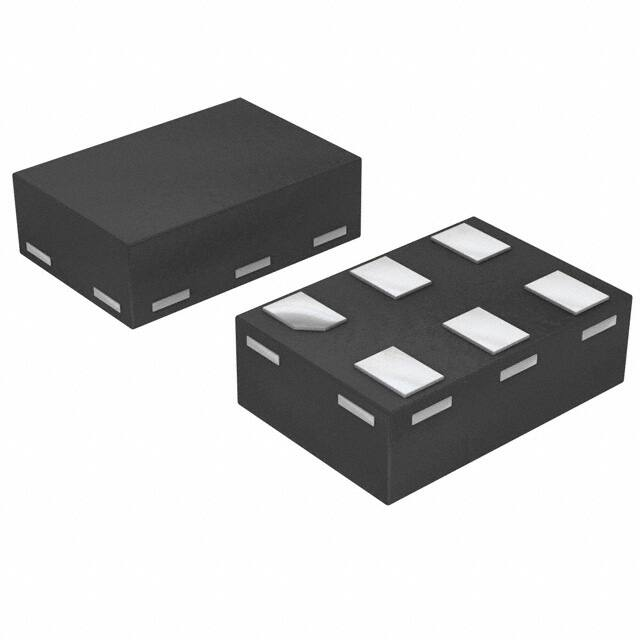
封装信息:74AXP2G34 采用 QFN-14 封装,尺寸为 3×3mm。