0
登录后你可以
  • 下载海量资料
  • 学习在线课程
  • 观看技术视频
  • 写文章/发帖/加入社区
会员中心
创作中心
发布
  • 发文章

  • 发资料

  • 发帖

  • 提问

  • 发视频

创作活动
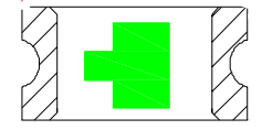
EC02-0603QGC/E

EC02-0603QGC/E

  • 厂商:

    BRTLED(佰鸿)

  • 封装:

    0603

  • 描述:

    LED 黄绿 0603 波长566~576nm 光强35mcd 正贴

  • 详情介绍
  • 数据手册
  • 价格&库存
EC02-0603QGC/E 数据手册
EVER BRIGHT OPTOELECTRONICS CORP. EC02-0603QGC/E ● Features: ●Package Dimensions: 1. Emitted Color : Super Yellow Green 2. Lens Appearance : Water Clear. 3. Mono-color type. Cathode 4. 1.6x0.8x0.8mm(0603) standard package. Anode 5. Suitable for all SMT assembly methods. 6. Compatible with infrared and vapor phase reflow solder process. 7. Compatible with automatic placement equipment. 8. This product doesn’t contain restriction Substance, comply ROHS standard. NOTES: 1.All dimensions are in millimeters (inches). 2.Tolerance is ±0.10mm (0.004”) unless otherwise specified. 3.Specifications are subject to change without notice. ● Applications: 1. Automotive : Dashboards, stop lamps, turn signals. 2. Backlighting : LCDs, Key pads advertising. 3. Status indicators : Comsumer & industrial electronics. 4. General use. ● Absolute Maximum Ratings(Ta=25℃) Parameter Symbol Rating Unit Power Dissipation Pd 50 mW Forward Current IF 20 mA Peak Forward Current *1 IFP 100 mA Reverse Volage VR 5 V Operating Temperature Topr -40℃~85℃ - Storage Temperature Tstg -40℃~85℃ - Soldering Temperature Tsol See Page6 - *1 Condition for IFP is pulse of 1/10 duty and 0.1msec width. Tel:0755-83688488 Fax:83688688 E-mail:726405362@qq.com Ver.1.0 Page 1 of 8 EVER BRIGHT OPTOELECTRONICS CORP. EC02-0603QGC/E ● Electrical and optical characteristics(Ta=25℃) Parameter Symbol Condition Min. Typ. Max. Unit Forward Voltage Vf IF=20mA - 2.2 2.6 V Luminous Intensity Iv IF=20mA 18.5 35 - mcd Reverse Current IR VR=5V - - 100 µA Peak Wave Length λp IF=20mA - 570 - nm Dominant Wave Length λd IF=20mA 566 576 nm Spectral Line Half-width Δλ IF=20mA - 30 - nm Veiwing Angle 2θ1/2 IF=20mA - 120 - deg ● Typical Electro-Optical Characteristics Curves Fig.2 Forw ard c urrent derating curve v s . am bient temperature Fig.1 R elativ e intens ity vs. wavelength 1 .0 50 Forward current (mA) Relative radiant intensity 40 0 .5 30 20 10 0 520 570 0 620 20 W av elength (nm) 100 3 .0 50 2 .5 30 20 10 1 2 3 4 2 .0 (Normalized @20mA) Relative Luminous intensity 40 Forward current (mA) 80 60 Fig.4 Relativ e lum inous intensity vs. am bient tem perature Fig.3 Forward c urrent v s. forward voltage 0 40 Amb ie nt tempe ra tu re Ta( C) 1 .5 1 .0 0 .5 0 -40 5 -20 0 40 20 60 Amb A ie nt tempe ra tu re Ta( C) Forw ard v oltage(V) Fig.6 Radiation diagram Fig.5 Relativ e lum inous intensity vs. forward current 0 10 20 2 .0 1 .5 Relative radiant intensity Relative luminous intensity (@20mA) 30 1 .0 0 .5 40 1 .0 0 .9 50 0 .8 60 70 0 .7 80 90 0 10 20 30 40 50 0 .5 0 .3 0 .1 0 .2 0 .4 0 .6 Forw ard c urrent (mA) Tel:0755-83688488 Fax:83688688 E-mail:726405362@qq.com Ver.1.0 Page 2 of 8 EVER BRIGHT OPTOELECTRONICS CORP. EC02-0603QGC/E ● Tapping and packaging specifications(Units: mm) Quantity:1000-4000PCS CATHODE 8.0 ± 0.3 ANODE USER DIRECTION OF FEED ●Package Method:(unit:mm)Vacuum 12 bag/box 4000 pcs/reel 200 Bar Code Label 245 220 Aluminum Foil Bag 220 185 645 6 box/carton 210 470 Tel:0755-83688488 Fax:83688688 E-mail:726405362@qq.com Ver.1.0 Page 3 of 8 EVER BRIGHT OPTOELECTRONICS CORP. EC02-0603QGC/E ● Bin Limits I n t e n s i t y B i n L i m i ts ( A t 2 0 m A ) BIN CODE Min. (mcd) Max. (mcd) L 18.5 28 M 28 42 N 42 63 P 63 94 To l e r a n c e f o r e a c h B i n l i m i t i s ± 1 5 % . C o l o r B i n L i m i ts ( A t 2 0 m A ) BIN CODE Min. (nm) Max. (nm) 4 566 568 5 568 570 6 570 572 7 572 574 8 574 576 To l e r a n c e f o r e a c h B i n l i m i t i s ± 1 n m . V F B i n L i m i ts ( A t 2 0 m A ) BIN CODE Min.(v) Max.(v) B 1.8 2.0 C 2.0 2.2 D 2.2 2.4 E 2.4 2.6 To l e r a n c e f o r e a c h B i n l i m i t i s ± 0 . 0 5 ● B IN: x x x VF BIN CODE Color BIN CODE Intensity BIN CODE Tel:0755-83688488 Fax:83688688 E-mail:726405362@qq.com Ver.1.0 Page 4 of 8 EVER BRIGHT OPTOELECTRONICS CORP. EC02-0603QGC/E ● Reliability Test Classification Endurance Test Environmental Test Test Item Reference Standard MIL-STD-750D:1026 Operation Life MIL-STD-883D:1005 JIS-C-7021 :B-1 High Temperature MIL-STD-202F:103B High Humidity JIS-C-7021 :B-11 Storage High MIL-STD-883:1008 Temperature JIS-C-7021 :B-10 Storage Low Temperature JIS-C-7021 :B-11 Storage MIL-STD-202F:107D Temperature MIL-STD-750D:1051 Cycling MIL-STD-883D:1010 JIS-C-7021 :A-2 MIL-STD-202F:107D(1980) Thermal Shock MIL-STD-750D:1051(1995) MIL-STD-883D:1011(1991) Test Conditions Result Ta: Under room temperature Test time:1,000hrs IF=Product Recommended IF Ta:85±5℃ RH:90%-95% Test time:240hrs Ta:100±5℃ Test time:1,000hrs 0/32 0/32 0/32 Ta: -40±5℃ Test time=1,000hrs 0/32 Ta:-35±5℃~25±5℃~85±5℃~25±5℃ 30min 5min 30min 5min 0/32 Ta:-40±5℃ ~+85±5℃ 10min 10 min Time: 20min/cycle 10cycle 0/32 Wetting balance MIL-STD-883:2003 MIL-STD-202F:208D MIL-STD-883D:2003 Ta:230±5℃ Time:5±0.5s 0/32 Solder Resistance MIL-STD-202F:210A MIL-STD-883D:1011 JIS-C-7021 :A-1 Ta:260±10℃ Time:10±1s 0/32 ● Judgment criteria of failure for the reliability Measuring items Forward voltage Reverse current Luminous intensity Note: Symbol VF ( V) IR(uA) Iv ( mcd ) Measuring conditions IF=20mA VR=5V IF=20mA Judgement criteria for failure Initial Level*1.1 Over U*2 Initial Level*0.7 1.U means the upper limit of specified characteristics. 2. Measurment shall be taken between 2 hours and after the test pieces have been returned to normal ambient conditions after completion of each test. Tel:0755-83688488 Fax:83688688 E-mail:726405362@qq.com Ver.1.0 Page 5 of 8 EVER BRIGHT OPTOELECTRONICS CORP. EC02-0603QGC/E ●IR-Reflow Soldering 260℃ Max. 10sec.Max. Above255℃ 30sec.Max. 3℃/sec.Max. 6℃/sec.Max. Above 217℃ 60~150sec. Pre-heating 150~200℃ 60~120sec. 1. Avoid any external stress applied to the resin while the LEDs are at high temperature, especially during soldering . 2. Avoid rapid cooling or any excess vibration during temperature ramp-down process 3. Although the soldering condition is recommended above, soldering at the lowest possible temperature is feasible for the LEDs Tel:0755-83688488 Fax:83688688 E-mail:726405362@qq.com Ver.1.0 Page 6 of 8 EVER BRIGHT OPTOELECTRONICS CORP. EC02-0603QGC/E ● Dip Soldering TEMPERATURE( °C) 300 Max:260℃,5sec. Suggest:2~3sec. 250 200 150 100 Fluxing 50 30 Preheat 10 20 30 40 50 60 70 80 90 100 110 120 TIME(sec.) 1. Please avoid any external stress applied to the lead-frames and epoxy while the LEDs are at high temperature,especially during soldering 2. DIP soldering and hand soldering should not be done more than one time. 3. After soldering, avoid the epoxy lens from mechanical shock or vibration until the LEDs are back to room temerature. 4. Avoid rapid cooling during temperature ramp-down process 5. Although the soldering condition is recommended above, soldering at the lowest possible temperature is feasible for the LEDs ● IRON Soldering 300℃ Within 3 sec.,One time only. Tel:0755-83688488 Fax:83688688 E-mail:726405362@qq.com Ver.1.0 Page 7 of 8 EVER BRIGHT OPTOELECTRONICS CORP. EC02-0603QGC/E ● Notes for designing: Care must be taken to provide the current limiting resistor in the circuit so as to drive the BRIGHT LEDs within the rated figures. Also, caution should be taken not to overload BRIGHT LEDs with instantaneous voltage at the turning ON and OFF of the circuit. When using the pulse drive care must be taken to keep the average current within the rated figures. Also, the circuit should be designed so as be subjected to reverse voltage when turning off the BRIGHT LEDs. ● Storage: In order to avoid the absorption of moisture, it is recommended to solder BRIGHT LEDs as soon as possible after unpacking the sealed envelope. If the envelope is still packed, to store it in the environment as following: (1) Temperature : 5℃-30℃(41℉)Humidity : RH 60﹪Max. (2) After this bag is opened, devices that will be applied to infrared reflow, vapor-phase reflow, or equivalent soldering process must be: a. Completed within 168hours. b. Stored at less than 30% RH. (3) Devices require baking before mounting, if: (2) a or (2) b is not met. (4) If baking is required, devices must be baked under below conditions: 48 hours at 60℃±3℃. ● Package and Label of Products: (1) Package: Products are packed in one bag of 4000 pcs (one taping reel) and a label is attached on each bag. (2) Label: EVER BRIGHT LOGO Part No. Quantity BIN. Sealing Date x xx xx Year Month xx Day Manufacture Location Tel:0755-83688488 Fax:83688688 E-mail:726405362@qq.com Ver.1.0 Page 8 of 8
EC02-0603QGC/E
物料型号为EC02-0603QGC/E,是EVER BRIGHT OPTOELECTRONICS CORP.生产的一款发光二极管产品。

以下是该产品的主要信息:

器件简介: - 发射颜色:超黄绿色 - 透镜外观:水清 - 单色类型 - 标准封装尺寸:1.6x0.8x0.8mm(0603) - 适用于所有SMT装配方法 - 兼容红外和蒸汽相回流焊工艺 - 兼容自动放置设备 - 产品不含限制物质,符合ROHS标准

引脚分配: - 阴极(Cathode) - 阳极(Anode)

参数特性: - 绝对最大额定值(Ta=25℃) - 功率耗散:50mW - 正向电流:20mA - 峰值正向电流:100mA(在1/10占空比和0.1ms宽度的脉冲条件下) - 反向电压:5V - 工作温度:-40°C至85°C - 存储温度:-40°C至85°C - 焊接温度:详见第6页

功能详解: - 正向电压:在20mA电流下,典型值为2.2V至2.6V - 发光强度:在20mA电流下,最小值为18.5mcd,典型值为35mcd - 反向电流:在5V反向电压下,最大值为100nA - 峰值波长:在20mA电流下,典型值为570nm - 主要波长:在20mA电流下,范围为566nm至576nm - 光谱线半宽:在20mA电流下,典型值为30nm - 视场角度:在20mA电流下,典型值为120度

应用信息: - 汽车:仪表盘、停车灯、转向灯 - 背光:LCD、键盘、广告牌 - 状态指示器:消费和工业电子 - 一般用途

封装信息: - 封装方法:真空包装,每卷4000片,每盒6卷,每箱6盒 - 包装规格:1000-4000PCS

此外,文档还包含了产品的颜色和电压分选限制、可靠性测试结果、焊接和存储建议等详细信息。
EC02-0603QGC/E 价格&库存

很抱歉,暂时无法提供与“EC02-0603QGC/E”相匹配的价格&库存,您可以联系我们找货

免费人工找货
EC02-0603QGC/E
  •  国内价格
  • 1+0.36646
  • 100+0.34203
  • 300+0.31760
  • 500+0.29317
  • 2000+0.28095
  • 5000+0.27362

库存:0