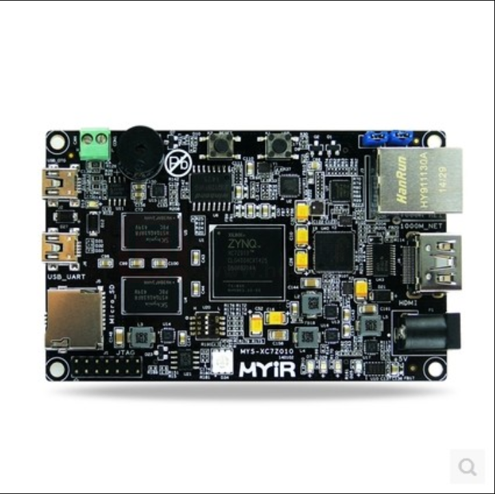
Z-turn Board
667MHz Xilinx XC7Z010/20 Dual-core ARM Cortex-A9 Processor with Xilinx 7-series FPGA logic
1GB DDR3 SDRAM (2 x 512MB, 32-bit), 16MB SPI Flash
USB_UART, USB2.0 OTG, 1 x 10/100/1000Mbps Ethernet, CAN, HDMI, TF, …
Onboard Three-axis Acceleration Sensor and Temperature Sensor
Ready-to-Run Linux Single Board Computer
Figure 1-1 Z-turn Board
The Z-turn Board is a low-cost and high-performance Single Board Computer (SBC) built around the Xilinx
Zynq-7010 (XC7Z010-1CLG400C) or Zynq-7020 (XC7Z020-1CLG400C) All Programmable System-on-Chip
(SoC) which is among the Xilinx Zynq-7000 family, featuring integrated dual-core ARM Cortex-A9 processor
with Xilinx 7-series Field Programmable Gate Array (FPGA) logic.
The Z-turn Board takes full features of the Zynq-7010 or 7020 SoC, it has 1GB DDR3 and 16MB SPI Flash on
board and a set of rich peripherals including USB-to-UART, Mini USB OTG, 10/100/1000Mbps Ethernet,
CAN, HDMI, TF, JTAG, Buzzer, G-sensor and Temperature sensor. On the rear of the board, there are two
1.27mm pitch 80-pin SMT female connectors to allow the availability of 96 (for 7010) or 106 (for 7020)
user I/O and configurable as up to 39 LVDS pairs I/O.
1/9
�The Z-turn Board is capable of running Linux operating system. MYIR has provided Linux 3.15.0 SDK, the
kernel and many drivers are in source code. The board is delivered with complete accessory kit including
two USB cables, one Ethernet cable, one HDMI cable, one 4GB TF card and one 5V power adapter and
product CD-ROM which enables you to start the development quickly when getting the board
out-of-the-box.
The Z-turn Board is an excellent development platform for evaluating and prototyping for Zynq-7000 SoC.
It can also be used as a System-on-Module (SOM) for your next embedded design; typical applications are
Industrial Automation, Test & measurement, Medical Equipment, Intelligent Video Surveillance, Aerospace
and military, etc.
Hardware Specification
The Zynq-7000 AP SoC leverages the 28nm scalable optimized programmable logic used in Xilinx’s 7 series
FPGAs. Each device is designed to meet unique requirements across many use cases and applications. The
Z-7010, Z-7015, and Z-7020 leverage the Artix®-7 FPGA programmable logic and offer lower power and
lower cost for high-volume applications. The Z-7030, Z-7035, Z-7045, and Z-7100 are based on
the Kintex®-7 FPGA programmable logic for higher-end applications that require higher performance and
high I/O throughput.
Figure 1-2 ZYNQ-7000 Device Family
2/9
�The Z-turn Board is based on the Xilinx Zynq-7010 or 7020 SoC and the hardware specification is as listed
in following table 1-1:
Item
Features
SoC
Xilinx XC7Z010-1CLG400C (Zynq-7010) or XC7Z020-1CLG400C (Zynq-7020)
- Up to 667MHz ARM® dual-core Cortex™-A9 MPCore processor
- Integrated Artix-7 class FPGA subsystem
with 28K logic cells, 17,600 LUTs, 80 DSP slices (for XC7Z010)
with 85K logic cells, 53,200 LUTs, 220 DSP slices (for XC7Z020)
- NEON™ & Single / Double Precision Floating Point for each processor
- Supports a Variety of Static and Dynamic Memory Interfaces
Memory
Storage
Communications
Display
User I/O
Dimensions
Power supply
Others
1GB DDR3 SDRAM (2 x 512MB, 32-bit)
16MB SPI Flash
512MB Nand Flash (reserved)
TF card interface
1 x 10/100/1000M Ethernet
1 x CAN
1 x Mini USB2.0 OTG
1 x USB-UART debug interface
1 x HDMI (supports 1080p resolution)
Brought out via two 1.27mm pitch 80-pin SMT female connectors
- 90/106 user I/O (7010/7020)
- Configurable 33/ 39 LVDS pairs I/O (7010/7020)
63mm x 102mm x 1.6mm (8-layer PCB design)
USB power supply or DC 5V/2A
Onboard three-axis acceleration sensor and temperature sensor
1 x 2.54mm pitch 14-pin JTAG interface
2 x Buttons (1x Reset, 1 x User)
4-channel toggle switch
5 x LEDs (3 x User LEDs, 1 x Power indicator, 1 RGB LED)
1 x Buzzer
Table 1-1 Z-turn Board Hardware Specification
3/9
�Figure 1-3 Z-turn Board (Top-view)
Figure 1-4 Z-turn Board (Bottom-view)
On the rear of the board, there are two 1.27mm pitch 80-pin SMT female connectors to allow the availability
of 96 (for 7010) or 106 (for 7020) user I/O and configurable as up to 39 LVDS pairs I/O. The Pinouts
information is as below:
4/9
�Default
Function
BGA
Pin Name
CN1
VDD_5V
1
2
VDD_3.3V
3
4
VDD18_KEY_BACKUP
5
6
7
8
V7
IO_L11P_T1_13
IO_L11N_T1_13
9
10
11
12
U10
IO_L12P_T1_13
IO_L12N_T1_13
13
14
15
16
Y7
VDDIO_13_PL
17
18
Y6
IO_L13P_T2_13
IO_L13N_T2_13
19
20
21
22
W8
IO_L15P_T2_13
IO_L15N_T2_13
23
24
25
26
T12
GND
27
28
U12
IO_L2P_T0_34
IO_L2N_T0_34
29
30
31
32
W13
IO_L4P_T0_34
IO_L4N_T0_34
33
34
35
36
P14
GND
37
38
R14
IO_L6P_T0_34
IO_L6N_T0_34
39
40
41
42
Y14
IO_L8P_T1_34
IO_L8N_T1_34
43
44
45
46
U15
IO_L11P_T1_34
IO_L11N_T1_34
47
48
49
50
LCD_DATA0
T16
VDDIO_34_PL
51
52
54
U18
IO_L15P_T2_34
53
LCD_DATA4
T20
IO_L9P_T1_34
55
56
58
N20
IO_L12N_T1_34
57
LCD_DATA8
U19
IO_L12P_T1_34
59
60
62
64
W20
IO_L16P_T2_34
63
LCD_DATA13
V20
IO_L14N_T2_34
61
LCD_DATA12
P20
IO_L14P_T2_34
IO_L16N_T2_34
65
66
67
68
LCD_HSYNC
W16
GND
IO_L18N_T2_34
69
70
71
72
I2S_FSYNC_IN
V18
IO_L20P_T3_34
IO_L21N_T3_34
73
74
75
76
W19
IO_L22P_T3_34
IO_L22N_T3_34
77
78
IO_L23P_T3_34
79
80
U7
T9
V8
V12
RGB LED
12M
LCD_DATA1
LCD_DATA5
LCD_DATA9
I2S_SCLK
W14
U14
T17
I2S_Din
W18
MEMS_INTn
N17
HDMI_INT
Pin Name
Function
GND
GND
JTAG_TCK
F9
JTAG_TDI
G6
JTAG_TMS
JTAG_TDO
JTAG_NTRST
J6
F6
IO_L14P_T2_13
Y9
IO_L21P_T3_13
V11
IO_L14N_T2_13
IO_L21N_T3_13
GND
Y8
V10
IO_L1P_T0_34
T11
IO_L3P_T0_34
U13
IO_L1N_T0_34
IO_L3N_T0_34
GND
T10
V13
IO_L5P_T0_34
T14
IO_L7P_T1_34
Y16
RGB LED
IO_L10P_T1_34
V15
LCD_DATA2
IO_L13P_T2_34
N18
LCD_DATA6
IO_L5N_T0_34
IO_L7N_T1_34
GND
IO_L10N_T1_34
IO_L13N_T2_34
GND
T15
Y17
W15
P19
RGB LED
LCD_DATA3
LCD_DATA7
IO_L15P_T2_34
T20
LCD_DATA10
IO_L17P_T2_34
Y18
LCD_DATA14
IO_L15N_T2_34
IO_L17N_T2_34
IO_L19P_T3_34
IO_L19N_T3_34
GND
U20
Y19
R16
R17
LCD_DATA11
LCD_DATA15
LCD_DE
LCD_PCLK
IO_L18P_T2_34
V16
LCD_VSYNC
IO_L21P_T3_34
V17
I2S_Dout
IO_L20N_T3_34
IO_L24P_T3_34
IO_L24N_T3_34
IO_L23N_T3_34
Table 1-2 Pinouts of CN1
5/9
Default
BGA
R18
P15
P16
P18
I2S_FSYNC_OUT
I2C0_SDA
I2C0_SCL
BP
�Default
Function
BGA
1
2
VDD_3.3V
3
4
5
6
L10
XADC_INP0
XADC_INN0
7
8
9
10
E6
XADC_VCC
PS_MIO0_500
11
12
13
14
B5
PS_MIO8_500
PS_MIO9_500
15
16
PS_MIO12_500
17
18
PS_MIO13_500
19
20
GND
21
22
23
24
G20
IO_L1P_T0_35
IO_L18N_T2_35
25
26
27
28
D18
IO_L3P_T0_35
IO_L3N_T0_35
29
30
31
32
E18
GND
33
34
E19
IO_L5P_T0_35
IO_L5N_T0_35
35
36
37
38
M20
IO_L7P_T1_35
IO_L7N_T1_35
39
40
41
42
L19
GND
IO_L9P_T1_35
43
44
IO_L9N_T1_35
45
46
47
48
L17
IO_L11P_T1_35
IO_L11N_T1_35
49
50
51
52
H16
VDDIO_35_PL
IO_L13P_35
53
54
IO_L13N_35
55
56
57
58
F20
IO_L15P_T2_35
IO_L15N_T2_35
59
60
61
62
J20
GND
63
64
H20
IO_L17P_T2_35
IO_L17N_T2_35
65
66
67
68
G15
IO_L19P_T3_35
IO_L19N_T3_35
69
70
71
72
N15
GND
73
74
N16
IO_L21P_T3_35
IO_L21N_T3_35
75
76
77
78
M15
IO_L23P_T3_35
IO_L23N_T3_35
79
80
NAND_REn
D5
I2C1_CLK
D9
PS_USER_LED2
I2C1_SDA
CN2
VDD_5V
K9
PS_USER_LED1
Pin Name
E8
C20
E17
M19
L20
L16
H17
F19
H15
M14
Pin Name
Default
Function
GND
GND
DXP_0
DXN_0
GND
M9
M10
PS_MIO10_500
E9
UART0_RX
PS_MIO14_500
C5
CAN0_RX
PS_MIO11_500
PS_MIO15_500
GND
C6
C8
IO_L2P_T0_35
B19
IO_L4P_T0_35
D19
IO_L2N_T0_35
IO_L4N_T0_35
GND
A20
D20
IO_L6P_T0_35
F16
IO_L8P_T1_35
M17
IO_L6N_T0_35
IO_L8N_T1_35
GND
F17
M18
IO_L10P_T1_35
K19
IO_L12P_T1_35
K17
IO_L10N_T1_35
IO_L12N_T1_35
GND
J19
K18
IO_L14P_T2_35
J18
IO_L16P_T2_35
G17
IO_L14N_T2_35
IO_L16N_T2_35
GND
H18
G18
IO_L18P_T2_35
G19
IO_L20P_T3_35
K14
IO_L18N_T2_35
IO_L20N_T3_35
GND
G20
J14
IO_L22P_T3_35
L14
IO_L24P_T3_35
K16
IO_L22N_T3_35
IO_L24N_T3_35
GND
Table 1-3 Pinouts of CN2
6/9
BGA
L15
J16
UART0_TX
CAN0_TX
�Figure 1-5 Z-turn Board Function Block Diagram
Figure 1-6 Z-turn Board Dimension Chart
7/9
�Software Features
Item
Features
Description
Cross compiler
gcc 4.6.1
gcc version 4.6.1 (Sourcery CodeBench Lite 2011.09-50)
Linux Kernel
Linux 3.15.0
Customized kernel for Z-turn Board
Boot program
BOOT.BIN
First boot program including FSBL, bitstream and u-boot
USB OTG
USB OTG driver
Ethernet
Gigabit Ethernet driver
MMC/SD/TF
MMC/SD/TF card driver
CAN
LCD Controller
Drivers
HDMI
Button
UART
HDMI driver
UART driver
LED driver
GPIO
GPIO driver
Buzzer
Buzzer driver
G-Sensor
Three-axis acceleration sensor driver
Tempreture
Sensor
Ramdisk
XYLON LCD driver
Button driver
LED
File System
CAN driver
Temperature sensor driver
Ubuntu Desktop 12.04
Ramdisk system image
Tar file
Table 1-4 Z-turn Board Software Features
8/9
�Order Information
Item
Z-turn Board
Part No.
MYS-7Z010-C-S
MYS-7Z020-C-S
MYS-7Z010-C
Z-turn Kit
MYS-7Z020-C
Packing List
One Z-turn Board (for Zynq-7010)
One 4GB TF card
One Product disk
One Z-turn Board (for Zynq-7020)
One 4GB TF card
One Product disk
One Z-turn Board (for Zynq-7010)
One Net cable
Two USB cables
One HDMI cable
One 4GB TF card
One 5V/2A Power adapter
One Product disk
One Z-turn Board (for Zynq-7020)
One Net cable
Two USB cables
One HDMI cable
One 4GB TF card
One 5V/2A Power adapter
One Product disk
MYIR Tech Limited
Room 1306, Wensheng Center, Wenjin Plaza, North Wenjin Road, Luohu District,
Shenzhen, China 518020
E-mail: sales@myirtech.com
Phone: +86-755-22984836
Fax: +86-755-25532724
Website: http://www.myirtech.com
9/9
�Mouser Electronics
Authorized Distributor
Click to View Pricing, Inventory, Delivery & Lifecycle Information:
MYIR Tech:
MYS-7Z010-C MYS-7Z010-C-S MYS-7Z020-C-S MYS-7Z020-C
�