MYD-Y7Z020-4E512D-667-I 数据手册
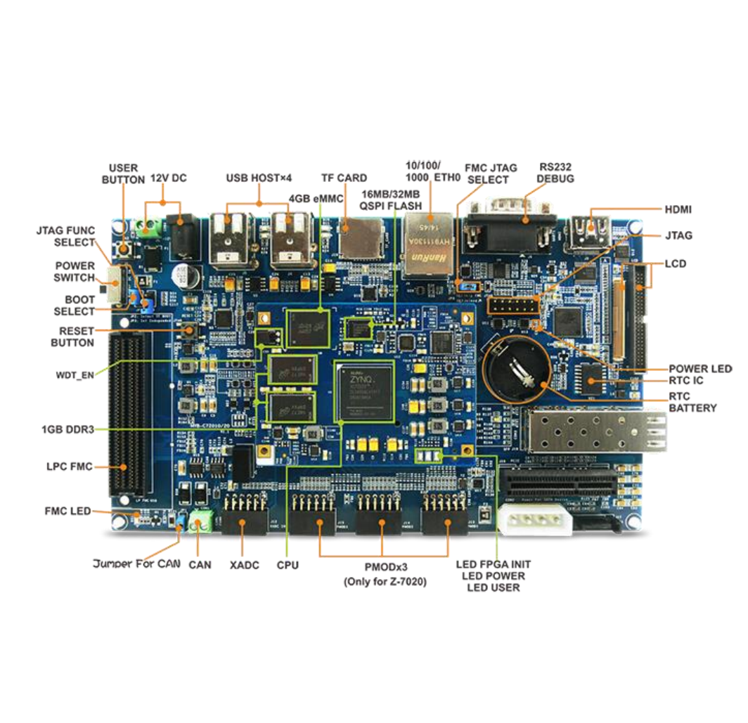
MYD-Y7Z010/007S Development Board
MYC-Y7Z010/007S CPU Module as Controller Board
1.27mm pitch 180-pin Stamp Hole Expansion Interface for Board-to-Board Connections
667MHz Xilinx XC7Z010 or XC7Z007S ARM Cortex-A9 Processor with Xilinx 7-series FPGA logic
512MB DDR3 SDRAM (2 x 256MB, 32-bit)
4GB eMMC Flash, 16MB QSPI Flash
USB Host, 3 x Gigabit Ethernet ports, RS232, RS485, CAN, TF, JTAG, GPIO…
Optional 4.3 or 7 inch LCD Module, WiFi Module, Camera Module and IO Extension Cape
Ready-to-Run Linux 3.15.0
Figure 1-1 MYD-Y7Z010/007S Development Board
Description
The MYD-Y7Z010/007S development board is powered by Xilinx XC7Z007S (Zynq-7007S) or XC7Z010 ( Zynq7010) SoC device. It is a cost-effective and high-performance solution for industrial application such as Industrial
Ethernet, machine vision, PLC/HMI and etc. The board is ready to run Linux and supports industrial operating
temperature ranging from -40 to +85 Celsius.
The MYD-Y7Z010/007S development board employs the MYC-Y7Z010/007S as the controller board by
populating the CPU Module on its base board through 1.27mm pitch 180-pin stamp-hole (Castellated-Hole)
interface, allowing users to take the advantages of numerous extended out signals. Core components on CPU
Module including Z-7010 or Z-7007S processor, 512MB DDR3 SDRAM, 4GB eMMC, 16MB QSPI Flash, Gigabit
Ethernet PHY and external watchdog. Additionally, the MYD-Y7Z010/007S development board takes full features
of the Z-7010 or Z-7007S all programmable SoC to create a rich set of peripherals to the base board through headers
and connectors including RS232, RS485, USB Host, three Gigabit Ethernet ports, CAN, TF card slot, JTAG as
well as one 2.54mm pitch 2 x 25-pin expansion header to let more GPIOs available for further extension.
1/9
�Figure 1-2 MYD-Y7Z010/007S Development Board
MYIR has designed an IO expansion board MYD-Y7Z010/007S IO Cape to connect to the MYD-Y7Z010/007S
development board via the 2.54mm pitch 2 x 25-pin expansion header to expand and enhances its functionality
with added peripherals and signals including HDMI, Camera, LCD and Pmods.
Figure 1-3 MYD-Y7Z010/007S IO Cape
Figure 1-4 IO Cape Mounted on Development Board
The 4.3- and 7-inch LCD Modules as well as MY-CAM011B camera module from MYIR can be supported through
the MYD-Y7Z010/007S IO Cape. Optional USB WiFi and Camera modules are also provided. With all these
features, the MYD-Y7Z010/007S board is not only great for integration into custom design, but also can be used
as a stand-alone development board for evaluating solutions based on Xilinx Zynq-7000.
2/9
�Hardware Specification
The Zynq®-7000 All Programmable SoC (AP SoC) family integrates the software programmability of an ARM®based processor with the hardware programmability of an FPGA, enabling key analytics and hardware acceleration
while integrating CPU, DSP, ASSP, and mixed signal functionality on a single device. Consisting of single-core Zynq7000S and dual-core Zynq-7000 devices, the Zynq-7000 family is the best price to performanceper-watt, fully
scalable SoC platform for your unique application requirements.
Zynq-7000S
Zynq-7000S devices feature a single-core ARM Cortex™-A9 processor mated with 28nm Artix®-7 based
programmable logic, representing the lowest cost entry point to the scalable Zynq-7000 platform. It includes Zynq
Z-7007S, Z-7012S and Z-7014S which target smaller embedded designs. Available with 6.25Gb/s transceivers and
outfitted with commonly used hardened peripherals, the Zynq-7000S delivers cost-optimized system integration
ideal for industrial IoT applications such as motor control and embedded vision.
Figure 1-5 Zynq Z-7000S SoC Device Block Diagram
3/9
�Zynq-7000
Zynq-7000 devices are equipped with dual-core ARM Cortex-A9 processors integrated with 28nm Artix-7 or
Kintex®-7 based programmable logic for excellent performance-per-watt and maximum design flexibility. With
up to 6.6M logic cells and offered with transceivers ranging from 6.25Gb/s to 12.5Gb/s, Zynq-7000 devices enable
highly differentiated designs for a wide range of embedded applications including multi-camera drivers
assistance systems and 4K2K Ultra-HDTV.
Figure 1-6 Zynq Z-7000 SoC Device Block Diagram
4/9
�Figure 1-7 Zynq Z-7000 and Z-7000S SoC Device Table
Mechanical Parameters
Dimensions: 153mm x 80mm (base board), 75mm x 50mm (CPU Module)
PCB Layers: 4-layer design (base board), 10-layer design (CPU Module)
Power supply: 12V/2A
Working temp.: -40~85 Celsius
The MYD-Y7Z010/007S Controller Board (MYC-Y7Z010/007S CPU Module)
Figure 1-8 MYC-Y7Z010/007S CPU Module
5/9
�SoC
Xilinx XC7Z010-1CLG400I (Zynq-7010) or XC7Z007S-1CLG400I (Zynq-7007S)
ARM® Cortex™-A9 MPCore processor
- 667MHz dual-core processor (up to 866MHz, for XC7Z010)
- 667MHz single-core processor (up to 766MHz, for XC7Z007S)
- Integrated Artix-7 class FPGA subsystem
with 28K logic cells, 17,600 LUTs, 80 DSP slices (for XC7Z010)
with 23K logic cells, 14,400 LUTs, 66DSP slices (for XC7Z007S)
- NEON™ & Single / Double Precision Floating Point for each processor
- Supports a Variety of Static and Dynamic Memory Interfaces
Memory
512MB DDR3 SDRAM
4GB eMMC Flash
16MB QSPI Flash
Peripherals and Signals Routed to Pins
MYC-Y7Z010/007S Pinouts Description
Gigabit Ethernet PHY
External watchdog
Three LEDs
- One red LED for power indicator
- One green LED for FPGA program done indicator
- One flashing green LED for system indicator
1.27mm 180-pin expansion connectors bring out below signals:
- One Gigabit Ethernet
- One USB OTG2.0 (need external USB PHY-USB3320)
- Two Serial ports
- Two I2C
- Two CAN BUS
- Two SPI
* Serial ports, I2C, CAN and SPI signals can be implemented through PL pins by Emio
- Two ADC (two independent differential ADC, 16-channel ADC brought out through PL pins)
- One SDIO
The MYD-Y7Z010/007S Base Board
PS Unit
One USB Host
One RS232 serial port (with isolation)
One RS485 (with isolation)
One TF card slot
One CAN interface (with isolation)
One 10/100/1000Mbps Ethernet interface
One 2.54mm pitch 14-pin JTAG interface
One Debug serial port (UART)
6/9
�PL Unit
One 2.54mm pitch 2 x 25-pin GPIO expansion headers
Two 10/100/1000Mbps Ethernet interfaces
Three user LEDs
Function Block Diagram
Figure 1-9 Function Block Diagram of MYD-Y7Z010/007S
Dimension Chart
Figure 1-10 Dimension Chart of MYD-Y7Z010/007S
7/9
�Software Features
Item
Features
Description
Cross
compiler
gcc 4.6.1
gcc version 4.6.1
(SourceryCodeBench Lite 2011.09-50)
BOOT.BIN
First boot program including FSBL, bitstream
Source code provided
u-boot
Secondary boot program
Source code provided
Boot
program
Linux Kernel Linux 3.15.0
USB Host
Ethernet
MMC/SD/TF
CAN
Customized kernel for MYD-Y7Z010/007S
Development Board
Source code provided
Gigabit Ethernet driver
Source code provided
USB Host driver
MMC/SD/TF card driver
CAN driver
LCD Controller LCD driver
Drivers
HDMI
HDMI (SII902X chip) driver
UART
UART driver
Button
LED
GPIO
QSPI
RTC
Button driver
LED driver
GPIO driver
QSPI Flash W25Q128FW driver
DS3231 RTC driver
Resistive Touch TSC2007 resistive touch screen driver
Capacitive
Touch
FT5X0X capacitive touch screen driver
Ramdisk
Ramdisk system image
ADC
File System
Rootfs.tar
ADC driver
Tar file
Table 1-1 Software Features of MYD-Y7Z010/007S
8/9
Remark
Source code provided
Source code provided
Source code provided
Source code provided
Source code provided
Source code provided
Source code provided
Source code provided
Source code provided
Source code provided
Source code provided
Source code provided
Source code provided
Source code provided
�Order Information
Item
Part No.
MYD-Y7Z010 Development Board
MYD-Y7Z010-4E512D-667-I
MYD-Y7Z007S Development Board
MYD-Y7Z007S-4E512D-667-I
MYC-Y7Z010 CPU Module
MYC-Y7Z010-4E512D-667-I
MY-WF003U WiFi Module
MY-WF003U
MY-CAM011B Camera Module
MY-CAM011B
MYC-Y7Z007S CPU Module
MYC-Y7Z007S-4E512D-667-I
MY-CAM002U Camera Module
MY-CAM002U
MY-LCD43TP 4.3-inch LCD Module
with resistive touch screen
MY-LCD70TP 7-inch LCD Module
with resistive touch screen
MY-LCD70TP-C 7-inch LCD Module
with capacitive touch screen
MYD-Y7Z010/007S IO CAPE
MY-TFT043RV2
MY-TFT070RV2
MY-TFT070CV2
MY-CAPE003
Packing List
One MYD-Y7Z010/007S Board
(including the base board and CPU
module)
One 1.5m cross Ethernet cable
One DB9 converting cable
One power converting cable
One 12V/1.25A Power adapter
One Product Disk
(including user manual, datasheet,
base board schematic in PDF format
and software packages)
Add-on Options:
MYC-Y7Z010/007S CPU Module
MY-LCD43TP LCD Module
MY-LCD70TP LCD Module
MY-LCD70TP-C LCD Module
MY-CAM002U Camera Module
MY-WF003U Camera Module
MY-CAM011B Camera Module
MYD-Y7Z010/007S IO CAPE
Remark: the MY-CAM011B Camera Module and LCD Modules are supported through IO CAPE.
MYIR Tech Limited
Room 04, 6th Floor, Building No.2, Fada Road, Yunli Smart Park, Bantian,
Longgang District, Shenzhen, Guangdong, China 518129
E-mail: sales@myirtech.com
Phone: +86-755-22984836
Fax: +86-755-25532724
Website: http://www.myirtech.com
9/9
�