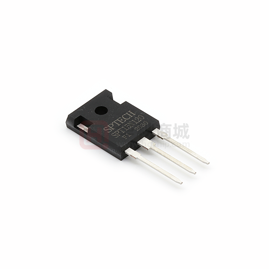
SPT15N120F1A
1200V /15A Trench Field Stop IGBT
Field Stop Trench IGBTs offer low
switching losses, high energy efficiency and
high avalanche ruggedness for soft switching
applications
such
as
inductive
heating,
VCE
1200
V
IC
15
A
VCE(SAT) IC=15A
1.9
V
microwave oven, etc.
FEATURES
Trench-Stop Technology offering :
High speed switching
High ruggedness, temperature stable
Low VCEsat
Easy parallel switching capability due
to positive temperature coefficient in
VCEsat
Soft current turn-off waveforms
Enhanced avalanche capability
APPLICATION
Inductive cooking
Inverterized microwave ovens
Resonant converters
Soft switching applications
http://www.superic-tech.com
1
2018.06 / Rev3.1
�SPT15N120F1A
Maximum Ratings
Parameter
Symbol
Value
Unit
Collector-Emitter Breakdown Voltage
VCE
1200
V
DC collector current, limited by Tjmax
TC = 25°C
TC = 100°C
IC
30
15
A
Diode Forward current, limited by Tjmax
TC = 25°C
TC = 100°C
IF
30
15
A
Pulsed collector current, tp limited by Tjmax
ICpuls
45
A
Turn off safe operating area VCE ≤1200V,
Tj ≤ 150°C
-
45
A
Operating junction temperature Tj
-
-40...+150
°C
Storage temperature
Ts
-55...+150
°C
Soldering temperature, wave soldering 1.6mm
(0.063in.) from case for 10s
-
260
°C
Thermal Resistance
Parameter
Symbol
Max. Value
IGBT thermal resistance,
junction - case
Rθ(j-c)
0.7
K/W
Diode thermal resistance,
junction - case
Rθ(j-c)
1.5
K/W
Thermal resistance,
junction - ambient
Rθ(j-a)
40
K/W
http://www.superic-tech.com
2
Unit
2018.06 / Rev3.1
�SPT15N120F1A
Electrical Characteristics of the IGBT(Tj= 25℃ unless otherwise specified):
Parameter
Symbol
Conditions
Min.
Typ.
Max.
Unit
1200
-
-
V
5.1
5.8
6.4
V
Static
Collector-Emitter
breakdown voltage
BVCES
VGE=0V , IC=250μA ①
Gate threshold voltage
VGE(th)
VGE=VCE, IC=250μA
Collector-Emitter
Saturation voltage
VCE(sat)
VGE=15V, IC=15A
Tj = 25°C
Tj = 150°C
-
1.9
2.3
2.3
-
V
Zero gate voltage
collector current
ICES
VCE = 1200V, VGE = 0V
Tj = 25°C
Tj = 150°C
-
-
100
1000
μA
-
Gate-emitter
leakage current
IGES
VCE = 0V, VGE = 20V
-
-
100
nA
Parameter
Symbol
Conditions
Min.
Typ.
Max.
Unit
Dynamic
Input capacitance
Cies
Output capacitance
Coes
Reverse transfer
capacitance
Cres
Gate charge
QG
VCE = 25V, VGE = 0V,
f = 1MHz
VCC = 600V, IC = 15A,
VGE = 15V
-
1655
-
-
72
-
-
35
-
-
101
-
pF
nC
Switching Characteristic, Inductive Load
Parameter
Symbol
Conditions
Min.
Typ.
Max.
Unit
Dynamic , at Tj = 25°C
Turn-off delay time
td(off)
Fall time
Turn-off energy
tf
Eoff
VCC = 600V, IC = 15A,
VGE = 0/15V,
Rg=12Ω
-
80
-
ns
-
200
-
ns
-
0.28
-
mJ
Note:
① BVces testing without filter could damage the device. BVces is guaranteed by Ices@1200V test.
http://www.superic-tech.com
3
2018.06 / Rev3.1
�SPT15N120F1A
Electrical Characteristics of the DIODE(Tj= 25℃ unless otherwise specified)
Parameter
Symbol
Conditions
Min.
Typ.
Max.
Unit
Dynamic
Diode Forward Voltage
VFM
Reverse Recovery Time
Trr
Reverse Recovery Current
Irr
Reverse Recovery Charge
Qrr
http://www.superic-tech.com
IF = 15A
IF= 10A,
di/dt= 200A/μs
4
-
2.3
-
V
-
70
-
ns
-
5
-
A
-
1600
-
nC
2018.06 / Rev3.1
�SPT15N120F1A
http://www.superic-tech.com
5
2018.06 / Rev3.1
�
很抱歉,暂时无法提供与“SPT15N120F1”相匹配的价格&库存,您可以联系我们找货
免费人工找货- 国内价格
- 1+7.15000
- 10+6.60000
- 30+6.49000
- 国内价格
- 1+9.68760
- 10+8.04600
- 30+6.90120
- 90+5.87520
- 510+5.42160
- 990+5.22720
