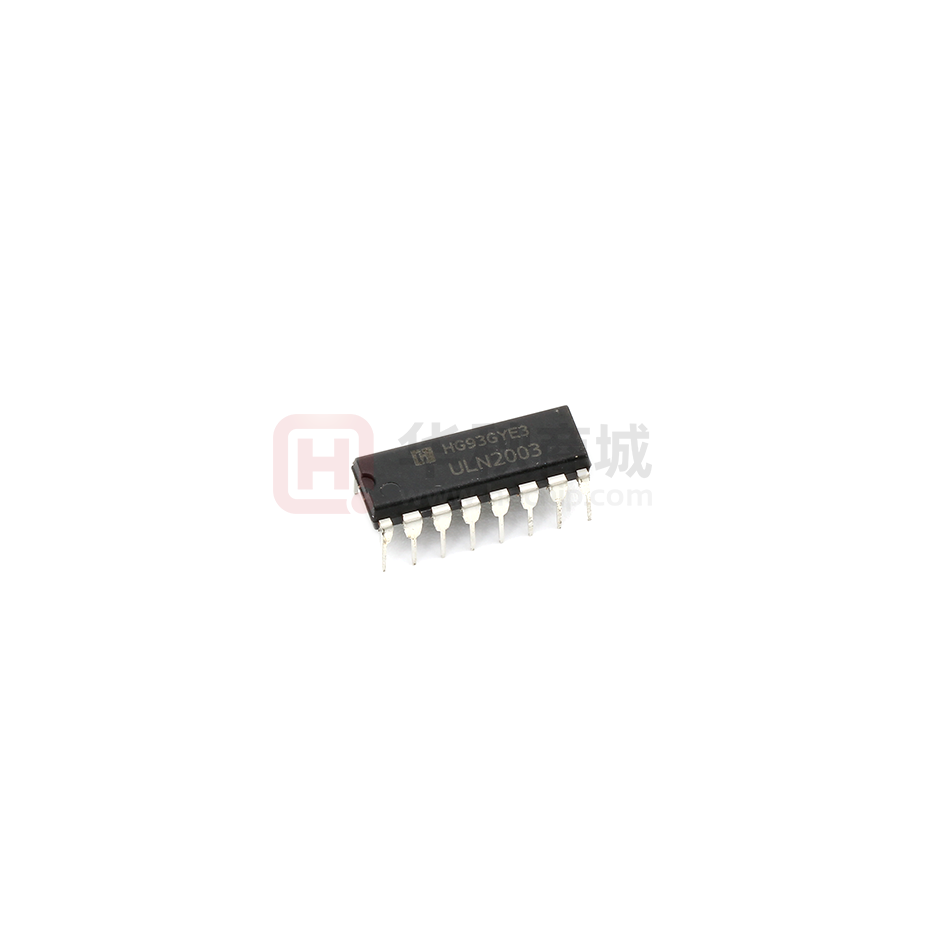
ULN2003
High Voltage, High Current
Darlington Transistor Arrays
The seven NPN Darlington connected transistors in these arrays are
well suited for driving lamps, relays, or printer hammers in a variety of
industrial and consumer applications. Their high breakdown voltage
and internal suppression diodes insure freedom from problems
associated with inductive loads. Peak inrush currents to 500 mA
permit them to drive incandescent lamps.
The ULx2003A with a 2.7 kW series input resistor is well suited for
systems utilizing a 5.0 V TTL or CMOS Logic.
16
1
SOIC-16
D SUFFIX
CASE 751B
Features
•�These are Pb-Free Devices
1/7 ULx2003A
2.7 k
Pin 9
1
16
2
15
3
14
4
13
5
12
6
11
7
10
8
9
5.0 k
3.0 k
Figure 1. Representative Schematic Diagram
(Top View)
Figure 2. Pin Connections
http://www.hgsemi.com.cn
1
2016 APR
�ULN2003
MAXIMUM RATINGS (TA = 25°C, and rating apply to any one device in the package, unless otherwise noted.)
Rating
Symbol
Value
Unit
Output Voltage
VO
50
V
Input Voltage
VI
30
V
Collector Current - Continuous
IC
500
mA
Base Current - Continuous
IB
25
mA
Operating Ambient Temperature Range
ULN2003A
ULQ2003A
TA
Storage Temperature Range
Tstg
-55 to +150
°C
Junction Temperature
TJ
150
°C
°C
-20 to +85
-40 to +85
Thermal Resistance, Junction-to-Ambient
Case 751B, D Suffix
RqJA
Thermal Resistance, Junction-to-Case
Case 751B, D Suffix
RqJC
Electrostatic Discharge Sensitivity (ESD)
Human Body Model (HBM)
Machine Model (MM)
Charged Device Model (CDM)
ESD
°C/W
100
°C/W
20
V
2000
400
1500
Stresses exceeding Maximum Ratings may damage the device. Maximum Ratings are stress ratings only. Functional operation above the
Recommended Operating Conditions is not implied. Extended exposure to stresses above the Recommended Operating Conditions may affect
device reliability.
http://www.hgsemi.com.cn
1
2016 APR
�ULN2003
ELECTRICAL CHARACTERISTICS (TA = 25°C, unless otherwise noted)
Symbol
Characteristic
Output Leakage Current
(VO = 50 V, TA = +85°C)
(VO = 50 V, TA = +25°C)
Min
Typ
Max
-
-
100
50
-
1.1
0.95
0.85
1.6
1.3
1.1
-
0.93
1.35
-
-
2.4
2.7
3.0
Unit
mA
ICEX
Collector-Emitter Saturation Voltage
(IC = 350 mA, IB = 500 mA)
(IC = 200 mA, IB = 350 mA)
(IC = 100 mA, IB = 250 mA)
VCE(sat)
V
Input Current - On Condition
(VI = 3.85 V)
II(on)
Input Voltage - On Condition
(VCE = 2.0 V, IC = 200 mA)
(VCE = 2.0 V, IC = 250 mA)
(VCE = 2.0 V, IC = 300 mA)
VI(on)
Input Current - Off Condition
(IC = 500 mA, TA = 85°C)
II(off)
50
100
-
mA
DC Current Gain
(VCE = 2.0 V, IC = 350 mA)
hFE
1000
-
-
-
Input Capacitance
CI
-
15
30
pF
Turn-On Delay Time
(50% EI to 50% EO)
ton
-
0.25
1.0
ms
Turn-Off Delay Time
(50% EI to 50% EO)
toff
-
0.25
1.0
ms
IR
-
-
50
100
mA
VF
-
1.5
2.0
V
Clamp Diode Leakage Current
(VR = 50 V)
TA = +25°C
TA = +85°C
Clamp Diode Forward Voltage
(IF = 350 mA)
http://www.hgsemi.com.cn
1
mA
V
2016 APR
�ULN2003
TYPICAL PERFORMANCE CURVES - TA = 25°C
400
I O , OUTPUT CURRENT (mA)
I O , OUTPUT CURRENT (mA)
400
300
200
100
0
0
1.0
2.0
3.0
4.0
5.0
8.0
9.0
10
11
200
100
0
12
50
0
100
150
200
250
300
350
VI, INPUT VOLTAGE (V)
II, INPUT CURRENT (mA)
Figure 3. Output Current versus Input Voltage
Figure 4. Output Current versus Input Current
800
400
2.5
700
PIN 13
600
I I, INPUT CURRENT (mA)
IC , COLLECTOR CURRENT (mA)
300
PIN 10
1 Output Conducting at a Time
500
PIN 16
400
300
200
2.0
Maximum
1.5
Typical
1.0
0.5
100
0
0
0
0.2
0.4
0.6
0.8
1.0
1.2
1.4
0
1.6
1.0
2.0
3.0
4.0
5.0
6.0
VCE(sat), SATURATION VOLTAGE (V)
VI, INPUT VOLTAGE (V)
Figure 5. Typical Output Characteristics
Figure 6. Input Characteristics
7.0
1
700
2
500
3
300
4
5
200
6
7
100
10
20
30
50
70
NUMBER OF DRIVERS USED
I C, COLLECTOR CURRENT (mA)
1000
100
% DUTY CYCLE
Figure 7. Maximum Collector Current
versus Duty Cycle
(and Number of Drivers in Use)
http://www.hgsemi.com.cn
1
2016 APR
8.0
�
很抱歉,暂时无法提供与“ULN2003N”相匹配的价格&库存,您可以联系我们找货
免费人工找货- 国内价格
- 5+0.56000
- 20+0.55000
- 100+0.53000
