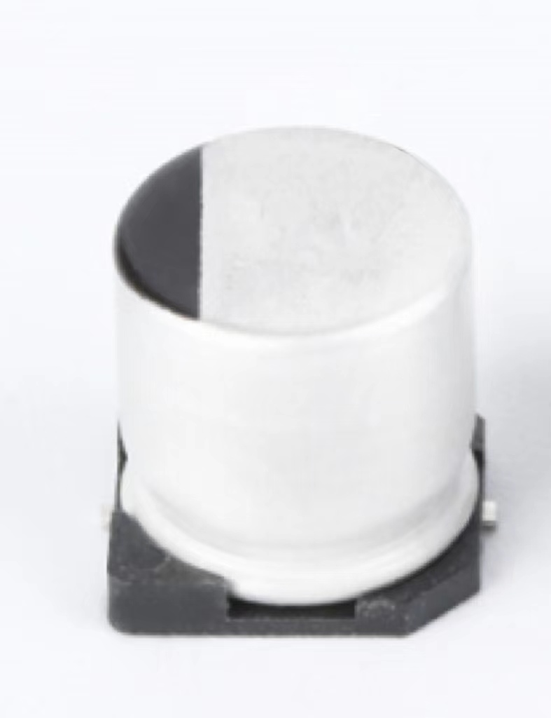
SURFACE MOUNT ALUMINUM ELECTROLYTIC CAPACITORS
MVG(MV)-BP Series
•85℃ 2,000Hrs assured.
•Vertical SMD type.
•Bi-polarized.
•For LED MT / TV.
•RoHS compliant.
•Halogen-free capacitors are also available.
BDS(MVK)-BP Series
Solventproof
•105℃ 1,000Hrs assured.
MVG(MV)
-BP
MV
•Vertical SMD type.
•Bi-polarized.
•Wide Temperature Range.
•For LED MT / TV.
•RoHS compliant.
•Halogen-free capacitors are also available.
BDS(MVK)
-BP
Wide Temp.
Bi-polarized
SPECIFICATIONS
Item
Characteristics
Series Name
Rated Voltage Range
Operating Temperature Range
Capacitance Tolerance
Leakage Current
(In both directions)
MVG(MV)-BP
4 ~ 50 V DC
-40 ~ +85℃
BDS(MVK)-BP
6.3 ~ 50 V DC
-40 ~ +105℃
±20%(M)
(at 20℃, 120Hz)
I=0.05CV(μA) or 10μA, whichever is greater.
Where, I:Max. Leakage current(μA), C:Nominal capacitance(μF), V:Rated voltage(VDC) (at 20℃, after 2 minutes)
Rated Voltage(VDC)
4
6.3
10
16
25
35~50
MV-BP
0.45
0.32
0.26
0.24
0.22
0.20
MVK-BP
-
0.35
0.26
0.24
0.20
0.18
Dissipation Factor(Tan δ
)
(at 20℃, 120Hz)
Rated Voltage(VDC)
Z (-25℃)/Z(20℃)
Z (-40℃)/Z(20℃)
Temperature Characteristics
(Max. Impedance ratio)
4
7
15
6.3
4
10
10
3
8
16
2
6
25
2
4
35~50
2
3
The following specifications shall be satisfied when the capacitors are restored to 20℃ after the rated
voltage is applied with the following conditions with its polarization reversed every 250 hours.
Series Name
Test time & temperature
Capacitance change
Tanδ
Leakage current
Load Life
MVG(MV)-BP
2,000 hours at 85℃
≦±20% of the initial value
≦200% of the initial specified value
≦The initial specified value
BDS(MVK)-BP
1,000 hours at 105℃
≦±30% of the initial value
≦300% of the initial specified value
≦The initial specified value
The following specifications shall be satisfied when the capacitors are restored to 20℃ after exposing
MVG(MV)-BP) or 105℃(B
BDS(MVK)-BP) without voltage applied. The rated
them for 500 hours at 85℃(M
voltage shall be applied to the capacitors for a minimum of 30 minutes, at least 24 hours and not more
than 48 hours before the measurements.
Shelf Life
Series Name
Capacitance change
Tanδ
Leakage current
Others
MVG(MV)-BP
≦±15% of the initial value
≦150% of the initial specified value
≦The initial specified value
BDS(MVK)-BP
≦±25% of the initial value
≦200% of the initial specified value
≦The initial specified value
Satisfied characteristics KS C IEC 60384-4
PART NUMBERING SYSTEM
MVG 16
VC
22
M
BP F55 TP
With tape
Case code
Bi-polar type
Capacitance tolerance(±20%)
Nominal capacitance code
(ex. 1.0㎌:1, 4.7㎌:4R7, 10㎌:10)
Lead type
Rated voltage
Series name
83
MVG(MV)-BP/
BDS (MVK)-BP Series
(at 120Hz)
�SURFACE MOUNT ALUMINUM ELECTROLYTIC CAPACITORS
DIMENSIONS OF MVG(MV)-BP, BDS(MVK)-BP Series
DIMENSIONS
Unit(mm)
MARKING
Recommended solder land on PC board
Note 1 : 6.3WV is marked by 6V.
Case code
D55
E55
F55
F60
ØD
4
5
6.3
6.3
L
5.2
5.2
5.2
5.7
A
4.3
5.3
6.6
6.6
B
4.3
5.3
6.6
6.6
C
5.1
5.9
7.2
7.2
W
0.5~0.8
0.5~0.8
0.5~0.8
0.5~0.8
P
1.0
1.4
1.9
1.9
a
1.0
1.4
1.9
1.9
b
2.6
3.0
3.5
3.5
c
1.6
1.6
1.6
1.6
: Solder land on PC board
RATINGS OF MVG(MV)-BP, BDS(MVK)-BP Se r i es
MVG(MV)-BP
VDC
㎌
1.0
(1.5)
2.2
3.3
4.7
(6.8)
10
(15)
22
33
47
4
6.3
10
16
D55
D55
D55
D55
12
E55
21
13
14
E55
23
F55
36
F55
25
35
D55
9
E55
15
F55
24
11
E55
18
F55
28
50
D55
8
E55
F55
F55
13
17
21
D55
D55
E55
E55
F55
5.5
6.5
9
11
14
33
Rated Ripple Current(mArms/ 85℃, 120Hz)
Case code
BDS(MVK)-BP
V DC
㎌
1.0
(1.5)
2.2
3.3
4.7
(6.8)
10
(15)
22
33
47
6.3
10
16
D55
D55
E55
F60
D55
11
E55
20
F60
35
12
E55
23
F60
25
35
D55
8
E55
16
F60
28
10
18
50
D55
7
E55
14
F60
23
D55
D55
E55
E55
F60
F60
5.3
7.2
9.0
12
16
20
32
39
Rated Ripple Current (mA rms/105℃, 120Hz)
Case code
Note : → Use next higher voltage part.
Parenthesized capacitance is not standard part.
84
�
MVG50VC47M8*6_8.0TP 价格&库存
很抱歉,暂时无法提供与“MVG50VC47M8*6_8.0TP”相匹配的价格&库存,您可以联系我们找货
免费人工找货