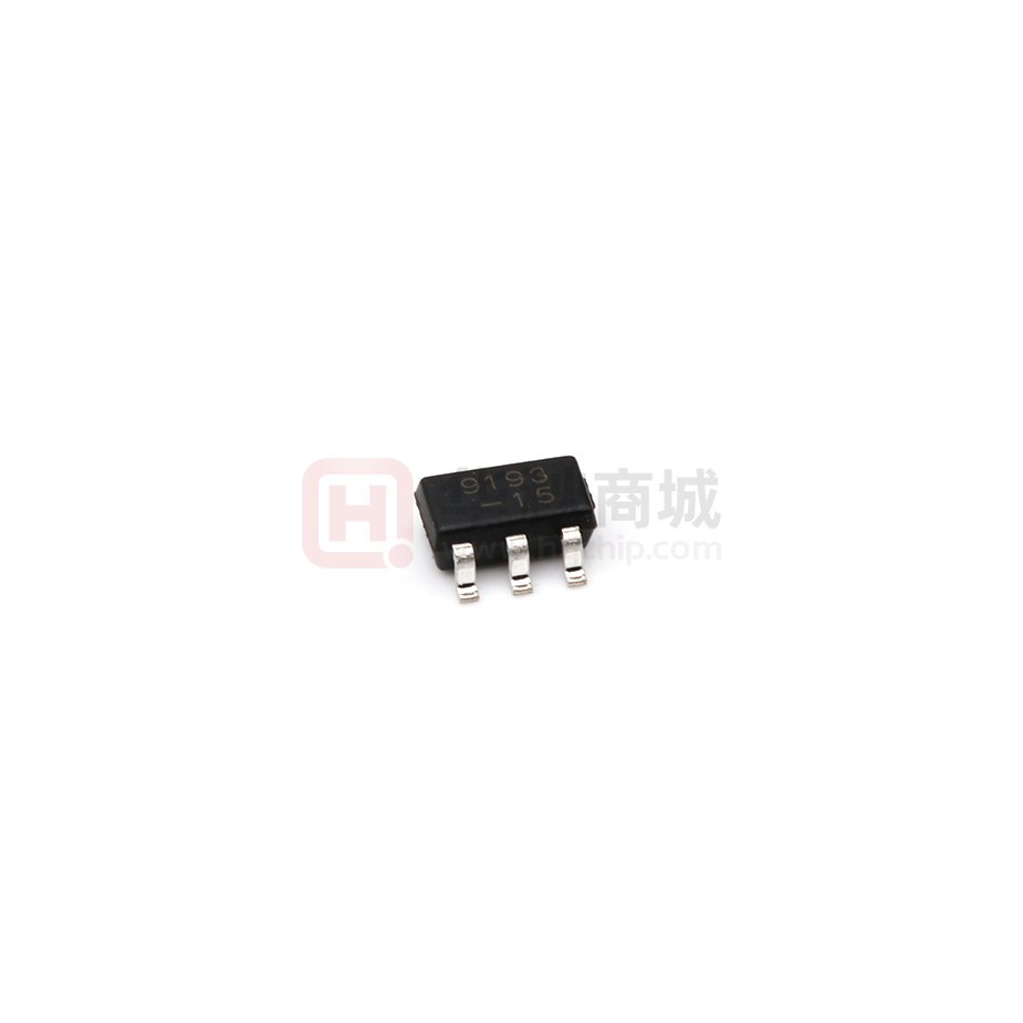
PJ9193
Low Dropout Regulators
Description
SOT-23-5
The PJ9193 is designed for portable RF and wireless
4. NC
5. VOUT
applications with demanding performance and space
requirements. The PJ9193 performance is optimized for batterypowered systems to deliver ultra low noise and low quiescent
current. Regulator ground current increases only slightly in
dropout, further prolonging the battery life. The PJ9193 also
1.VIN
2.GND
3.EN
works with low-ESR ceramic capacitors, reducing the amount of
board space necessary for power applications, critical in handheld wireless devices. The PJ9193 consumes less than 0.01μA
in shutdown mode and has fast turn-on time less than 50μs.
The other features include ultra low dropout voltage, high output
accuracy, current limiting protection, and high ripple rejection
ratio.
Features
Ultra Low Noise for RF Application
Ultra Fast Response in Line/Load Transient
Maximum Output Current: 500mA
Low Dropout : 200mV @ 200mA
Wide Operating Voltage Ranges : 2V to 7V
Low Temperature Coefficient
Current Limiting Protection
Thermal Shutdown Protection
Function Block Diagram
Applications
Battery-Powered Equipment
CDMA/GSM Cellular Handsets
Portable Information Appliances
www.pingjingsemi.com
Revision:2.1 Apr-2020
1/7
�PJ9193
Low Dropout Regulators
Typical Application Circuit
PJ9193
VIN
CIN
1µF
Chip Enable
VIN
VOUT
GND
EN
COUT
1µF
VOUT
NC
Ordering Information
PJ9193-
Package Type
SE : SOT-23-5
Output Voltage
12 : 1.2V 15 : 1.5V 18 : 1.8V
25 : 2.5V 28 : 2.8V 30 : 3.0V
33 : 3.3V AD : Adjustable
Output current tap
M : 500mA
Functional Pin Description
Pin Name
Pin Function
EN
Chip Enable (Active High). Note that this pin is high impedance
NC
NO Connected
GND
Ground.
VOUT
Output Voltage.
VIN
Power Input Voltage.
www.pingjingsemi.com
Revision:2.1 Apr-2020
2/7
�PJ9193
Low Dropout Regulators
Absolute Maximum Ratings Note1
Ratings at 25℃ ambient temperature unless otherwise specified.
Parameter
Value
Unit
Supply Voltage
-0.3 ~ +6
V
Output Voltage
-0.3 ~ (VIN+0.3)
V
Output Current
600
mA
Power Dissipation
400
mW
Thermal Resistance,Junction-to-Ambient
250
℃/W
Thermal Resistance,Junction-to-Case
60
℃/W
-40 ~ +125
℃
-55 ~ 150
℃
Junction temperature
Storage temperature range
Note:
1. Stresses beyond those listed under absolute maximum ratings may cause permanent damage to the device. These are stress
ratings only, and functional operation of the device at these or any other conditions beyond those indicated under recommended
operating conditions is not implied. Exposure to absolute-maximum-rated conditions for extended periods my affect device reliability.
www.pingjingsemi.com
Revision:2.1 Apr-2020
3/7
�PJ9193
Low Dropout Regulators
Electrical Characteristics
(VIN=VOUT+1, EN=VIN, CIN=COUT=1µF, TA=25℃ , unless otherwise noted.)
Parameter
Symbol
Input Voltage
VIN
Output Voltage Accuracy
∆VOUT
IOUT=1mA
Quiescent Current
IQ
VIN>VOUT,EN=VIN
IOUT=0mA
Dropout Voltage
VDROP
Conditions
MIN.
TYP.
MAX.
Unit
2
6
V
-1.5
+1.5
%
90
130
µA
IOUT=200mA
130
180
IOUT=300mA
210
300
mV
Line Regulation
∆VLINE
VIN=3.6V to 5.5V
IOUT=1mA
0.17
%/V
Load Regulation
∆VLOAD
1mA1mΩ on the PJ9193 output
ensures stability. The PJ9193 still works well with
output capacitor of other types due to the wide stable
ESR range. Figure 1 shows the curves of allowable
ESR range as a function of load current for various
output capacitor values. Output capacitor of larger
capacitance can reduce noise and improve load
transient response, stability, and PSRR. The output
capacitor should be located not more than 0.5 inch from
the VOUT pin of the PJ9193 and returned to a clean
The PJ9193 features an LDO regulator enable/disable
function. To assure the LDO regulator will switch on, the
EN turn on control level must be greater than 1.2 volts.
The LDO regulator will go into the shutdown mode when
the voltage on the EN pin falls below 0.4 volts. For to
protecting the system, the PJ9193 have a quick-discharge
function. If the enable function is not needed in a specific
application, it may be tied to VIN to keep the LDO regulator
in a continuously on state.
Thermal Considerations
Thermal protection limits power dissipation in PJ9193.
When the operation junction temperature exceeds 165°C,
the OTP circuit starts the thermal shutdown function turn
the pass element off. The pass element turn on again
after the junction temperature cools by 30°C.
For continue operation, do not exceed absolute maximum
operation junction temperature 125°C. The power
dissipation definition in device is :
PD = (VIN − VOUT) x IOUT + VIN x IQ
The maximum power dissipation depends on the thermal
resistance of IC package, PCB layout, the rate of
surroundings airflow and temperature difference between
junction to ambient. The maximum power dissipation can
be calculated by following formula :
PD(MAX) = ( TJ(MAX) − TA ) /RθJA
analog ground.
Figure 1Region of Stable COUT ESR vs. Load Current
100
Instable
Where T J(MAX) is the maximum operation junction
temperature 125°C, TA is the ambient temperature and
the RθJA is the junction to ambient thermal resistance.
For recommended operating conditions specification of
PJ9193, where T J(MAX) is the maximum junction
temperature of the die (125°C) and TA is the maximum
10
COUT ESR(Ω)
Enable Function
1
ambient temperature. The junction to ambient thermal
resistance (RθJA is layout dependent) for SOT-23-5
Stable
0.1
package is 250°C/W, The maximum power dissipation
at TA = 25°C can be calculated by following formula :
0.01
PJ9193-15xU5
CIN = COUT = 1μF, X7R
PD(MAX) = (125°C − 25°C) / 250 = 400mW
0.001
0
50
100
150
200
250
300
Load Current (mA)
www.pingjingsemi.com
Revision:2.1 Apr-2020
6/7
�PJ9193
Low Dropout Regulators
Package Outline
SOT-23-5
Dimensions in mm
2.92
±0.05
0.15 ±0.02
1.9
1.6
2.8
±0.1
±0.05
10
12
R0.15MAX
0.95
0.35
R0.15MAX
0.06
12
± 0.05
0.65
± 0.03
1.1
±0.05
10
Ordering Information
Device
Package
Shipping
PJ9193
SOT-23-5
3,000/ Tape & Reel (7 inches)
www.pingjingsemi.com
Revision:2.1 Apr-2020
7/7
�
很抱歉,暂时无法提供与“PJ9193M15SE”相匹配的价格&库存,您可以联系我们找货
免费人工找货