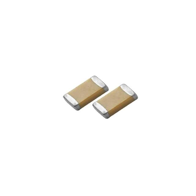
HQ Series
Multilayer Ceramic Capacitors
(High Q)
Feature
Surface mount device with high reliability
Hi-Q and low ESR at high frequencies
Low capacitance with tight tolerance
Excellent temperature characteristics
Part Numbering System
HQ
0603
CG 4R7 B
500
Meritek Series
Chip Size: 0402 / 0603 / 0805
Dielectric: CG=C0G (NPO)
Capacitance
Capacitance expressed in Pico farads (pF).
First two digits are significant figures.
Third digit denotes number of zeros.
'R' denotes decimal point for values less than 10 pF
ie. 4R7=4.2pF, 101=100pF
Tolerance
Code
Value
B
±0.1pF
C
±0.25pF
D
±0.5pF
F
±1%
F
±2%
J
±5%
Rated Voltage
Code
Value
160
16VDC
250
25VDC
500
101
201
251
501
631
50VDC 100VDC 200VDC 250VDC 500VDC 630VDC
Dimensions
Size
Inch (mm)
0402
(1005)
0603
(1608)
0805
(2012)
L (mm)
W (mm)
1.00±0.05
0.50±0.05
0.50±0.05
N
1.60±0.10
0.80±0.10
0.80±0.07
S
1.60 +0.15/-0.10
0.80 +0.15/-0.10
0.80 +0.15/-0.10
X
0.60±0.10
A
0.80±0.10
B
1.25±0.10
D
2.00±0.15
T (mm)/Symbol
1.25±0.10
MB (mm)
0.25
-0.5
0.40±0.15
0.50±0.20
L
T
W
MB
MB
Fig. 1 The outline of MLCC
Constructions
No.
Name
NP0
Ceramic material
BaTiO3 based
Inner electrode
AgPd alloy
Inner layer
Termination
Ag or Cu
Middle layer
Ni
Outer layer
Sn (Matt)
Fig. 11 The construction of MLCC
Rev. 7a
�
HQ Series
Multilayer Ceramic Capacitors
(High Q)
Capacitance Range
Capacitance
DIELECTRIC
SIZE
0.5pF (0R5)
0.6pF (0R6)
0.7pF (0R7)
0.8pF (0R8)
0.9pF (0R9)
1.0pF (1R0)
1.2pF (1R2)
1.5pF (1R5)
1.8pF (1R8)
2.2pF (2R2)
2.7pF (2R7)
3.3pF (3R3)
3.9pF (3R9)
4.7pF (4R7)
5.6pF (5R6)
6.8pF (6R8)
8.2pF (8R2)
10pF (100)
12pF (120)
15pF (150)
18pF (180)
22pF (220)
27pF (270)
33pF (330)
39pF (390)
47pF (470)
56pF (560)
68pF (680)
82pF (820)
100pF (101)
120pF (121)
150pF (151)
180pF (181)
220pF (221)
270pF (271)
330pF (331)
390pF (391)
470pF (471)
560pF (561)
680pF (681)
820pF (821)
1,000pF (102)
1,200pF (122)
1,500pF (152)
1,800pF (182)
2,200pF (222)
2,700pF (272)
3,300pF (332)
NP0
16
N^
N^
N^
N^
N^
N^
N^
N^
N^
N^
N^
N^
N^
N^
N^
N^
N^
N
N
N
N
N
N
N
N
N
N
N
N
N
N
N
N
N
N
N
N
N
0402
25
N^
N^
N^
N^
N^
N^
N^
N^
N^
N^
N^
N^
N^
N^
N^
N^
N^
N
N
N
N
N
N
N
N
N
N
N
N
N
N
N
N
N
N
N
N
N
0603
50
N^
N^
N^
N^
N^
N^
N^
N^
N^
N^
N^
N^
N^
N^
N^
N^
N^
N
N
N
N
N
N
N
N
N
N
N
N
N
N
N
N
N
N
N
N
N
16
S^
S^
S^
S^
S^
S^
S^
S^
S^
S^
S^
S^
S^
S^
S^
S^
S^
S
S
S
S
S
S
S
S
S
S
S
S
S
S
S
S
S
S
S
S
S
S
S
S
S
X
X
X
X
X
X
25
S^
S^
S^
S^
S^
S^
S^
S^
S^
S^
S^
S^
S^
S^
S^
S^
S^
S
S
S
S
S
S
S
S
S
S
S
S
S
S
S
S
S
S
S
S
S
S
S
S
S
X
X
X
X
X
X
50
S^
S^
S^
S^
S^
S^
S^
S^
S^
S^
S^
S^
S^
S^
S^
S^
S^
S
S
S
S
S
S
S
S
S
S
S
S
S
S
S
S
S
S
S
S
S
S
S
S
S
X
X
X
X
X
X
1.
0402, Capacitance 1000pF, 1.0±0.2Vrms, 1KHz±10%
* NP0: Cap≥30pF, Q≥1000; Cap0603)
Termination
* Test time: 10±1 sec.
Vibration
* Vibration frequency: 10~55 Hz/min.
* No remarkable damage.
Resistance
* Total amplitude: 1.5mm
* Cap change and Q/D.F.: To meet initial spec.
* Test time: 6 hrs. (Two hours each in three mutually
perpendicular directions.)
9.
Solderability
* Solder temperature: 235±5°C
95% min. coverage of all metalized area.
* Dipping time: 2±0.5 sec.
10. Bending Test
* The middle part of substrate shall be pressurized by
* No remarkable damage.
means of the pressurizing rod at a rate of about 1 mm per
* Cap change: within ±5.0% or ±0.5pF whichever is larger.
second until the deflection becomes 1 mm and then the
(This capacitance change means the change of capacitance
pressure shall be maintained for 5±1 sec.
under specified flexure of substrate from the capacitance
* Measurement to be made after keeping at room temp for
measured before the test.)
24±2 hrs.
11. Resistance to * Solder temperature: 270±5°C
* No remarkable damage.
Soldering
* Dipping time: 10±1 sec
Heat
* Preheating: 120 to 150°C for 1 minute before immerse the * Q/D.F., I.R. and dielectric strength: To meet initial requirements.
* Cap change: within ±2.5% or ±0.25pF whichever is larger.
capacitor in a eutectic solder.
* 25% max leaching on each edge.
* Measurement to be made after keeping at room temp for
24±2 hrs. (Class I) or 48±4 hrs. (Class II).
12. Temperature
Cycle
* Conduct the five cycles according to the temperatures and * No remarkable damage.
time.
Step
1
2
3
4
* Cap change:within ±2.5% or ±0.25pF whichever is larger.
Temp. (°C)
Min. operating temp. +0/-3
Room temp.
Max operating temp. +3/-0
Room temp.
Time (min.)
30±3
2~3
30±3
2~3
* Q/D.F., I.R. and dielectric strength: To meet initial requirements.
* Measurement to be made after keeping at room temp for
24±2 hrs.
* Test temp.: 40±2°C
* No remarkable damage.
(Damp Heat)
* Humidity: 90~95% RH
* Cap change: within ±5.0% or ±0.5pF whichever is larger.
Steady State
* Test time: 500+24/-0hrs.
* Q/D.F. value:
13. Humidity
* Measurement to be made after keeping at room temp for
24±2 hrs.
NP0: Cap≥30pF, Q≥350; 10pF≤Cap
很抱歉,暂时无法提供与“HQ0402CG100G500”相匹配的价格&库存,您可以联系我们找货
免费人工找货