Product specification – May 25, 2004 V.1 Supersedes Date of Nov. 11, 2003
DATA SHEET
CHIP RESISTORS
RT Series (Pb Free)
1%; 0.5%; 0.25%; 0.1%
�2
Chip Resistor Surface Mount
RT
9
(Pb Free)
SERIES
SCOPE
This specification describes RT series chip resistors with lead-free terminations made by thin film process.
ORDERING INFORMATION
Part number is identified by the series, size, tolerance, packing style, temperature coefficient, special type and
resistance value.
RT XXXX X X X XX XXXX L
(1)
(2) (3) (4) (5)
(6)
(7)
MARKING
RT0805/RT1206/RT1210/RT2010/RT2512
(1) SIZE
0201 = 0.024×0.012
0402 = 0.040×0.020
0603 = 0.063×0.033
0805 = 0.083×0.051
1206 = 0.122×0.063
1210 = 0.122×0.102
2010 = 0.197×0.098
2512 = 0.250×0.126
Either resistance in E-24 or E-96: 4 digits
First three digits for significant figure and 4th
digit for number of zeros
ynsc004
Fig. 1 Value=10KΩ
RT0603
E-24 series: 3 digits
First two digits for significant figure and 3rd
digit for number of zeros
ynsc015
Fig. 2 Value=12KΩ
(2) TOLERANCE
L = ±0.01% (on request)
W = ±0.05% (on request)
B= ±0.1%
C= ±0.25%
D= ±0.5%
F = ±1%
(3) PACKAGING TYPE
R = Paper taping reel
K = Embossed Plastic Tape Reel
(4) TEMPERATURE
CHARACTERISTIC OF
RESISTANCE
B = ±10 ppm/°C (on request)
C = ±15 ppm/°C (on request)
D = ±25 ppm/°C
E = ±50 ppm/°C
(5) SPECIAL TYPE
07 = 7 inch dia. Reel
13 = 13 inch dia. Reel
(6) RESISTANCE VALUE
5R6, 56R, 560R, 5K6, 56K, 1M
(7) RESISTOR TERMINATIONS
L = Lead free terminations (pure Tin)
E-96 series: 3 digits for 0603±1% EIA-96
marking method. See Table 1
��+
ynsc002
Fig. 3 Value=12.4KΩ
RT0201/ RT0402/ RESISTANCE VALUE IS NOT IN E-24 / E96 SERIES
No value marking
ynsc007
Fig. 4
EIA - 96 MARKING RULE
Table 1 shows the first two digits of the three-digit EIA-96 part-marking scheme.
Code Value Code Value Code Value Code Value Code Value Code Value Code Value Code Value
01
02
03
04
05
06
07
08
09
10
11
12
100
102
105
107
110
113
115
118
121
124
127
130
13
14
15
16
17
18
19
20
21
22
23
24
133
137
140
143
147
150
154
158
162
165
169
174
25
26
27
28
29
30
31
32
33
34
35
36
178
182
187
191
196
200
205
210
215
221
226
232
37
38
39
40
41
42
43
44
45
46
47
48
237
243
249
255
261
267
274
280
287
294
301
309
49
50
51
52
53
54
55
56
57
58
59
60
316
324
332
340
348
357
365
374
383
392
402
412
61
62
63
64
55
66
67
68
69
70
71
72
422
432
442
453
464
475
487
499
511
523
536
549
73
74
75
76
77
78
79
80
81
82
83
84
562
576
590
604
619
634
649
665
681
698
715
732
85
86
87
88
89
90
91
92
93
94
95
96
750
768
787
806
825
845
866
887
909
931
953
976
The third character is a letter multiplier:
X=10 -1 , Y=10 -2 , A=10 0, B=10 1, C=10 2, D=10 3, E=10 4, F=10 5
www.yageo.com
May 25, 2004 V.1
�3
Chip Resistor Surface Mount
RT
SERIES
9
(Pb Free)
CONSTRUCTION
The resistors are constructed out of
protective coat
a high-grade ceramic body. Internal
handbook, 4 columns
resistive layer
metal electrodes are added at each
end and connected by a resistive
inner electrode
H
material. The composition of the
end termination
resistive material is adjusted to give
ceramic substrate MBE940_d
I2
the approximate required resistance
and laser cutting of this resistive
Fig. 5 Chip resistor construction
layer that achieves tolerance trims
the value. The resistive layer is
covered with a protective coat and printed with the resistance value. Finally, the two external terminations (pure Tin) are
added. See fig.5
DIMENSION
Table 2
For dimension see Table 2
protective coat
I1
TYPE
L (mm) W (mm)
H (mm)
I1 (mm)
I2 (mm)
RT0201
0.6±0.10 0.30±0.05 0.25±0.05 0.15±0.10 0.15±0.10
RT0402 1.00±0.10 0.50±0.05 0.35±0.05 0.20±0.10 0.25±0.10
RT0603 1.60±0.10 0.80±0.10 0.45±0.10 0.25±0.15 0.25±0.15
W
RT0805 2.00±0.10 1.25±0.10 0.50±0.10 0.35±0.20 0.35±0.20
RT1206 3.10±0.10 1.60±0.10 0.55±0.10 0.45±0.20 0.40±0.20
MBE940_a
RT1210 3.10±0.10 2.60±0.15 0.55±0.10 0.50±0.20 0.50±0.20
L
RT2010 5.00±0.10 2.50±0.15 0.55±0.10 0.60±0.20 0.50±0.20
Fig. 6 Chip resistor dimension
RT2512 6.35±0.10 3.20±0.15 0.55±0.10 0.60±0.20 0.50±0.20
POWER RATING
RATED POWER AT 70°C:
RATED VOLTAGE:
Pmax halfpage
handbook,
(%Prated )
100
MLB206_a
The DC or AC (rms) continuous working voltage
corresponding to the rated power is determined by
the following formula:
V=√(P X R)
50
Where
0
−55
0
50
70 85 100
125
Precision Standard
155
Tamb (°C)
Powr
Fig. 7 Maximum dissipation (Pmax) in percentage of rated
power as a function of the operating ambient
temperature (Tamb)
V=Continuous rated DC
or AC (rms) working voltage (V)
P=Rated power (W)
R=Resistance value (X)
www.yageo.com
May 25, 2004 V.1
�4
Chip Resistor Surface Mount
RT
9
(Pb Free)
SERIES
ELECTRICAL CHARACTERISTICS
Table 3
CHARACTERISTICS
RT0201
OPERATION MODE
Precision Standard Power
POWER RATING @ 70°C
OPERATING
TEMPERATURE RANGE
RESISTANCE RANGE
IN E-24/E-96
(E-192; special value on
Request)
1/64W 1/20W 1/16W
RT0402
RT0603
RT0805
Precision Standard Power Precision Standard Power
Precision Standard Power
1/64W 1/16W 1/10W
1/32W 1/10W 1/8W
1/20W
1/8W
1/5W
–10°C to +85°C for precision type; –55°C to +125°C for standard; –55°C to +155°C for power type
33Ω~22KΩ
(
很抱歉,暂时无法提供与“RT0805WRB07110KL”相匹配的价格&库存,您可以联系我们找货
免费人工找货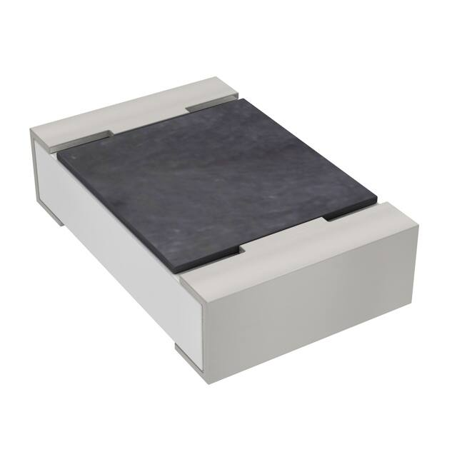


 工商网监
湘ICP备2023018690号
工商网监
湘ICP备2023018690号
