物料型号:文档描述的是国巨(YAGEO)的RT系列贴片电阻,这些电阻采用无铅端子,由薄膜工艺制成。
器件简介:RT系列贴片电阻具有多种尺寸和精度,包括1%、0.5%、0.25%和0.1%的容差。电阻值可以是E-24或E-96系列,部分尺寸如RT0603、RT0805等,还有特殊的尺寸如RT0201和RT0402。
引脚分配:文档中没有明确提到引脚分配,因为这是关于电阻器的文档,电阻器通常被视为两个端点的组件。
参数特性:电阻器的参数包括尺寸、公差、包装类型、温度系数和特殊类型。电阻值的表示方法根据E-24或E-96系列有所不同,还提供了无铅端子的选项。
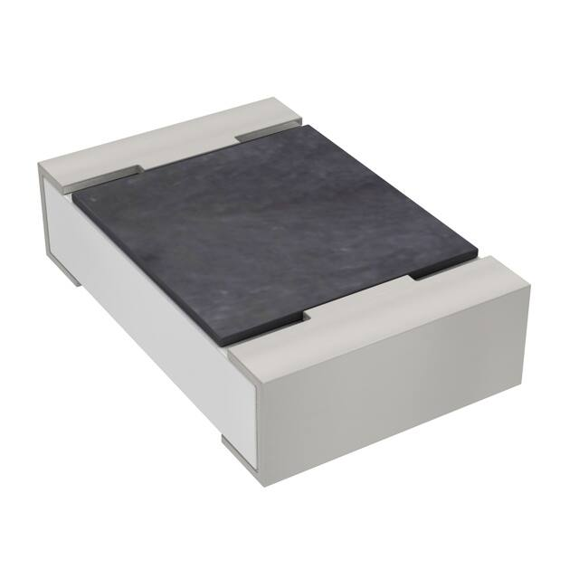
功能详解:文档详细描述了电阻器的构造,包括由高等级陶瓷体、内部金属电极、电阻材料层和保护涂层组成。电阻层通过激光切割来调整电阻值,并在外部加上纯锡端子。
应用信息:虽然文档没有直接提到具体的应用场景,但贴片电阻广泛应用于电子电路中,用于限制电流、分压、匹配阻抗等。
封装信息:提供了不同尺寸的电阻器的详细尺寸数据,包括长度、宽度、高度和内引脚间距。还提供了不同尺寸电阻器的卷带封装信息,包括卷带宽度、卷轴直径等。