DATA SHEET
HIGH POWER CHIP RESISTORS
RC high power series
5%, 1%
sizes 0603/0805/1206/2512
Product specification – Dec 14, 2010 V.0 Supersedes Date of Mar. 06, 2003
RoHS compliant & Halogen free
�Product specification
Chip Resistor Surface Mount
RC-High power
2
8
0603 to 2512
SERIES
SCOPE
ORDERING INFORMATION - GLOBAL PART NUMBER
This specification describes RC0603
to RC2512 high power chip resistors
with lead-free terminations made by
thick film process.
Both part numbers are identified by the series name, size, tolerance,
packaging type, temperature coefficient, taping reel, resistance value and
resistor terminal.
GLOBAL PART NUMBER (PREFERRED)
RC XXXX X X - XX XXXX L
APPLICATIONS
z All general purpose applications
(1)
(2) (3) (4) (5)
(6)
(7)
(1) SIZE
0603 / 0805 / 1206 / 2512
FEATURES
z Halogen Free Epoxy
z
(2) TOLERANCE
F = ±1%
J = ±5%
RoHS compliant
-
-
Products with lead-free
terminations meet RoHS
requirements
Pb-glass contained in electrodes,
resistor element and glass are
exempted by RoHS
z
Reducing environmentally
hazardous wastes
z
High component and equipment
reliability
z
Saving of PCB space
z
None forbidden-materials used in
products/production
(3) PACKAGING TYPE
R = Paper taping reel
K = Embossed taping reel
(4) TEMPERATURE COEFFICIENT OF RESISTANCE
– = Base on spec
(5) TAPING REEL
7W = 2 x standard power
(6) RESISTANCE VALUE
There are 2~4 digits indicated the resistor value. Letter R/K/M is decimal point, no need
to mention the last zero after R/K/M, e.g.1K2, not 1K20.
Detailed resistance rules show in table of “Resistance rule of global part number”.
(7) OPTIONAL CODE
Letter L is system default code for ordering only (Note)
Resistance rule of global part
number
Resistance coding rule
Example
0R
0R = Jumper
XRXX
(1 to 9.76 Ω)
1R = 1 Ω
1R5 = 1.5 Ω
9R76 = 9.76 Ω
XXRX
(10 to 97.6 Ω)
10R = 10 Ω
97R6 = 97.6 Ω
XXXR
(100 to 976 Ω)
100R = 100 Ω
XKXX
(1 to 9.76 KΩ)
1K = 1,000 Ω
9K76 = 9760 Ω
XMXX
(1 to 9.76 MΩ)
1M = 1,000,000 Ω
9M76= 9,760,000 Ω
ORDERING EXAMPLE
The ordering code of a RC2512
chip resistor, value 47 X, 2W
with ±5% tolerance, supplied in
7-inch tape reel is: RC2512JR7W47RL.
NOTE
1. All our RSMD products are RoHS
compliant and Halogen free. "LFP" of the
internal 2D reel label states "Lead-Free
Process"
2. On customized label, "LFP" or specific
symbol can be printed
www.yageo.com
Dec 14, 2010 V.0
�Product specification
Chip Resistor Surface Mount
RC-High power
SERIES
3
8
0603 to 2512
MARKING
RC0603/0805/1206/2512
E-24 series: 3 digits for 5%
03
YNSC001
Fig. 1
Value=10 KΩ
First two digits for significant figure and 3rd digit for number of zeros
Both E-24 and E-96 series: 4 digits for 1%
00
YNSC004
Fig. 2 Value=10 KΩ
First three digits for significant figure and 4th digit for number of zeros
For further marking information, please see special data sheet “Chip resistors marking”.
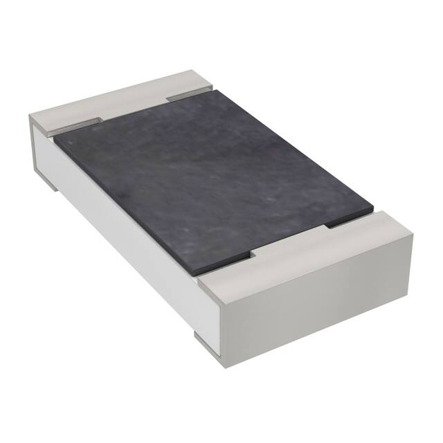
CONSTRUCTION
The resistor is constructed on top of a high-grade
ceramic body. Internal metal electrodes are added
on each end to make the contacts to the thick film
resistive element. The composition of the resistive
element is a noble metal embedded into a glass and
covered by a second glass to prevent environmental
influences. The resistor is laser trimmed to the rated
resistance value. The resistor is covered with a
protective epoxy coat, finally the two external
terminations (matte tin on Ni-barrier) are added.
See fig. 3.
OUTLINES
For dimension see Table 1
marking layer
overcoat
Primary glass layer
resistive layer
(Jumper chip is a conductor)
inner electrode
H
termination (Ni/matte tin)
ceramic substrate
I2
overcoat
I1
DIMENSIONS
Table 1 For outlines see fig. 3
TYPE
L (mm) W (mm)
W
H (mm)
I1 (mm)
I2 (mm)
RC0603 1.60 ±0.10 0.80 ±0.10 0.45 ±0.10 0.25 ±0.15 0.25 ±0.15
RC0805 2.00 ±0.10 1.25 ±0.10 0.50 ±0.10 0.35 ±0.20 0.35 ±0.20
RC1206 3.10 ±0.10 1.60 ±0.10 0.55 ±0.10 0.45 ±0.20 0.40 ±0.20
YNSC066
L
Fig. 3 Chip resistor outlines
RC2512 6.35 ±0.10 3.10 ±0.15 0.55 ±0.10 0.60 ±0.20 0.50 ±0.20
www.yageo.com
Dec 14, 2010 V.0
�Product specification
Chip Resistor Surface Mount
RC-High power
4
8
0603 to 2512
SERIES
ELECTRICAL CHARACTERISTICS
Table 2
TYPE
RC0603
RC0805
RC1206
Resistance Range
Operating
Temperature Range
1 Ω ≤ R ≤ 10 KΩ
1 Ω ≤ R ≤ 1 MΩ
RC2512
–55 °C to +155 °C
1 Ω ≤ R ≤ 150Ω
Power
Max.
Dielectric
Max.
Temperature
Rating Working Vol. Withstand Vol. Overload Vol. Coefficient of Resistance
1/5 W
50 V
100 V
100 V
1/4 W
150 V
300 V
300 V
1/2 W
200 V
400 V
500 V
2W
200 V
400 V
500 V
±200 ppm/°C
FOOTPRINT AND SOLDERING PROFILES
For recommended footprint and soldering profiles, please see the special data sheet “Chip resistors mounting”.
PACKING STYLE AND PACKAGING QUANTITY
Table 3 Packing style and packaging quantity
PACKING STYLE
REEL DIMENSION
RC0603
RC0805
RC1206
RC2512
7" (178 mm)
5,000
5,000
5,000
---
10" (254 mm)
10,000
10,000
10,000
---
13" (330 mm)
20,000
20,000
20,000
---
7" (178 mm)
---
---
---
4,000
Paper taping reel (R)
Embossed taping reel (K)
NOTE
1. For paper/embossed tape and reel specification/dimensions, please see the special data sheet “Chip resistors packing”.
FUNCTIONAL DESCRIPTION
OPERATING TEMPERATURE RANGE
handbook, halfpage
Range: –55 °C to +155 °C
P
(%Prated )
POWER RATING
100
Each type rated power at 70 °C:
RC0603=1/5 W; RC0805=1/4 W; RC1206=1/2 W;
RC2512=2 W
50
RATED VOLTAGE
The DC or AC (rms) continuous working voltage
corresponding to the rated power is determined by
the following formula:
V = √(P X R)
MLB206_2
0
55
0
50
70
100
155
o
Tamb ( C)
Fig. 4 Maximum dissipation (P) in percentage of rated power as a
function of the operating ambient temperature (Tamb)
Where
V = Continuous rated DC or AC (rms) working voltage (V)
P = Rated power (W)
R = Resistance value (X)
www.yageo.com
Dec 14, 2010 V.0
�Product specification
Chip Resistor Surface Mount
RC-High power
SERIES
5
8
0603 to 2512
TESTS AND REQUIREMENTS
Table 4 Test condition, procedure and requirements
TEST
TEST METHOD
PROCEDURE
REQUIREMENTS
Temperature
Coefficient of
Resistance
(T.C.R.)
IEC 60115-1 4.8
At +25/–55 °C and +25/+125 °C
Refer to table 2
Formula:
R2–R1
T.C.R= ------------------------- ×106 (ppm/°C)
R1(t2–t1)
Where
t1=+25 °C or specified room temperature
t2=–55 °C or +125 °C test temperature
R1=resistance at reference temperature in ohms
R2=resistance at test temperature in ohms
Life/Endurance
IEC 60115-1 4.25.1
High
Temperature
Exposure/
Endurance at
Upper Category
Temperature
IEC 60068-2-2
Moisture
Resistance
MIL-STD-202G Method-106G
At 70±5 °C for 1,000 hours, RCWV applied for
1.5 hours on, 0.5 hour off, still air required
±(1.0%+0.05 Ω) for 1% tol.
1,000 hours at 155±5 °C, unpowered
±(1.0%+0.05 Ω) for 1% tol.
±(3.0%+0.05 Ω) for 5% tol.
±(2.0%+0.05 Ω) for 5% tol.
Each temperature / humidity cycle is defined at 8
hours, 3 cycles / 24 hours for 10d. with 25 °C /
65 °C 95% R.H, without steps 7a & 7b,
unpowered
±(0.5%+0.05 Ω) for 1% tol.
±(2.0%+0.05 Ω) for 5% tol.
Parts mounted on test-boards, without
condensation on parts
Measurement at 24±2 hours after test conclusion
Thermal Shock
MIL-STD-202G Method-107G
-55/+125 °C
±(0.5%+0.05 Ω) for 1% tol.
Number of cycles required is 300. Devices
unmounted
±(1%+0.05 Ω) for 5% tol.
Maximum transfer time is 20 seconds. Dwell time
is 15 minutes. Air – Air
Short Time
Overload
IEC60115-1 4.13
2.5 times of rated voltage or maximum overload
voltage whichever is less for 5 sec at room
temperature
±(1.0%+0.05 Ω) for 1% tol.
±(2.0%+0.05 Ω) for 5% tol.
No visible damage
www.yageo.com
Dec 14, 2010 V.0
�Product specification
Chip Resistor Surface Mount
RC-High power
SERIES
6
8
0603 to 2512
TEST
TEST METHOD
PROCEDURE
REQUIREMENTS
Board Flex/
Bending
IEC 60068-2-21
Chips mounted on a 90mm glass epoxy resin
PCB (FR4)
±(1.0%+0.05 Ω) for 1%, 5% tol.
No visible damage
5 mm bending
Bending time: 60±5 seconds
Low
Temperature
Operation
IEC 60068-2-1
The resistor shall be subjected to a DC rated
voltage for 1.5 h-on, 0.5 h-off, at -55±3 °C
±(0.5%+0.05 Ω) for 1% tol.
This constitutes shall be repeated for 96 hours
No visible damage
±(1.0%+0.05 Ω) for 5% tol.
However the applied voltage shall not exceed
the maximum operating voltage
Insulation
Resistance
IEC 60115-1 4.6
Rated continuous overload voltage (RCOV)
for 1 minute
≥10 GΩ
Dielectric
Withstand
Voltage
IEC 60115-1 4.7
Maximum voltage (Vrms) applied for 1 minute
No breakdown or flashover
Resistance to
Solvent
IPC/JEDEC J-STD-020D
lsopropylalcohol (C3H7OH) followed by
brushing
No smeared
Maximum voltage (Vrms) applied
Resistors range
Value
R < 100 Ω
10 dB
100 Ω ≤ R < 1 KΩ
20 dB
1 KΩ ≤ R < 10 KΩ
30 dB
10 KΩ ≤ R < 100 KΩ
40 dB
100 KΩ ≤ R < 1 MΩ
46 dB
Noise
IEC 60115-1 4.12
Biased Humidity
(steady state)
IEC 60115-1 4.37
Intermittent
Overload
IEC 60115-1 4.39
Steady state for 1000 hours at 40 °C / 95% R.H.
RCWV applied for 1.5 hours on and
0.5 hour off
±(1.0%+0.05 Ω) for 1% tol.
2.5 times of rated voltage or maximum overload
voltage whichever is less for 1 second on and 25
seconds off; total 10,000 cycles
±(1.0%+0.05 Ω) for 1% tol.
±(2.0%+0.05 Ω) for 5% tol.
±(2.0%+0.05 Ω) for 5% tol.
www.yageo.com
Dec 14, 2010 V.0
�Product specification
Chip Resistor Surface Mount
RC-High power
SERIES
7
8
0603 to 2512
TEST
TEST METHOD
PROCEDURE
REQUIREMENTS
Solderability
- Wetting
IPC/JEDEC J-STD-002B test B
Electrical Test not required
Well tinned (≥95% covered)
Magnification 50X
No visible damage
SMD conditions:
1st step: method B, aging 4 hours at 155 °C
dry heat
2nd step: lead-free solder bath at 245±3 °C
Dipping time: 3±0.5 seconds
- Leaching
IPC/JEDEC J-STD-002B test D
Lead-free solder, 260 °C, 30 seconds
immersion time
No visible damage
- Resistance to
Soldering Heat
IEC 60068-2-58
Condition B, no pre-heat of samples
±(0.5%+0.05 Ω) for 1% tol.
Lead-free solder, 260 °C, 10 seconds
immersion time
±(1.0%+0.05 Ω) for 5% tol.
No visible damage
Procedure 2 for SMD: devices fluxed and
cleaned with isopropanol
www.yageo.com
Dec 14, 2010 V.0
�Product specification
Chip Resistor Surface Mount
RC-High power
SERIES
0603 to 2512
8
8
REVISION HISTORY
REVISION DATE
Version 0
CHANGE NOTIFICATION
Dec 14, 2010 -
DESCRIPTION
- First issue of this specification
“ Yageo reserves all the rights for revising the content of this datasheet without further notification, as long as the products itself are unchanged. Any
product change will be announced by PCN.”
www.yageo.com
Dec 14, 2010 V.0
�


 工商网监
湘ICP备2023018690号
工商网监
湘ICP备2023018690号
