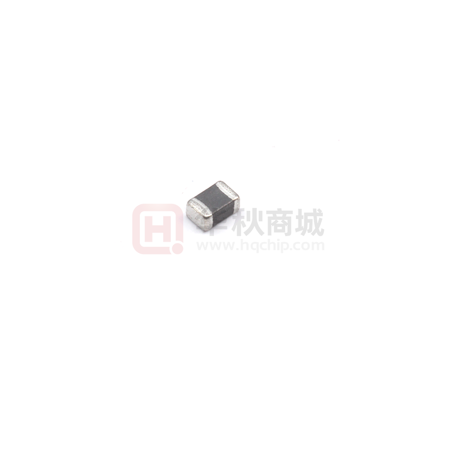
Approval Sheet
WLFM_C
Multi-Layer Power Inductor
*Contents in this sheet are subject to change without prior notice.
Page 1 of 7
ASC_WLFM_C Series
Jul.2020
�Approval Sheet
Features
1.
General purpose chip ferrite power inductor for high integration electronics device.
2.
Ceramic structure provides high reliability、high productivity.
3.
Low DC resistance with high current.
4.
RoHS compliance.
Applications
1.
DC line filter, DC/DC inductor.
2.
Suitable for DVD,DSC,PND,PC,NB,Power Line.
Shape and Dimension
L
T
W
B
Unit: mm (inches)
WLFM
B
L
W
T
WLFM201209
2.00±0.20
1.25±0.20
0.90±0.10
0.50±0.30
WLFM201609
2.00±0.20
1.60±0.20
0.90±0.10
0.50±0.30
WLFM252009
2.50±0.20
2.00±0.20
0.90±0.10
0.50±0.30
Series
(Min/Max)
Ordering Information
WL
FM
2012
Product
Code
Series
Dimensions
WL:
Inductor
Multilayer
2012:EIA 0805
2016:EIA 0806
2520:EIA 1008
Page 2 of 7
09
Thickness
09= 0.9mm
M
R47
P
Tolerance
Value
Packing Code
M: ± 20%
R47=0.47uH
P=7” Reeled
(Embossed tape)
2R2=2.2uH
ASC_WLFM_C Series
C
C
General
Jul.2020
�Approval Sheet
Electrical Characteristics
WLFM_C Series
Walsin Part Number
L(uH)
Inductance
Tolerance
Test
Freq
(MHz)
RDC
DC Resistance (Ω
Ω)
Max.
Rated
Current
(mA)
SRF
(MHz)
WLFM201209M1R0PC
1.00
±20%
1
0.10
1100
90
WLFM201209M2R2PC
2.20
±20%
1
0.17
900
70
WLFM201209M3R3PC
3.30
±20%
1
0.20
800
50
WLFM201209M4R7PC
4.70
±20%
1
0.23
800
40
Walsin Part Number
L(uH)
Inductance
Tolerance
Test
Freq
(MHz)
RDC
DC Resistance (Ω
Ω)
Max.
Rated
Current
(mA)
SRF
(MHz)
WLFM201609M2R2PC
2.20
±20%
1
0.12
1100
40
WLFM201609M4R7PC
4.70
±20%
1
0.16
900
20
Walsin Part Number
L(uH)
Inductance
Tolerance
Test
Freq
(MHz)
RDC
DC Resistance (Ω
Ω)
Max.
Rated
Current
(mA)
SRF
(MHz)
WLFM252009MR47PC
0.47
±20%
1
0.04
1800
100
WLFM252009M1R0PC
1.00
±20%
1
0.055
1600
60
WLFM252009M1R5PC
1.50
±20%
1
0.07
1500
50
WLFM252009M2R2PC
2.20
±20%
1
0.08
1300
40
WLFM252009M3R3PC
3.30
±20%
1
0.10
1200
30
WLFM252009M4R7PC
4.70
±20%
1
0.11
1100
25
WLFM252009M6R8PC
6.80
±20%
1
0.20
1100
25
*1:For special part number which is not shown in the above table, please refer to appendix.
*2:Apply DC 0.4 ~ 0.6A to chip for 1 ~ 3 sec. before to measure inductance.
Test Instrument:
:
•HP4291B-RF Impedance / Material Analyzer
•HP4338A/B Milliohm meter
•Test Frequency : 1MHz / OSC Level : 100mV
Page 3 of 7
ASC_WLFM_C Series
Jul.2020
�Approval Sheet
General Technical Data
Operating temperature range : - 40℃ ~ +85℃
Storage Condition : Less than 40℃ and 70% RH
Storage Time : 12 months Max.
Soldering method : Reflow
Land Patterns for Reflow Soldering
Size(mm)
A
B
C
2012
1.0 ~ 1.2
3.0 ~ 4.0
0.8 ~ 1.1
2016
1.0 ~ 1.2
3.0 ~ 4.0
1.0 ~ 1.5
2520
1.2~1.5
3.5~4.0
1.5~2.0
Page 4 of 7
ASC_WLFM_C Series
Jul.2020
�Approval Sheet
Reliability and Test Conditions
Test item
Test condition
Criteria
1.More than 95 % of terminal
electrode should be covered with
new solder
Resistance to Solder Heat
Solder temperature : 260 ± 5℃
2.No mechanical damage
Flux : Rosin
3.Inductance value should be within
± 20 % of the initial value
DIP time : 10 ± 1 sec
* Apply DC 0.4 ~ 0.6A to chip for 1 ~
3 sec. before to measure
inductance.
Solder temperature : 235 ± 5℃
Solderability
Flux : Rosin
3. DIP time : 5 ± 1 sec
Adhesive Test
1. More than 95 % of terminal
electrode should be covered with
new solder
2. No mechanical damage
Reflow temperature : 245℃ It shall be
Soldered on the substrate applying direction 1. No mechanical damage
parallel to the substrate
2. Soldering the products on PCB
Apply force(F) : 5 N
after the pulling test force > 5 N
Test time : 10 sec
Temperature:-40 ~ 85℃ For 30 minutes
each
Temperature Cycle
Cycle: 100 cycles
Measurement:At ambient temperature 24
hours after test completion
1.No mechanical damage
2.Inductance should be within ±20%
of the initial value
* Apply DC 0.4 ~ 0.6A to chip for 1 ~
3 sec. before to measure
inductance.
1. No mechanical damage
Temperature: 85 ± 5℃
High Temperature
Resistance
Humidity
Testing time: 1000 hrs
Measurement: at ambient temperature 24
hours after test completion
* Apply DC 0.4 ~ 0.6A to chip for 1 ~
3 sec. before to measure
inductance.
Temperature: 40℃ ± 2℃
1.No mechanical damage
Humidity: 90-95 % RH
2.Inductance should be within ±20%
of the initial value
Testing time: 1000 hrs
Measurement:At ambient temperature 24
hours after test completion
At ambient temperature & humidity
Rated Current
Page 5 of 7
2. Inductance should be within ±20%
of the initial value
Testing time:5 minutes ( under full rated
current )
ASC_WLFM_C Series
* Apply DC 0.4 ~ 0.6A to chip for 1 ~
3 sec. before to measure
inductance.
:
WLFM product surface temp
below room temperature plus 40℃
Jul.2020
�Approval Sheet
Tape and Reel Specifications
Plastic Carries(E)
Paper Carrier(P)
Taping Dimensions
(mm)
Symbol
W
P
E
F
D
D1
Po
10Po
P2
Ao
Bo
Ko(T)
t
Page 6 of 7
2012
E
8.00 ± 0.10
4.00 ± 0.10
1.75 ± 0.10
3.50 ± 0.10
1.55 ± 0.05
1.00 ± 0.05
4.00 ± 0.10
40.0 ± 0.20
2.00 ± 0.10
1.40 ± 0.10
2.30 ± 0.10
1.13 ± 0.10
0.22 ± 0.05
2016
E
8.00 ± 0.10
4.00 ± 0.10
1.75 ± 0.10
3.50 ± 0.10
1.55 ± 0.05
1.00 ± 0.05
4.00 ± 0.10
40.0 ± 0.20
2.00 ± 0.10
1.80 ± 0.10
2.20 ± 0.10
1.15 ± 0.10
0.22 ± 0.05
2520
E
8.00 ± 0.10
4.00 ± 0.10
1.75 ± 0.10
3.50 ± 0.10
1.55 ± 0.05
1.00 ± 0.05
4.00 ± 0.10
40.0 ± 0.20
2.00 ± 0.10
2.25 ± 0.10
2.80 ± 0.10
1.35 ± 0.10
0.22 ± 0.05
ASC_WLFM_C Series
Jul.2020
�Approval Sheet
Reel Dimensions
7” Reel Packaging Quantity
PART SIZE
(EIA SIZE)
Qty.(pcs)
BOX
2012
(0805)
3,000
2016
(0806)
3,000
2520
(1008)
3,000
5 reels / inner box 5 reels / inner box 5 reels / inner box
Recommended Soldering Conditions
Page 7 of 7
ASC_WLFM_C Series
Jul.2020
�
很抱歉,暂时无法提供与“WLFM201209M2R2PC”相匹配的价格&库存,您可以联系我们找货
免费人工找货- 国内价格
- 50+0.10313
- 200+0.09630
- 600+0.08947
- 2000+0.08264
- 5000+0.07581
- 10000+0.07103
