DATA BOOK
Thin Film Components
Low R-Value
Thin Film Chip Resistors
SUSUMU CO.,LTD.
�Low R-Value Thin Film Chip Resistors(Resistor for current detection)
Structure
Protection film
Resistance film
Electrode
Wrap around electrode
Alumina substrate
Features
▪ Excellent heat split structure (Patent No.2963671) and compact size for lowering surface temperature rising.
▪ A tight resistance tolerance of�1% and an excellent TCR of�100ppm/�C assure current sensing accuracy.
Specifications
Dimension
(mm)
RL3720
L
3.75�0.30
3.75�0.30
7.50�0.30
7.50�0.30
W
2.00�0.20
2.00�0.20
2.00�0.20
2.00�0.20
P
0.40�0.20
0.40�0.20
0.40�0.20
0.40�0.20
T
0.40�0.10
0.40�0.15/�0.10
0.40�0.10
0.40�0.15/�0.10
Dimension
(mm)
RL0510
(0402)
RL3720W
RL7520
RL1220
(0805)
RL1632
(1206)
RL7520W
L
P
W
T
RL3264
(2412)
L
1.00�0.10
2.00�0.02
3.20�0.20
6.40�0.20
W
0.50�0.10
1.25�0.20
1.60�0.20
3.20�0.20
P
0.20�0.10
0.40�0.20
1.00�0.15
2.00�0.15
T
0.35�0.10
0.40�0.10
0.50�0.15
0.50�0.15
W
P
L
T
electric characteristics
Type
Power
RL3720
RL3720W
RL7520
1/2W
1W
1W
2W
Resistance Tolerance
�1%(F)
�2%(G)
�1%(F)
�2%(G)
�1%(F)
�2%(G)
�1%(F)
�2%(G)
(code)
RL7520W
Resistance range (ohm) 0.022�0.075
0.1�2.2
0.010�0.068
0.1�1.0
0.010�0.075
0.1�1.0
5,6,9m� 0.010�0.068 0.1�0.47
Temperature Coefficient
of Resistance (ppm/�C)
0��200
(S)
0��350
(T)
0��200
(S)
0��350
(T)
0��200
(S)
0��420
(T)
Resistance Values
0��350
(T)
E�6
E�6
Package
RL0510
(0402)
Type
Power
1/8W
Resistance Tolerance
(code)
�1%(F)
�2%(G)
RL1632
(1206)
1/4W
1/2W
1W
1%
(F)
�%
(F)
�2%(G)
�5%(J)
�1%(F)
�2%(G)
0.1�4.7
0.022�0.068 0.1�10.0
Temperature Coefficient
of Resistance (ppm/�C)
0��200
(S)
0��350 0��200
(T)
(S)
�100
(R)
E�12
E�6
E�6
10,000pcs/reel
▪ Please call for TCR's less than �100ppm/�C
Package
▪ Kevin four termination current sensor is available
0��200
(S)
E�6
E�6
4000pcs/reel
RL1220
(0805)
Referance range(ohm)
Resistance Values
0��350
(T)
RL3264
(2412)
0.068�0.47 0.018�0.027 0.033�0.047 0.056�0.47 0.018�0.027 0.033�0.047 0.056�0.47
0��350 0��200
(T)
(S)
E�6
5000pcs/reel
�100
(R)
0��350 0��200
(T)
(S)
E�6
�100
(R)
�Application
Typically used with control IC for power supply protection circuits, charging/discharging
control circuits of battery-packages, and motor control circuits.
�For power supply protection and motor control application
(1) A protection circuit
(2) To control the current and function
Power supply: To control the charge or discharge current and stabilize load.
Motor: To control the rotation speed, either steady or variable.
protection circuits
Load
Re : Current sensor
When loading current is low, current flows in direction 1. When
loading current is increased to a certain level and turns Tr2 on,
Tr1
current flows in direction 2 and turns off Tr1.
1
Let Re be 0.2 ohm:
When I is 1 ampere, voltage between B and E is 0.2 volt.
When I is 2 amperes, voltage between B and E is 0.4 volts.
B Ι
2
Tr2
When I is 3 amperes, voltage between B and E is 0.6 volts and
turns Tr2 on.
Re
E
�Compare to conventional type low ohmic chip resistors, the structure of this RL-series has higher thermal dissipation (patent No 2963671)
rate, able to assure lower surface temperature rising and lower thermal effect on surrounding parts. Strongly recommended component.
control circuit
Rf
A basic voltage-to-current converter
Assume Vi is the input voltage on the current sensor, then output
R1
R2
current Io could be formulated as follows:
Ιo
Rs
Ι o�
input voltage
Vi
Load
R3
Vi�Rf
R1�Rs
The output current is controllable and independent of load R.
�15V
�Excellent initial characteristics, large heat dissipation, low temperature rise and excellent temperature characteristics assure high
accuracy, contributing to longevity of battery packages.
DATA
�Resistance Distribution
n�50
2.0
1.0
0.5
0
�0.5
R10
2R2
�1.0
4R7
Resistance tolerance (%)
Resistance tolerance (%)
1.5
Assurance range
n�50
3.0
2.0
Assurance range
Referance range
1.0
0
�1.0
R10
R022
�2.0
�1.5
�3.0
�2.0
RL0510
RL1220
1R0
�n�50
1.5
1.0
Assurance range
0.5
0
R033
R068
R47
�0.5
�1.0
n�50
2.0
Resistance tolerance (%)
Resistance tolerance (%)
2.0
1.5
1.0
Assurance range
0.5
0
R033
�1.0
�1.5
�1.5
�2.0
�2.0
RL1632
RL3264
n�50
1.5
Assurance range
0.5
0
�0.5
R01
R022
1R0
�1.0
n�50
2.0
Resistance tolerance (%)
Resistance tolerance (%)
2.0
1.0
R47
R068
�0.5
�1.5
1.5
1.0
Assurance range
0.5
0
�0.5
R005
R10
R01
�1.0
�1.5
�2.0
�2.0
RL3720,RL3720W
RL7520,RL7520W
R005 is for RL7250W only
n�50
300
200
Assurance range
R10
100
2R2
4R7
0
Temperature Coefficicient of Resistance (ppm/�C)
Temperature Coefficicient of Resistance (ppm/�C)
�Temperature Coefficicient of Resistance Distribution
�100
n�50
300
Assurance range
200
100
0
Assurance range
�100
�200
n�50
Assurance range
Assurance range
R033
R068
0
�100
�200
RL1632
R47
Temperature Coefficicient of Resistance (ppm/�C)
Temperature Coefficicient of Resistance (ppm/�C)
RL1220
300
100
1R0
R10
Low TCR
RL0510
200
R10
n�50
300
200
100
Assurance range
Assurance range
R033
R068
0
�100
�200
RL3264
R47
�Temperature Coefficicient of Resistance (ppm/�C)
Temperature Coefficicient of Resistance (ppm/�C)
n�50
400
Assurance range (Guaranteed range)
350
300
250
Assurance range (Guaranteed range)
200
R022
150
100
R01
1R0
50
0
�50
450
n�50
Assurance range (Guaranteed range)
400
Assurance range (Guaranteed range)
350
300
R005
250
Assurance range (Guaranteed range)
200
150
R01
100
R10
50
0
�50
RL7520,RL7520W
RL3720,RL3720W
R005 is for RL7250W only
Pad size (S)�W�L
Dimension W
200
180
Chip resistance
160
Dimension L
(27mm)
140
120
apply 1 watt
100
land patterns
80
60 apply 0.75 watt
40
apply 0.5 watt
20
0
0
5
10
15
20
25
Dimension W (mm)
Differential increase in surface temperature (�C)
RL3720W(Rated 1W)
300
Dimension W
(4.15mm)
250
apply 0.5 watt
200
Chip resistance
150
Dimension L
land patterns
apply 0.25 watt
100
50
0
0
10
RL3720W(Rated 0.5W)
Differential increase in surface temperature (�C)
220
20
30
Dimension L (mm)
220
Dimension W
Pad size (S)�W�L
200
Chip resistance
180
160
Dimension L
(27mm)
land patterns
140
apply 2 watt
120
100
80
apply 1 watt
60
40
apply 0.5 watt
20
0
0
5
10
15
20
25
Dimension W (mm)
RL7520W(Rated 2W)
Differential increase in surface temperature (�C)
Differential increase in surface temperature (�C)
�This low resistance chip resistor is designed to have better heat (generated by resistor) dissipation rate than the copper pad on
board, therefor surface temperature rising on the resistor depends on the pad's on PC board.
300
Dimension W
(7.9mm)
250
200
150
apply 1 watt
apply
0.75 watt
apply
0.5 watt
Chip resistance
Dimension L
land patterns
100
apply 0.25 watt
50
0
0
10
RL7520(Rated 1W)
20
30
Dimension L (mm)
�
Apply a pulse to a sample resistor and measure the rate of resistance
change. Raise the voltage gradually until the rate of resistance change
exceeds �0.5%. The threshold pulse voltage is defined as the upper limit
voltage to hold the rate of resistance change within 60.5%.
Low ohmic resistor receive internally the effects of thermal electromotive
force. We minimize the effects of thermal electromotive force of our low
ohmic resistors through thin film technology. The effect of thermal
electromotive power could be detected by measuring polarization of its
resistance values.
200
Changes in resistance value (�)
RL7520W-R10
RL7520-R10
150
Limit voltage (W)
Sample:RL7520-R10-F
0.02
100 RL3264-R050
RL3720-R075
RL1632-R050
50
RL1220-R10
0
0.001
0.01
0.1
pulse width (sec)
1
10
0.015
0.01
0.005
3A
25�C
0
�0.005
�0.01
�0.015
�0.02
2A
70�C
2A
0�C
3A
70�C
3A
0�C
2A
25�C
resistance polarization
Reliability Test DATA
Compared with general-purpose resistors, low resistance resistors are more often used in high temperature environment
and high power applications where the amount of heat is high. High reliability is necessary. Susumu's low ohmic
resistors have excellent reliability of less than 0.01fit.
�Load Life Test
Test conditons:70�C Apply rated voltage for 90 minutes followed by 30 minute intermission. This cycle is repeated for 1,000 hours.
Ta�70�C
Sample:RL7520WT-R033-F (n�20pcs)
Ta�70�C
Sample:RL1220T-R022-J (n�20pcs)
1.0
Referance change (%)
Referance change (%)
1.0
0.0
�1.0
10
100
1000
10000
0.0
�1.0
10
100
1000
10000
Time (hrs)
Time (hrs)
�Moisture Load Life Test
Test conditons:40�C,95%RH
Ta�40�C,95%RH
Sample:RL1220T-R068-J (n�20pcs)
1.0
Referance change (%)
Referance change (%)
1.0
Apply rated voltage for 90 minutes followed by 30 minute intermission. This cycle is repeated for 1,000 hours.
Ta�40�C,95%RH
Sample:RL7520WT-R022-F (n�20pcs)
0.0
�1.0
10
100
1000
Time (hrs)
10000
0.0
�1.0
10
100
1000
Time (hrs)
10000
�Recommended land patterns
�Recommended land patterns
Board thickness:1.6mm,Board material:glass fabric epoxy resin,Copper film thickness:0.035mm
Solder resist coating
land
Solder resist coating
land
Chip resistor
Chip resistor
0.7
2.4
0.6
1.0
1.9
4.0
RL0510 Recommended land pattern
land
Terminal for
voltage measurement
Chip resistor
0.5
RL1220 Recommended land pattern
Terminal for
voltage measurement
Chip resistor
0.5
land
Solder resist coating
1.7
Solder resist coating
3.3
1.1
2.3
4.7
7.9
RL1632 Recommended land pattern
RL3264 Recommended land pattern
�Long-side electrode type Recommended land patterns
land
voltage measurement line
Solder resist coating
c
b
a
RL3720
RL3720W
RL7520
RL7520W
a
b
c
d
27.0
27.0
27.0
27.0
4.0
4.0
4.0
4.0
1.2
1.2
1.2
1.2
4.2
7.9
7.9
15.8
dimension:mm
d
chip Resistor
�
很抱歉,暂时无法提供与“RL3720S-R22-G”相匹配的价格&库存,您可以联系我们找货
免费人工找货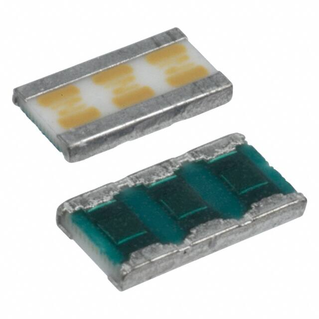


 工商网监
湘ICP备2023018690号
工商网监
湘ICP备2023018690号
