Features
■ Radial Leaded Devices
■ Cured, flame retardant epoxy polymer
insulating material meets
UL 94V-0 requirements
■ Bulk packaging,or tape and reel
available on most models
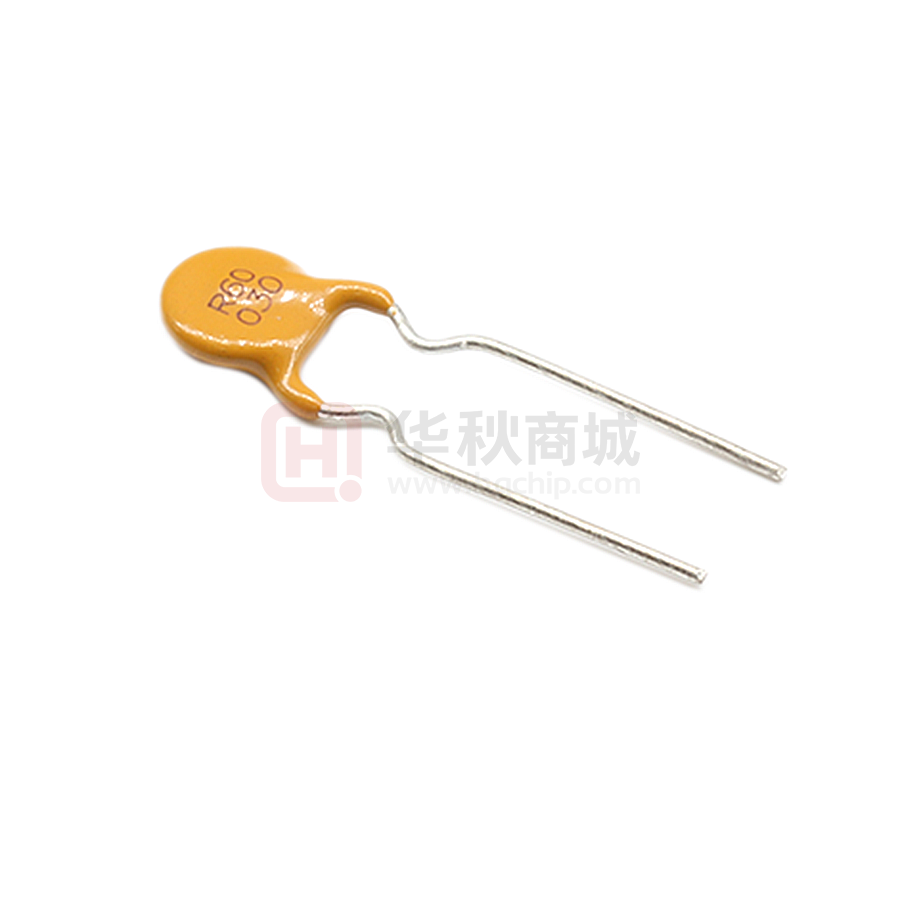
R60 Series
Applications
Almost anywhere there is a low voltage
power supply, up to 60V and a load to be
protected, including:
■ Industrial controls
■ Automotive electronics
■ Medical products
Alpha-Top (Sea & Land Alliance)
Electrical Properties
Model
R60-005
R60-010
R60-017
R60-020
R60-025
R60-030
R60-040
R60-050
R60-065
R60-075
R60-090
R60-110
R60-135
R60-160
Vmax
(Vdc)
60
60
60
60
60
60
60
60
60
60
60
60
60
60
Imax
(A)
40
40
40
40
40
40
40
40
40
40
40
40
40
40
Ihold
(A)
0.05
0.10
0.17
0.20
0.25
0.30
0.40
0.50
0.65
0.75
0.90
1.10
1.35
1.60
Itrip
(A)
0.10
0.20
0.34
0.40
0.50
0.60
0.80
1.00
1.30
1.50
1.80
2.20
2.70
3.20
Pd
Typ.
(W)
0.38
0.38
0.48
0.41
0.45
0.49
0.56
0.77
0.88
0.92
0.99
1.50
1.70
1.90
Maximum
Time To Trip
Current Time
(A)
0.25
0.50
0.85
1.00
1.25
1.50
2.00
2.50
3.25
3.75
4.50
5.50
6.75
8.00
(Sec)
5.0
4.0
3.0
2.2
2.5
3.0
3.8
4.0
5.3
6.3
7.2
8.2
9.6
11.4
Agency
Approval
Resistance
Rimin
Rimax
R1max
(W)
7.30
2.00
2.50
1.25
0.65
0.45
0.40
0.35
0.25
0.20
0.15
0.13
0.10
0.07
(W)
18.00
4.50
5.21
2.75
1.95
1.33
0.86
0.77
0.48
0.40
0.31
0.25
0.19
0.14
(W)
30.00
7.50
8.00
4.40
3.00
2.10
1.29
1.17
0.72
0.60
0.47
0.38
0.30
0.22
R60-185
60
40
1.85
3.70
2.10
9.25
12.6
0.06
0.12
R60-250
60
40
2.50
5.00
2.50
12.50
15.6
0.04
0.08
R60-300
60
40
3.00
6.00
2.80
15.00
19.8
0.03
0.06
R60-375
60
40
3.75
7.50
3.20
18.75
24.0
0.02
0.05
Ihold = Hold Current : maximum current device will sustain for 4 hours without tripping in 25°C still air.
Itrip = Trip Current : minimum current at which the device will trip in 25°C still air.
Vmax = Maximum voltage device can withstand without damage at rated current (I max).
0.19
0.13
0.10
0.08
Imax = Maximum fault current device can withstand without damage at rated voltage (V max).
Pd = Power dissipated from device when in the tripped state at 25°C still air.
Ri min/max = Minimum/Maximum resistance of device in initial (un-soldered) state.
R1 max = Maximum resistance of device at 25°C measured one hour after tripping.
CAUTION : Operation beyond the specified ratings may result in damage and possible arcing and flame.
Environmental Specifications
Test
Conditions
Passive aging
+85°C, 1000 hrs
Humidity aging
+85°C, 85% R.H.,1000 hrs
Thermal shock
+85°C to -40°C, 20 times
Resistance to solvent
MIL-STD-202,Method 215
Vibration
MIL-STD-202,Method 201
Ambient operating /storage conditions : - 40 °C to +85 °C
Maximum surface temperature of the device in the tripped state is 125 °C
In case of special use, please contact our engineer
Agency Approvals :
E201504(Alpha-Top)/E319079(Sea&Land)
R 50274672
Regulation/Standard:
2015/863/EU
EN14582
UL
TUV
√
√
√
√
√
√
√
√
√
√
√
√
√
√
√
√
√
√
√
√
√
√
√
√
√
√
√
√
√
√
√
√
√
√
�R60 Series
Alpha-Top (Sea & Land Alliance)
Physical Dimensions (Unit: mm)
R60-005
R60-010
R60-017
R60-020
R60-025
R60-030
R60-040
R60-050
R60-065
R60-075
R60-090
R60-110
R60-135
R60-160
A
Max.
7.4
7.4
7.4
7.4
7.4
7.4
7.6
7.9
9.7
10.4
11.7
13.0
14.5
16.3
B
Max.
12.7
12.7
12.7
12.7
12.7
13.0
13.5
13.7
14.5
15.2
15.8
18.0
19.6
21.3
C
Typ.
5.1
5.1
5.1
5.1
5.1
5.1
5.1
5.1
5.1
5.1
5.1
5.1
5.1
5.1
D
Min.
7.6
7.6
7.6
7.6
7.6
7.6
7.6
7.6
7.6
7.6
7.6
7.6
7.6
7.6
E
Max.
3.1
3.1
3.1
3.1
3.1
3.1
3.1
3.1
3.1
3.1
3.1
3.1
3.1
3.1
F
Max.
1.0
1.0
1.7
1.0
1.0
1.0
1.2
1.2
1.5
1.5
1.5
1.2
1.2
1.5
Lead
Style
Kink
Kink
Kink
Kink
Kink
Kink
Kink
Kink
Kink
Kink
Kink
Straight
Straight
Straight
R60-185
17.8
22.9
5.1
7.6
3.1
1.5
Straight
R60-250
R60-300
R60-375
21.3
24.9
28.5
26.4
30.0
33.5
10.2
10.2
10.2
7.6
7.6
7.6
3.1
3.1
3.1
1.7
2.0
2.0
Straight
Straight
Straight
Model
Dimensions
Marking
A
A
E
A
E
C
B
B
D
B
D
D
C
C
R60
135
XXXXY
F
= Trademark
R60 = Radial type 60 Vrms
135 = 1.35A hold current
XXXX = Date code
Y = Factory code
Physical Characteristics
Lead Material :
R60-010: Tin-plated nickel-copper alloy, 0.205mm2 (24AWG), Φ0.51mm(0.020 in).
R60-017 ~ 040: Tin-plated copper-clad steel, 0.205mm2 (24AWG), Φ0.51mm(0.020 in).
R60-050 ~ 090: Tin-plated copper , 0.205mm2 (24AWG), Φ0.51mm(0.020 in).
R60-110 ~ 375: Tin-plated copper , 0.52mm2 (20AWG), Φ0.81mm(0.032 in).
Lead Solderability : MIL-STD-202, Method 208
Order information
Packing
R60
Radial type
185
Hold
60 V
Current
(A)
K or S
K=Kink leads
R or U
R= Tape &
Model
R60-005 ~ R60-090
Reel Q'ty
3000
Bag Q'ty
500
S=Straight
leads
Reel
U= Bulk
packaged
R60-017
R60-110 ~ R60-185
R60-250 ~ R60-375
2500
1500
-
500
500
500
Devices taped with reference EIA468 standard.
�R60 Series
Alpha-Top (Sea & Land Alliance)
Typical time-to-trip curve at 25°C
Thermal derating curve
Average Time Current Curves
1000
Derating Curves for R60 Series
0.10A
3.75A
0.05A
0.17A
180
0.20A
0.25A
Percentage of Derated Current
160
0.30A
100
0.40A
TIME IN SECOND
0.50A
0.65A
10
0.75A
0.90A
1.10A
1
1.35A
1.60A
1.85A
0.1
2.50A
3.00A
140
120
100
80
60
40
20
3.75A
0
0.01
0.1
1
10
-40
100
-20
CURRENT IN AMPERES
0
20
40
60
80
Temperature (°C)
Ihold versus temperature
Model
Maximum ambient operating temperature (Tmao) vs. hold current (Ihold)
R60-005
R60-010
R60-017
R60-020
R60-025
-40°C
0.08
0.16
0.26
0.31
0.39
-20°C
0.068
0.14
0.23
0.27
0.34
0°C
0.06
0.12
0.20
0.24
0.30
25°C
0.05
0.10
0.17
0.20
0.25
40°C
0.04
0.08
0.14
0.16
0.20
50°C
0.036
0.07
0.12
0.14
0.18
60°C
0.032
0.06
0.11
0.13
0.16
70°C
0.027
0.05
0.09
0.11
0.14
85°C
0.02
0.04
0.07
0.08
0.10
R60-030
0.47
0.41
0.36
0.30
0.24
0.22
0.19
0.16
0.12
R60-040
R60-050
R60-065
R60-075
R60-090
R60-110
R60-135
R60-160
R60-185
R60-250
R60-300
R60-375
0.62
0.78
1.01
1.16
1.40
1.71
2.09
2.48
2.87
3.88
4.65
5.81
0.54
0.68
0.88
1.02
1.22
1.50
1.84
2.18
2.52
3.40
4.08
5.10
0.48
0.60
0.77
0.89
1.07
1.31
1.61
1.90
2.20
2.98
3.57
4.46
0.40
0.50
0.65
0.75
0.90
1.10
1.35
1.60
1.85
2.50
3.00
3.75
0.32
0.41
0.53
0.61
0.73
0.89
1.09
1.30
1.50
2.03
2.43
3.04
0.29
0.36
0.47
0.54
0.65
0.79
0.97
1.15
1.33
1.80
2.16
2.70
0.25
0.32
0.41
0.47
0.57
0.69
0.85
1.01
1.17
1.58
1.89
2.36
0.22
0.27
0.35
0.41
0.49
0.59
0.73
0.86
1.00
1.35
1.62
2.03
0.16
0.20
0.26
0.30
0.36
0.44
0.54
0.64
0.74
1.00
1.20
1.50
· Use PPTC beyond the maximum ratings or improper use may result in device damage and possible electrical arcing and flame.
· PPTC are intended for protection against occasional over current or over temperature fault conditions and should not be used when
repeated fault conditions or prolonged trip events are anticipated.
· Device performance can be impacted negatively if devices are handled in a manner inconsistent with recommended electronic,
thermal, and mechanical procedures for electronic components.
· Use PPTC with a large inductance in circuit will generate a circuit voltage (L di/dt) above the rated voltage of the PPTC.
· Avoid impact PPTC device its thermal expansion like placed under pressure or installed in limited space.
�
很抱歉,暂时无法提供与“R60-030”相匹配的价格&库存,您可以联系我们找货
免费人工找货- 国内价格
- 1+0.18899
- 10+0.18199
- 100+0.16520
- 500+0.15680