0
登录后你可以
  • 下载海量资料
  • 学习在线课程
  • 观看技术视频
  • 写文章/发帖/加入社区
会员中心
创作中心
发布
  • 发文章

  • 发资料

  • 发帖

  • 提问

  • 发视频

创作活动
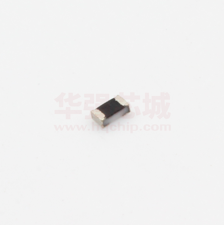
WR04X1583FTL

WR04X1583FTL

  • 厂商:

    WALSIN(华新科)

  • 封装:

    0402

  • 描述:

    贴片电阻 0402 158KΩ ±1% 1/16W ±100ppm/℃

  • 详情介绍
  • 数据手册
  • 价格&库存
WR04X1583FTL 数据手册
Approval sheet WR12, WR08, WR06, WR04 ±1%, ±5% Thick Film General Purpose Chip Resistors Size 1206, 0805, 0603, 0402 *Contents in this sheet are subject to change without prior notice. Page 1 of 10 ASC_WR_V23 APR.- 2015 Approval sheet FEATURE 1. High reliability and stability 2. Reduced size of final equipment 3. Lower assembly costs 4. Higher component and equipment reliability 5. RoHS compliant and Lead free products APPLICATION • Consumer electrical equipment • EDP, Computer application • Telecom application DESCRIPTION The resistors are constructed in a high grade ceramic body (aluminum oxide). Internal metal electrodes are added at each end and connected by a resistive paste that is applied to the top surface of the substrate. The composition of the paste is adjusted to give the approximate resistance required and the value is trimmed to within tolerance by laser cutting of this resistive layer. The resistive layer is covered with a protective coat. Finally, the two external end terminations are added. For ease of soldering the outer layer of these end terminations is a Tin (lead free) alloy. Fig 1. Construction of Chip-R Page 2 of 10 ASC_WR_V23 APR.- 2015 Approval sheet QUICK REFERENCE DATA Item General Specification Series No. WR12 WR08 WR06 WR04 Size code 1206(3216) 0805(2012) 0603(1608) 0402(1005) Resistance Range 1Ω~10MΩ (±5% tolerance), Jumper 1Ω~10MΩ (±1% tolerance), Resistance Tolerance ±1% ±5% ±1% ±5% ±1% ±5% ±1% ±5% E96/E24 E24 E96/E24 E24 E96/E24 E24 E96/E24 E24 TCR (ppm/°C) 10MΩ ≥R>10Ω ≤ ± 100 R≤10Ω -200~+400 Max. dissipation @ Tamb=70°C 1/4 W 1/8 W 1/10 W 1/16 W Max. Operation Voltage (DC or RMS) 200V 150V 75V 50V Max. Overload Voltage (DC or RMS) 400V 300V 150V 100V Climatic category 55/155/56 Note : 1. This is the maximum voltage that may be continuously supplied to the resistor element, see “IEC publication 60115-8” 2. Max. Operation Voltage : So called RCWV (Rated Continuous Working Voltage) is determined by RCWV = Rated Power × Resistance Value or Max. RCWV listed above, whichever is lower. 3. The resistance of Jumper is defined 1MΩ B Jumper =000_ D : 7'' reel 20Kpcs only for 0402 (“_” means a blank) ±1%, E24+E96: 3 significant digits followed by no. of zeros 102Ω =1020 37.4KΩ =3742 : 7” Reeled taping : Bulk A : 7" reel 15Kpcs only for 0402 WR12, WR08, WR06: 1. Reeled tape packaging : 8mm width paper taping 5000pcs per 7” reel, 10kpcs per 10” reel, 20kpcs per 13” reel. 2. Bulk packaging Page 6 of 10 : 5000pcs per poly-bag ASC_WR_V23 APR.- 2015 Approval sheet WR04: 1. reel. 2. Reeled tape packaging : 8mm width paper taping 10,000pcs per 7” reel, 20,000pcs per 10” reel. 70,000pcs per 13” Bulk packaging Page 7 of 10 : 10,000pcs per poly-bag ASC_WR_V23 APR.- 2015 Approval sheet TEST AND REQUIREMENTS Essentially all tests are carried out according to the schedule of IEC publication 115-8, category LCT/UCT/56(rated temperature range : Lower Category Temperature, Upper Category Temperature; damp heat, long term, 56 days). The testing also meets the requirements specified by EIA, EIAJ and JIS. The tests are carried out in accordance with IEC publication 68, "Recommended basic climatic and mechanical robustness testing procedure for electronic components" and under standard atmospheric conditions according to IEC 60068-1, subclause 5.3. Unless otherwise specified, the following value supplied : Temperature: 15°C to 35°C. Relative humidity: 45% to 75%. Air pressure: 86kPa to 106 kPa (860 mbar to 1060 mbar). All soldering tests are performed with midly activated flux. TEST REQUIREMENT PROCEDURE / TEST METHOD 0Ω Ω Resistor Electrical - DC resistance values measurement Within the specified tolerance Characteristics - Temperature Coefficient of Resistance (T.C.R) Refer to “QUICK REFERENCE Natural resistance change per change in degree centigrade. DATA” R2 − R1 × 106 R1 (t2 − t1 ) JISC5201-1: 1998 Clause 4.8 (ppm/°C) t1 : 20°C+5°C-1°C; t 2
WR04X1583FTL
1. 物料型号: - WR12: 尺寸代码1206(3216) - WR08: 尺寸代码0805(2012) - WR06: 尺寸代码0603(1608) - WR04: 尺寸代码0402(1005)

2. 器件简介: - 这些是薄膜通用芯片电阻器,具有高可靠性和稳定性,减小了最终设备的尺寸,降低了组装成本,提高了组件和设备的可靠性,并且符合RoHS标准,无铅产品。

3. 引脚分配: - 文档中没有明确提到引脚分配,但通常这类表面贴装电阻器有两端的外部端接点用于焊接。

4. 参数特性: - 电阻范围:1~10M,有5%和1%的容差。 - 温度系数(TCR):对于10MΩ以上的电阻,TCR ≤±100ppm/°C;对于小于或等于10Ω的电阻,TCR在-200~+400ppm/°C之间。 - 最大耗散功率:WR12为1/4W,WR08为1/8W,WR06为1/10W,WR04为1/16W。 - 最大工作电压和过载电压根据不同型号有所不同,具体数值请参考文档中的“QUICK REFERENCE DATA”部分。

5. 功能详解: - 电阻器由高级陶瓷体(氧化铝)构成,两端添加内部金属电极,并通过涂在基板顶面上的电阻浆料连接。浆料的组成被调整以提供所需的大致电阻值,并通过激光切割电阻层来微调至规定的容差内。

6. 应用信息: - 适用于消费电子设备、电子数据处理、计算机应用、电信应用等领域。

7. 封装信息: - 提供了详细的尺寸信息,包括长度(L)、宽度(W)、厚度(T)、基板厚度(Tb)和端接点厚度(Tt)。

8. 标记: - 根据电阻的尺寸和容差,电阻上有3位或4位数字的标记,用以表示标称电阻值。

9. 功能描述: - 标准电阻值采用E24系列(±5%容差)和E96系列(±1%容差)。

10. 焊接条件: - 芯片电阻器可以完全浸入260°C的焊料浴中10秒,适用于双面混合PCB的焊接。

11. 目录编号: - 电阻器有目录编号,包括尺寸代码、类型代码、电阻代码、容差、包装代码和端接点代码。

12. 测试和要求: - 所有测试均按照IEC出版物115-8的LCT/UCT/56类别进行,测试也满足EIA、EIAJ和JIS指定的要求。
WR04X1583FTL 价格&库存

很抱歉,暂时无法提供与“WR04X1583FTL”相匹配的价格&库存,您可以联系我们找货

免费人工找货
WR04X1583FTL
    •  国内价格 香港价格
    • 10000+0.0064910000+0.00078
    • 50000+0.0064750000+0.00078
    • 200000+0.00647200000+0.00078
    • 500000+0.00647500000+0.00078
    • 1250000+0.005571250000+0.00067

    库存:100000

    WR04X1583FTL
    •  国内价格
    • 100+0.00322
    • 500+0.00302
    • 1000+0.00272
    • 5000+0.00232
    • 10000+0.00208

    库存:9790

    WR04X1583FTL
      •  国内价格
      • 1+0.00376
      • 100+0.00327
      • 1000+0.00297
      • 1670+0.00283
      • 5000+0.00201
      • 10000+0.00171

      库存:1600

      WR04X1583FTL
        •  国内价格
        • 100+0.00400
        • 1000+0.00314
        • 3000+0.00270
        • 10000+0.00249
        • 50000+0.00227

        库存:3823